Related Research Articles

Signals intelligence (SIGINT) is intelligence-gathering by interception of signals, whether communications between people or from electronic signals not directly used in communication. Signals intelligence is a subset of intelligence collection management. As classified and sensitive information is usually encrypted, signals intelligence in turn involves the use of cryptanalysis to decipher the messages. Traffic analysis—the study of who is signaling whom and in what quantity—is also used to integrate information again.

Very high frequency (VHF) is the ITU designation for the range of radio frequency electromagnetic waves from 30 to 300 megahertz (MHz), with corresponding wavelengths of ten meters to one meter. Frequencies immediately below VHF are denoted high frequency (HF), and the next higher frequencies are known as ultra high frequency (UHF).

Radio navigation or radionavigation is the application of radio frequencies to determine a position of an object on the Earth, either the vessel or an obstruction. Like radiolocation, it is a type of radiodetermination.

Medium frequency (MF) is the ITU designation for radio frequencies (RF) in the range of 300 kilohertz (kHz) to 3 megahertz (MHz). Part of this band is the medium wave (MW) AM broadcast band. The MF band is also known as the hectometer band as the wavelengths range from ten to one hectometer. Frequencies immediately below MF are denoted low frequency (LF), while the first band of higher frequencies is known as high frequency (HF). MF is mostly used for AM radio broadcasting, navigational radio beacons, maritime ship-to-shore communication, and transoceanic air traffic control.
In radio engineering, an antenna or aerial is the interface between radio waves propagating through space and electric currents moving in metal conductors, used with a transmitter or receiver. In transmission, a radio transmitter supplies an electric current to the antenna's terminals, and the antenna radiates the energy from the current as electromagnetic waves. In reception, an antenna intercepts some of the power of a radio wave in order to produce an electric current at its terminals, that is applied to a receiver to be amplified. Antennas are essential components of all radio equipment.

Effective radiated power (ERP), synonymous with equivalent radiated power, is an IEEE standardized definition of directional radio frequency (RF) power, such as that emitted by a radio transmitter. It is the total power in watts that would have to be radiated by a half-wave dipole antenna to give the same radiation intensity as the actual source antenna at a distant receiver located in the direction of the antenna's strongest beam. ERP measures the combination of the power emitted by the transmitter and the ability of the antenna to direct that power in a given direction. It is equal to the input power to the antenna multiplied by the gain of the antenna. It is used in electronics and telecommunications, particularly in broadcasting to quantify the apparent power of a broadcasting station experienced by listeners in its reception area.

In radio communication, skywave or skip refers to the propagation of radio waves reflected or refracted back toward Earth from the ionosphere, an electrically charged layer of the upper atmosphere. Since it is not limited by the curvature of the Earth, skywave propagation can be used to communicate beyond the horizon, at intercontinental distances. It is mostly used in the shortwave frequency bands.

Very high frequency omni-directional range (VOR) is a type of short-range radio navigation system for aircraft, enabling aircraft with a receiving unit to determine its position and stay on course by receiving radio signals transmitted by a network of fixed ground radio beacons. It uses frequencies in the very high frequency (VHF) band from 108.00 to 117.95 MHz. Developed in the United States beginning in 1937 and deployed by 1946, VOR was the standard air navigational system in the world, used by both commercial and general aviation, but as of 2015, commercial aviation relies almost exclusively on satellite navigation systems such as GPS. As such, VOR stations are being gradually decommissioned. In the year 2000 there were about 3,000 VOR stations operating around the world, including 1,033 in the US, but by 2013 the number in the US had reduced to 967. The United States is decommissioning approximately half of its VOR stations and other legacy navigation aids as part of a move to performance-based navigation, while still retaining a "Minimum Operational Network" of VOR stations as a backup to GPS. In 2015 the UK planned to reduce the number of stations from 44 to 19 by 2020.
Telefunken was a German radio and television apparatus company, founded in Berlin in 1903, as a joint venture of Siemens & Halske and the Allgemeine Elektricitäts-Gesellschaft (AEG).

Direction finding (DF), or radio direction finding (RDF), is – in accordance with International Telecommunication Union (ITU) – defined as radio location that uses the reception of radio waves to determine the direction in which a radio station or an object is located. This can refer to radio or other forms of wireless communication, including radar signals detection and monitoring (ELINT/ESM). By combining the direction information from two or more suitably spaced receivers, the source of a transmission may be located via triangulation. Radio direction finding is used in the navigation of ships and aircraft, to locate emergency transmitters for search and rescue, for tracking wildlife, and to locate illegal or interfering transmitters. RDF was important in combating German threats during both the World War II Battle of Britain and the long running Battle of the Atlantic. In the former, the Air Ministry also used RDF to locate its own fighter groups and vector them to detected German raids.

A television antenna is an antenna specifically designed for use with a television receiver (TV) to receive over-the-air broadcast television signals from a television station. Television reception is dependent upon the antenna as well as the transmitter. Terrestrial television is broadcast on frequencies from about 47 to 250 MHz in the very high frequency (VHF) band, and 470 to 960 MHz in the ultra high frequency (UHF) band in different countries. Television antennas are manufactured in two different types: "indoor" antennas, to be located on top of or next to the television set, and "outdoor" antennas, mounted on a mast on top of the owner's house. They can also be mounted in a loft or attic, where the dry conditions and increased elevation are advantageous for reception and antenna longevity. Outdoor antennas are more expensive and difficult to install, but are necessary for adequate reception in fringe areas far from television stations. The most common types of indoor antennas are the dipole and loop antennas, and for outdoor antennas the yagi, log periodic, and for UHF channels the multi-bay reflective array antenna.

In radio communication, a ground dipole, also referred to as an earth dipole antenna, transmission line antenna, and in technical literature as a horizontal electric dipole (HED), is a huge, specialized type of radio antenna that radiates extremely low frequency (ELF) electromagnetic waves. It is the only type of transmitting antenna that can radiate practical amounts of power in the frequency range of 3 Hz to 3 kHz, commonly called ELF waves. A ground dipole consists of two ground electrodes buried in the earth, separated by tens to hundreds of kilometers, linked by overhead transmission lines to a power plant transmitter located between them. Alternating current electricity flows in a giant loop between the electrodes through the ground, radiating ELF waves, so the ground is part of the antenna. To be most effective, ground dipoles must be located over certain types of underground rock formations. The idea was proposed by U.S. Dept. of Defense physicist Nicholas Christofilos in 1959.

Nauen Transmitter Station in Nauen, Havelland district, Brandenburg, Germany, is the oldest continuously operating radio transmitting installation in the world. Germany's first high power radio transmitter, it was founded on 1 April 1906 by Telefunken corporation and operated as a longwave radiotelegraphy station through World War II, and during World War I became Germany's main link with the outside world when its submarine communications cables were cut. Upgraded with shortwave transmitters in the 1920s it was Germany's most advanced long range radio station, continually upgraded with the latest equipment and serving as an experimental station for Telefunken to test new technology. At the end of World War II, invading Russian troops dismantled and removed the transmitting equipment. During the Cold War it served as the GDR's international shortwave station Radio Berlin International (RBI), and was the East Bloc's second most powerful radio station, disseminating Communist propaganda to other countries. Since German Reunification in 1991 it has been operated by Deutsche Telekom, Germany's state telecommunication service. The original 1920 transmitter building designed by architect Herman Muthesius is still used; it is the only remaining building designed by that architect.

Radio is the technology of signaling and communicating using radio waves. Radio waves are electromagnetic waves of frequency between 30 hertz (Hz) and 300 gigahertz (GHz). They are generated by an electronic device called a transmitter connected to an antenna which radiates the waves, and received by another antenna connected to a radio receiver. Radio is very widely used in modern technology, in radio communication, radar, radio navigation, remote control, remote sensing, and other applications.

An antenna array is a set of multiple connected antennas which work together as a single antenna, to transmit or receive radio waves. The individual antennas are usually connected to a single receiver or transmitter by feedlines that feed the power to the elements in a specific phase relationship. The radio waves radiated by each individual antenna combine and superpose, adding together to enhance the power radiated in desired directions, and cancelling to reduce the power radiated in other directions. Similarly, when used for receiving, the separate radio frequency currents from the individual antennas combine in the receiver with the correct phase relationship to enhance signals received from the desired directions and cancel signals from undesired directions. More sophisticated array antennas may have multiple transmitter or receiver modules, each connected to a separate antenna element or group of elements.
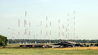
Curtain arrays are a class of large multielement directional radio transmitting wire antennas, used in the shortwave radio bands. They are a type of reflective array antenna, consisting of multiple wire dipole antennas, suspended in a vertical plane, often in front of a "curtain" reflector made of a flat vertical screen of many long parallel wires. These are suspended by support wires strung between pairs of tall steel towers, up to 90 m high. They are used for long-distance skywave transmission; they transmit a beam of radio waves at a shallow angle into the sky just above the horizon, which is reflected by the ionosphere back to Earth beyond the horizon. Curtain antennas are mostly used by international short wave radio stations to broadcast to large areas at transcontinental distances.
The Orfordness Rotating Wireless Beacon, known simply as the Orfordness Beacon or sometimes the Black Beacon, was an early radio navigation system introduced by the United Kingdom in July 1929. It allowed the angle to the station to be measured from any aircraft or ship with a conventional radio receiver, and was accurate to about a degree. A second station operating on the same principle was set up to provide wider area coverage and allow two-bearing fixes between Orford Ness and Farnborough Airport. The system was similar to the earlier German Telefunken Kompass Sender and the later Sonne system.
Sonne was a radio navigation system developed in Germany during World War II. It was developed from an earlier experimental system known as Elektra, and therefore the system is also known as Elektra-sonnen. When the British learned of the system they started using it as well, under the name Consol, meaning "by the sun".

A Bellini–Tosi direction finder is a type of radio direction finder (RDF), which determines the direction to, or bearing of, a radio transmitter. Earlier RDF systems used very large rotating loop antennae, which the B–T system replaced with two fixed antennae and a small rotating loop, known as a radiogoniometer. This made RDF much more practical, especially on large vehicles like ships or when using very long wavelengths that demand large antennae.
In radio systems, many different antenna types are used with specialized properties for particular applications. Antennas can be classified in various ways. The list below groups together antennas under common operating principles, following the way antennas are classified in many engineering textbooks.
References
- Annis Salsbury, "Safeguarding Vessels by Radio", Popular Science, January-June 1916, pp. 451-453
- Arthur Bauer, "Some historical and technical aspects of radio navigation, in Germany, over the period 1907 to 1945", 26 December 2004
- "How the Zeppelin Raiders Are Guided by Radio Signals", Popular Science, April 1918, pp. 62-634