AN/MPQ-4

Last updated
AN/MPQ-4
AN MPQ-4A.jpg
AN/MPQ-4
Country of originUS
ManufacturerGeneral Electric
Introduced1958 (1958)
TypeCounterbattery
Frequency16 GHz (Ku band)
PRF 7000 pps
Beamwidth 14.25 mils (0.362 mm)
Pulsewidth0.25 µs
Range225 to 15,000 m (738–49,213 ft)
Azimuth 25°, but rotatable through 180°
Elevation−6° to +12°
Precision50 m at 10,000 m
Power50 kW
Other NamesJAN/MPQ-N1 Type 72

The Radar Set AN/MPQ-4 was a US Army counter-battery radar primarily used to find the location of enemy mortars and larger artillery in a secondary role. Built by General Electric, it first entered service in 1958, replacing the earlier and much simpler AN/MPQ-10. The MPQ-4 could determine the location of an enemy mortar in as little as 20 seconds by observing a single round, whereas the MPQ-10 required several rounds to be launched and could take 4 to 5 minutes to take a "fix". The MPQ-4 remained one of the primary US counter-battery systems through the late 1970s until it was replaced by passive electronically scanned array radars like the AN/TPQ-36.

Contents

History

During World War II, operators or the newly introduced SCR-584 radar noticed they sometimes could see artillery shells in flight. With considerable effort, they could follow these rounds and then manually estimate the radial trajectory. By looking along that path, they could see the rounds being launched and then forward that information to friendly artillery units. [1]

The US Army's first counter-battery radar was the AN/MPQ-10. This was essentially a smaller version of the SCR-584 mounted on a Bofors 40 mm gun carriage. Introduced in 1951, the system remained manually operated, although with a few modifications to make the operation somewhat similar. Tracking down an enemy mortar generally took on the order of 4 to 5 minutes, and required a number of rounds to be fired. [2] The AN/KPQ-1 attempted to improve on this by using five radar antennas aimed at slightly different angles horizontally, spreading the beam out so it covered a larger area of the horizon. [3]

A better solution to the problem of seeing the first round had been developed by John Stuart Foster while working at the MIT Radiation Laboratory as part of a technical exchange from the Canadian National Research Council. The Foster scanner was a mechanical system that rapidly scanned moved a radar signal back and forth along a selected axis. For the counter-battery role, the beam was scanned horizontally, so any round launched across a wide angle in front of the radar would be seen as it passed through the fan-shaped beam. [4]

The AN/MPQ-4 was the first operational counter-battery radar to use the Foster scanner. It entered service in 1958, sending the MPQ-10 to secondary roles, mostly for tracking outgoing rounds from friendly artillery for adjusting fire. [5] The MPQ-4 was widely used in the Vietnam War, where it was often emplaced on short wooden platforms to provide an improved view of the horizon. [6] [7]

Digital electronics and passive scanning of the signal made the MPQ-4 obsolete. Two replacements were developed, the AN/TPQ-36 and the larger AN/TPQ-37 Firefinder systems, with the TPQ-36 undergoing extensive qualification testing between 1975 and 1979 and entering deployed service in 1982. [8]

Description

The primary signal in the MPQ-4 was supplied by a Ku band cavity magnetron. [9] The signal was sent into a Foster scanner that produced an output 17.8 mils wide and 14.25 mils high (1 by 0.8 degrees) and scanned it back and forth horizontally 17 times a second. The resulting pattern was a fan shape, narrow vertically and 445 mils (~25 degrees) wide horizontally. A splitter, the "beam separation plate", split the original input beam into two slightly separated signals. The result was two stacked fans positioned 36 mils (~2 degrees) apart vertically. [10]

When a round was fired it would penetrate the two beams in turn. Returns from both were sent to the same B-scope display, causing two blips to appear. When the first appeared, the operator would turn two hand wheels to move a horizontal and vertical lines on the display, the strobes, so they lay on top of the blip. They then waited for the round to appear in the upper beam, causing another blip to appear. This time they used a second set of wheels to move the strobes to the new location. The entire process takes as little as 20 seconds. [11] [2]

The handwheels were connected to an analog computer that continually output the calculated coordinates of the launcher. The calculation was quite simple, using a straight line interpolation between the two points to determine the location. [12] This was expressed as range and azimuth, and by entering the location of the radar prior to measurement, the relative position (easting and northing) in meters. [13] If the values were unlikely to be accurate, a red lamp lit on the panel. [2]

To help accurately position the strobes, a range-gate system could be used to magnify the display. This had the effect of moving the blips apart vertically, making the difference between them more pronounced. [14] The system was also generally more accurate if it was pointed at a low angle, so the difference between the actual parabolic path and the straight line extrapolated by the computer was minimized. [12]

Accuracy could be further improved by turning another wheel to indicate the time between the appearance of the two blips. A stopwatch-like timer was positioned to the right of the main display to make this easy. However, the main purpose of this timer was to allow the system to calculate the vertical velocity of the round, and from that, the expected peak of the trajectory, which was then used to calculate the impact point. [10]

The system could also be used with some capability against artillery that fired at a lower angle, like a howitzer. Since a shell from such a weapon might never climb high enough to cross both beams, the system had a second mode that used a single wider beam instead. In this "single beam" mode the shell would appear on the display and then disappear again after some time, resulting in a long streak instead of a small blip. The calculation was carried out as normal by positioning the strobes at either end of the streak. [15]

The system had a maximum range of 15,000 metres (9.3 mi) [16] and could be used effectively at that range. [17] Accuracy was about 15 metres (49 ft) in range and 1.5 mils in azimuth, but the resolution of the display limited that to about 50 metres (160 ft). [18]

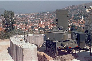
The system was packed onto a 1½ ton trailer, with the radar scanner roughly centered and the operator's console on a mount at the back. The system could be operated directly from the back of the trailer, or the console could be removed and connected back to the radar using a 150 foot (46 m) cable. Power was supplied by a 400 Hz generator. Total weight was about 6,100 pounds (2,800 kg). [17] Setup time was typically 15 to 30 minutes. [9]

See also

Related Research Articles

<span class="mw-page-title-main">Counter-battery radar</span> Radar that locates artillery pieces by tracking their projectiles

A counter-battery radar or weapon tracking radar is a radar system that detects artillery projectiles fired by one or more guns, howitzers, mortars or rocket launchers and, from their trajectories, locates the position on the ground of the weapon that fired it. Such radars are a subclass of the wider class of target acquisition radars.

<span class="mw-page-title-main">AN/MPQ-64 Sentinel</span> American short-range air defense radar

The AN/MPQ-64 Sentinel is an X-band electronically steered pulse-Doppler 3D radar system used to alert and cue Short Range Air Defense (SHORAD) weapons to the locations of hostile targets approaching their front line forces. It is currently produced by Raytheon Missiles & Defense.
<span class="mw-page-title-main">AN/TPQ-36 Firefinder radar</span> American mobile radar system

Hughes AN/TPQ-36 Firefinder weapon locating system is a mobile radar system developed in the mid-late 1970s by Hughes Aircraft Company and manufactured by Northrop Grumman and ThalesRaytheonSystems, achieving initial operational capability in May 1982. The system is a "weapon-locating radar", designed to detect and track incoming mortar, artillery and rocket fire to determine the point of origin for counter-battery fire. It is currently in service at battalion and higher levels in the United States Army, United States Marine Corps, Australian Army, Portuguese Army, Turkish Army, and the Armed Forces of Ukraine.

<span class="mw-page-title-main">Passive electronically scanned array</span> Type of antenna

A passive electronically scanned array (PESA), also known as passive phased array, is an antenna in which the beam of radio waves can be electronically steered to point in different directions, in which all the antenna elements are connected to a single transmitter and/or receiver. The largest use of phased arrays is in radars. Most phased array radars in the world are PESA. The civilian microwave landing system uses PESA transmit-only arrays.

<span class="mw-page-title-main">AN/TPQ-37 Firefinder radar</span> US mobile counter-battery radar system

Hughes AN/TPQ-37 Firefinder Weapon Locating System is a mobile radar system developed in the late 1970s by Hughes Aircraft Company, achieving Initial Operational Capability in 1980 and full deployment in 1984. Currently manufactured by ThalesRaytheonSystems, the system is a long-range version of "weapon-locating radar", designed to detect and track incoming artillery and rocket fire to determine the point of origin for counter-battery fire. It is currently in service at brigade and higher levels in the United States Army and by other countries. The radar is trailer-mounted and towed by a 2+13-short-ton (2,100 kg) truck. A typical AN/TPQ-37 system consists of the Antenna-Transceiver Group, Command Shelter and 60 kW Generator.

<span class="mw-page-title-main">SLC-2 Radar</span>

The SLC-2 Radar is a Chinese active electronically scanned array counter-battery radar designed to locate hostile artillery, rocket and ground-to-ground missile launchers immediately after firing, and to support friendly artillery by guiding counter-battery fire.

The Type 704 is a counter-battery radar designed to accurately locate the hostile artillery, rocket and ground-to-ground missile launcher immediately after the firing of enemy, and support friendly artillery by providing guidance of counter fire. Built by NORINCO, it was first displayed publicly in 1988's ASIADEX defence show.

<span class="mw-page-title-main">ARTHUR</span> Counter-battery radar system

ARTHUR is a counter-battery radar system originally developed jointly for and in close co-operation with the Norwegian and Swedish armed forces by Ericsson Microwave Systems in both Sweden and Norway. It is also used by the British Army, under the names mobile artillery monitoring battlefield radar or mobile artillery monitoring battlefield asset (MAMBA).

<span class="mw-page-title-main">Radar display</span> Electronic device

A radar display is an electronic device that presents radar data to the operator. The radar system transmits pulses or continuous waves of electromagnetic radiation, a small portion of which backscatter off targets and return to the radar system. The receiver converts all received electromagnetic radiation into a continuous electronic analog signal of varying voltage that can be converted then to a screen display.
<span class="mw-page-title-main">Counter rocket, artillery, and mortar</span> Military air defense system

Counter rocket, artillery, and mortar, abbreviated C-RAM or counter-RAM, is a set of systems used to detect and/or destroy incoming rockets, artillery, and mortar rounds in the air before they hit their ground targets, or simply provide early warning.

<span class="mw-page-title-main">Swathi Weapon Locating Radar</span> Counter-battery radar

The Swathi weapon locating radar is a mobile artillery-locating, phased array radar developed by India. This counter-battery radar is designed to detect and track incoming artillery and rocket fire to determine the point of origin for counter-battery fire.

The AN/MPQ-49 Forward Area Alerting Radar (FAAR) is a lightweight early warning radar system consisting of the AN/TPQ-43 radar, AN/TPX-50 Mark XII IFF receiver, a 5 kW generator set, and a Gama Goat providing mobility.

<span class="mw-page-title-main">AN/TPQ-53 Quick Reaction Capability Radar</span> Ground radar system

AN/TPQ-53 Quick Reaction Capability Radar is a mobile active electronically scanned array counter-battery radar system manufactured by Lockheed Martin. The radar is specifically designed to locate the firing positions of both rocket and mortar launchers.

Green Archer, also called Radar, Field Artillery, No 8 was a widely used British mortar locating radar operating in the X band using a Foster scanner. Developed by EMI after an experimental model by the Royal Radar Establishment, it was in British service from 1962 until 1975 with the Royal Artillery. A self-propelled version was designated FV436 or Radar, FA, No 8 Mk 2. It was replaced by Cymbeline starting in 1975.

<span class="mw-page-title-main">Cymbeline (radar)</span>

Radar, Field Artillery, No 15, better known as Cymbeline, was a widely used British mortar locating radar operating in the I band using a Foster scanner. Developed by Thorn-EMI and built at their now-defunct site at Hayes in Middlesex, it was in British service from 1975 until about 2003 with the Royal Artillery.

<span class="mw-page-title-main">Foster scanner</span> Type of radar system

The Foster scanner, or Variable Path scanner, is a type of radar system that produces a narrow beam that rapidly scans an area in front of it. Foster scanners were widely used in post-World War II radar systems used for artillery and mortar spotting. Modern radars in this role normally use electronic scanning in place of a Foster scanner for this purpose.

A time base generator is a special type of function generator, an electronic circuit that generates a varying voltage to produce a particular waveform. Time base generators produce very high frequency sawtooth waves specifically designed to deflect the beam of a cathode ray tube (CRT) smoothly across the face of the tube and then return it to its starting position.

<span class="mw-page-title-main">AMES Type 82</span> Cold War-era British medium-range 3D radar

The AMES Type 82, also widely known by its rainbow codename Orange Yeoman, was an S-band 3D radar built by Marconi and used by the Royal Air Force (RAF), initially for tactical control and later for air traffic control (ATC).

<span class="mw-page-title-main">Red Steer</span> Tail warning radar

Red Steer, also known as ARI 5919 and ARI 5952 depending on the version, was a tail warning radar used on the British V bomber force. Built by EKCO, it was developed from the experimental AI.20 radar for the English Electric Lightning. The Lightning required its radar to be remotely installed in the nose of the aircraft, and this made the set equally suitable for remote mounting in the tail of the bombers.

References

Citations

  1. Orman, Leonard (1947). "Counter-Mortar Radar". The Field Artillery Journal. United States Field Artillery Association: 88.
  2. 1 2 3 Marschhausen 1958, p. 3.
  3. Ayliffe, Keith (2009). "AN/KPQ-1 Radar" (PDF). p. 41.
  4. Foster, John (1945). Linear Electrical Scanner (Technical report). MIT Radiation Laboratory.
  5. Marschhausen 1958, pp. 4–5.
  6. Ott, David (1975). Field Artillery, 1954-1973. US Army. p. 71.
  7. Moïse, Edwin (2005). The A to Z of the Vietnam War. Scarecrow Press. p. 331. ISBN   9781461719038.
  8. "AN/TPQ-36, AN/TPQ-37 Tests Termed 'Spectacular'". Army R, D & A Bulletin. Army Materiel Command: 12. November–December 1975.
  9. 1 2 Manual 1977, p. 1-3.
  10. 1 2 Manual 1977, p. 1-15.
  11. Manual 1977, pp. 3-24–3-26.
  12. 1 2 Manual 1977, p. 3-19.
  13. Manual 1977, pp. 1–15, 3–26.
  14. Manual 1977, p. 3-25.
  15. Manual 1977, pp. 1–15, 3–20.
  16. Manual 1977, p. 2-1.
  17. 1 2 Marschhausen 1958, p. 4.
  18. Manual 1977, p. 1-2.

Bibliography