Rebecca/Eureka transponding radar

Last updated
Sgt. William T. Alexander, flight engineer, with B-24D#42-63980 of the 858th BS, 801st/492nd BG "Carpetbaggers" in 1944, showing Yagi antenna for Rebecca transceiver Rebecca-antenna-B-24D-Playmate.jpg
Sgt. William T. Alexander, flight engineer, with B-24D#42-63980 of the 858th BS, 801st/492nd BG "Carpetbaggers" in 1944, showing Yagi antenna for Rebecca transceiver

The Rebecca/Eureka transponding radar was a short-range radio navigation system used for the dropping of airborne forces and their supplies. It consisted of two parts, the Rebecca airborne transceiver and antenna system, and the Eureka ground-based transponder. Rebecca calculated the range to the Eureka based on the timing of the return signals, and its relative position using a highly directional antenna. The 'Rebecca' name comes from the phrase "Recognition of beacons". The 'Eureka' name comes from the Greek word meaning "I have found it!".

Contents

The system was developed in the UK at the Telecommunications Research Establishment by Robert Hanbury Brown and John William Sutton Pringle. Rebecca was essentially an ASV radar fit to a new broadcaster unit, while the Eureka system was all-new. Initial production began in 1943, and the system was used for dropping supplies to resistance fighters in occupied Europe, after delivery of the portable Eureka unit. The US Army Air Force started production in the US as well, and both examples could be used interchangeably. Over time, the Rebecca/Eureka found a number of other uses, including blind-bombing, airfield approach, and as a blind-landing aid in the BABS (Beam Approach Beacon Signal) form.

As many of the war-era systems used similar display units, the Lucero system was introduced to send the proper signals to interrogate any of these systems, allowing a single display unit of any type to be used for H2S, ASV, AI, Rebecca and BABS.

History

Lucky accident

Mk. IV-equipped Bristol Beaufighter Royal Air Force Radar, 1939-1945 CH15214.jpg
Mk. IV-equipped Bristol Beaufighter

Rebecca/Eureka owes its existence largely to the efforts of Robert Hanbury Brown, an astronomer and physicist who worked with the Air Ministry's AMES group on the development of radar. During 1940, Brown had led development of a new version of the AI Mk. IV radar that included a pilot's indicator, better known today as a C-scope. This display directly represented the relative position between the fighter and its target, as if the pilot were looking through a gunsight. It was hoped that this would greatly ease the problems that the radar operators had trying to relay instructions from their instruments to the pilot, especially at closer range. [1]

Prototype sets became available in late 1940, with the first production examples arriving in January 1941. During a test flight in February, the aircraft was flying at 20,000 feet (6.1 km) when Hanbury Brown's oxygen supply failed and he passed out. The test pilot, Peter Chamberlain, realized what had happened and quickly landed the plane. Brown awoke in an ambulance. [2] This accident, along with the many previous flights at high altitude, aggravated an ear injury he had received at RAF Martlesham Heath in 1939, and during the spring he was hospitalized for a mastoidectomy operation in Brighton. The operation was successful, but a post-operation infection caused him to go deaf in both ears and several follow-up visits were required. [2]

By the time he returned to the AMES research center, now in Worth Matravers and renamed the Telecommunications Research Establishment (TRE), major research on the early AI sets had ended in favour of new systems working at microwave frequencies using the recently invented cavity magnetron. Brown had missed most of the development of this system, and he was no longer allowed to fly at high altitudes, so his work on AI ended. He was instead placed in a new group led by John Pringle, a zoologist from Cambridge University, and the two began to study new applications for radar technologies. [3]

Beacons for Army Co-operation

In June 1941, Brown visited the Army headquarters at Old Sarum Airfield to see if the RAF Army Co-operation Command's School of Army Co-operation might put radar to good use. The Army Co-operation squadrons carried out a variety of missions including artillery spotting, general reconnaissance, and ground attack. He found the group was only mildly interested in radar, thinking it might make a useful device for warning of the approach of enemy fighters, but were perfectly happy using flags and smoke signals for navigation and communications. [3] Brown then visited a military exercise involving ground attacks in close coordination with the Army, and was convinced that radar systems could be used to improve these results. However, he also came to realize that almost all such missions would be carried out by aircraft of other forces, notably the RAF, so any system they proposed would have to be mounted in those aircraft. [4]

Pringle then arranged for Brown and himself to meet with the Commander in Chief (C-in-C) for Army Co-operation, Sir Arthur Barratt. In a long conversation, the two outlined the possibilities of radar for bombing, navigation and return-to-base roles, all of which proved to be interesting to Barratt. Barratt then stated that any system they did adopt would have to fit in single seat aircraft like the Tomahawk, which eliminated most of these possibilities. Both Pringle and Brown then focused on the use of a transponder system combined with existing radars to allow accurate bombing or delivery of supplies or troops by parachute, a role that would almost always be carried out by twin-engine aircraft or larger. If this broadcast on the 200 MHz frequency then being used by many British radars, any aircraft with AI or Air-to-Surface Vessel radar could pick it up. [4]

To illustrate the concept, Brown gave them a small transponder and told them to hide it anywhere within 15 miles (24 km) of Army Co-operation headquarters in Bracknell. One of the TRE aircraft from RAF Christchurch would attempt to find it and fire a smoke signal within 100 yards (91 m) of its location. The test was carried out on 28 July 1941, and while they waited for their aircraft to arrive, another aircraft approached the hiding spot and flew around several times before flying off again. The Army suspected that they had sent this aircraft to spy out the location. Just as Brown managed to convince them they were not spies, their own aircraft, a Bristol Blenheim, arrived and fired a smoke signal only 50 yards from the transponder. To be sure, the Army was told to hide it again in another location, this time choosing to place under a tree on the lawn of their headquarters. Their Blenheim once again easily found it. It was later learned that the first aircraft was from the Fighter Interception Unit who saw the odd blip on their radar and decided to investigate. [5]

In spite of the successful demonstrations, and enthusiastic support from Barratt and others, no orders for a transponder system were immediately forthcoming. A visit to the airborne headquarters at RAF Ringway would ultimately result in orders for both the UK and US, but those would be some time in the making. [5]

SOE

A more immediate outcome of the visit to Ringway was an invitation for Brown to meet a secret group known as the Special Operations Executive (SOE) at Whitehall. Brown arrived to find this was not actually their office, and had to prove his identity before being told the real address was quite a distance away. When he finally arrived at Baker Street he was not impressed. [6]

SOE then explained the problem they were having dropping supplies to partisans operating across Europe, as far away as Poland. Brown explained that their beacon could be seen as far as 50 miles (80 km) under good conditions, but that might drop to as short as 5 miles if it was under trees or otherwise blocked. SOE stated that they could be reasonably certain to place it on open ground. However, they also stated that they could only navigate to perhaps ten miles of the beacon, which would be only marginally satisfactory. Brown asked why they could not use the Gee navigation system to address this, and when they admitted they had no idea what this was, he had the satisfaction of saying he could not explain it to them because it was secret. [6]

Ultimately, Brown was taken to meet the C-in-C of the SOE and arranged a demonstration similar to the one given earlier for the Army. SOE was given the transponder and told to hide it anywhere within a large area, and their aircraft would not attempt to find it until a week later. On 11 February 1942 one of the TRE's Avro Ansons took off from RAF Hurn and picked it up at a range of 37 miles (60 km), approaching and dropping two containers within 200 yards. An order was placed immediately. [7]

Prototypes

One of the major problems with the original AI radars was that the transmissions spread out over the entire front hemisphere of the aircraft. Shorter wavelengths, like those used in AI, tended to scatter from the ground, sending a portion of the signal back towards the aircraft, the "ground reflection" or "ground return". For the simple reason that the ground is much larger than a target aircraft, the scattered signal overwhelmed any target return, and made it impossible to see any target further away than the aircraft's current altitude. For the supply mission, which was carried out at very low altitudes, this was clearly not going to work. [7]

As the SOE had their own aircraft, and there was no need to make the system work with an existing production radar design, the solution was relatively simple. Instead of the transponder replying on the same frequency, and thus being lost in the ground reflections, it would receive the signal from the radar and then re-broadcast it on a second frequency. In the aircraft, the receiver would be tuned not to the radar's broadcasts, but the transponder's. This way the ground reflection would simply be ignored, although at the cost of requiring the transponder to have two separate antenna systems. [7]

Powering the transponder was a more serious problem. The system had to operate in any weather, which made conventional lead-acid batteries unsuitable due to their poor cold-weather performance. The system also had to be stored for long periods of time before being activated, which again argued against lead-acid. The solution was found to be small nickel-iron batteries that could be repeatedly and rapidly recharged in the field, and operated across a wide range of temperatures. To protect the system from capture, it was fitted with small explosives that would destroy enough of the circuitry to make it impossible to determine the exact frequencies being used. The transponders were mounted in suitcases, selected on a case-by-case basis to match common types in use in that area. [8]

A dozen transponders were supplied to the SOE in 1942, at which point the TRE's involvement largely ended. Brown later learned that these were used extensively throughout the war. One example, dropped in Norway, was used on seven separate drops, in spite of being buried for the better part of a year in a biscuit tin. [8]

Airborne use

The Airborne Forces Equipment Committee took up development of the system in the summer of 1942, funding low-priority development of a Mark II system intended for use on glider tugs and paratroop aircraft. At the time, it was decided that each Eureka should be able to handle interrogation from up to 40 aircraft at a time. They also selected a design based on several sub-units that would allow the equipment to be changed simply by swapping sub-units from a common chassis.

Both Rebecca II and Eureka II were developed by Murphy Radio, with early pre-production of Rebecca II by Dynatron Radio. A system using a selection of tuned capacitors was used to select the operational frequency from a set of four. Looking for a controller, Murphy selected a General Post Office 5-position electromechanical system used in their telephone exchange systems. A similar selection of four channels was available in the Eureka units, but these were selected manually. Rebecca was powered off the aircraft mains, whilst Eureka was battery powered with a lifetime of about six hours.

In testing, Eureka II proved to be too heavy for practical use, so A.C. Cossor was selected to build a Mk III version. They used US miniature 9000-series tubes for this version and a much smaller battery with a three-hour life.

US use

US Navy Rebecca/Eureka transponding radar training sketch LightWeightLongWaveEurekaRacons.jpg
US Navy Rebecca/Eureka transponding radar training sketch
Airborne Long Wave Rebecca Responsor training sketch AirborneLongWaveRebeccaResponsor.jpg
Airborne Long Wave Rebecca Responsor training sketch

In December 1942 Brown was flown to the US via Pan Am Clipper to meet with the US I Troop Carrier Command. [9] They started production of a number of versions of the Mk. III as the AN/PPN-1 (Eureka), AN/PPN-2 (Portable Eureka) and AN/TPN-1 (Transportable Eureka). The AN/APN-2 (Rebecca), also known as the SCR-729, used a display that saw use for a number of purposes.

When many British military gliders failed to reach their landing zones in Sicily even in excellent conditions, a rushed effort to develop an even smaller and lighter Rebecca III system started. Cossor was again selected for the development, using a super-regenerative receiver and batteries for only 30 minutes of operation. The Rebecca IIIN version was used for strike aircraft in the Pacific theatre. These versions used capacitors in all five positions of the rotary switch.

The introduction of the miniature B7G tubes in 1944 led to a new round of development of the Rebecca/Eureka. Dozens of different variations were eventually developed.

Description

The airborne Rebecca interrogator transmitted a 4-5 μs (microsecond) long pulse at a rate of 300 pulses per second on a frequency between 170 and 234 MHz. Upon receiving this signal, the Eureka rebroadcast the pulses on a different frequency. The Eureka unit also included a keying system that periodically lengthened the pulses over a period of seconds, allowing a morse code signal to be sent for station identification.

This rebroadcast signal was received by two directional yagi antennas on the aircraft carrying the Rebecca unit, the usual location for the aerials being on either side of the aircraft cockpit. The signal was then sent to a conventional ASV radar display, with the vertical axis measuring time (and thus distance) and the horizontal showing the strength of the signal. If the aircraft was approaching the Eureka from the side, the horizontal pulse would extend further on one side of the display than the other, indicating the need for the aircraft to turn toward the shorter blip in order to fly directly toward the Eureka.

There was a slight delay in the Eureka between signal reception and the return pulse. As the Rebecca units approached the Eureka the return signal would eventually overlap the interrogation pulse, and render the system ineffective. This occurred at a range of about two miles. At this time the crew had to switch to visual means of locating the drop zone. Reliance on Eureka without visual confirmation invariably resulted in premature drops, as during the American airborne landings in Normandy.

Versions

There were many versions of the system. Early models were limited to a single frequency; later ones could switch between five frequencies.

British

Eureka Mk VII was a rack-mounted, non-mobile transponder used at RAF bases for aircraft to home onto.

A Mark X version of both Rebecca and Eureka that worked in the 1000 MHz range. This was developed for use during in-flight refueling, enabling the receiving aircraft to locate the tanker while maintaining radio silence. The tanker aircraft carried the Eureka and the receiving aircraft carried the Rebecca. This equipment was trialled by 214 Squadron in the early 1960s.

American

1943 Rebecca radar transceiver at the National Air and Space Museum Rebecca transponding radar reciver.jpg
1943 Rebecca radar transceiver at the National Air and Space Museum

The Rebecca code name was derived from the phrase "recognition of beacons".

See also

Related Research Articles

<span class="mw-page-title-main">Radio navigation</span> Use of radio-frequency electromagnetic waves to determine position on the Earths surface

Radio navigation or radionavigation is the application of radio frequencies to determine a position of an object on the Earth, either the vessel or an obstruction. Like radiolocation, it is a type of radiodetermination.

<span class="mw-page-title-main">Identification friend or foe</span> Command or control enemy distinction through radio frequencies

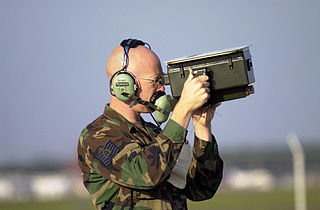
Identification, friend or foe (IFF) is a combat identification system designed for command and control. It uses a transponder that listens for an interrogation signal and then sends a response that identifies the broadcaster. IFF systems usually use radar frequencies, but other electromagnetic frequencies, radio or infrared, may be used. It enables military and civilian air traffic control interrogation systems to identify aircraft, vehicles or forces as friendly, as opposed to neutral or hostile, and to determine their bearing and range from the interrogator. IFF is used by both military and civilian aircraft. IFF was first developed during World War II, with the arrival of radar, and several friendly fire incidents.

<span class="mw-page-title-main">Distance measuring equipment</span> Radio navigation technology used in aviation

In aviation, distance measuring equipment (DME) is a radio navigation technology that measures the slant range (distance) between an aircraft and a ground station by timing the propagation delay of radio signals in the frequency band between 960 and 1215 megahertz (MHz). Line-of-visibility between the aircraft and ground station is required. An interrogator (airborne) initiates an exchange by transmitting a pulse pair, on an assigned 'channel', to the transponder ground station. The channel assignment specifies the carrier frequency and the spacing between the pulses. After a known delay, the transponder replies by transmitting a pulse pair on a frequency that is offset from the interrogation frequency by 63 MHz and having specified separation.

<span class="mw-page-title-main">H2S (radar)</span> First airborne, ground scanning radar system WWII

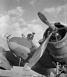
H2S was the first airborne, ground scanning radar system. It was developed for the Royal Air Force's Bomber Command during World War II to identify targets on the ground for night and all-weather bombing. This allowed attacks outside the range of the various radio navigation aids like Gee or Oboe, which were limited to about 350 kilometres (220 mi) of range from various base stations. It was also widely used as a general navigation system, allowing landmarks to be identified at long range.

<span class="mw-page-title-main">Naxos radar detector</span> Radar warning receiver in World War II

The Naxos radar warning receiver was a World War II German countermeasure to S band microwave radar produced by a cavity magnetron. Introduced in September 1943, it replaced Metox, which was incapable of detecting centimetric radar. Two versions were widely used, the FuG 350 Naxos Z that allowed night fighters to home in on H2S radars carried by RAF Bomber Command aircraft, and the FuMB 7 Naxos U for U-boats, offering early warning of the approach of RAF Coastal Command patrol aircraft equipped with ASV Mark III radar. A later model, Naxos ZR, provided warning of the approach of RAF night fighters equipped with AI Mk. VIII radar.

Gee-H, sometimes written G-H or GEE-H, was a radio navigation system developed by Britain during World War II to aid RAF Bomber Command. The name refers to the system's use of the earlier Gee equipment, as well as its use of the "H principle" or "twin-range principle" of location determination. Its official name was AMES Type 100.

Radar jamming and deception is a form of electronic countermeasures that intentionally sends out radio frequency signals to interfere with the operation of radar by saturating its receiver with noise or false information. Concepts that blanket the radar with signals so its display cannot be read are normally known as jamming, while systems that produce confusing or contradictory signals are known as deception, but it is also common for all such systems to be referred to as jamming.

<span class="mw-page-title-main">Secondary surveillance radar</span> Radar system used in air traffic control

Secondary surveillance radar (SSR) is a radar system used in air traffic control (ATC), that unlike primary radar systems that measure the bearing and distance of targets using the detected reflections of radio signals, relies on targets equipped with a radar transponder, that reply to each interrogation signal by transmitting encoded data such as an identity code, the aircraft's altitude and further information depending on its chosen mode. SSR is based on the military identification friend or foe (IFF) technology originally developed during World War II; therefore, the two systems are still compatible. Monopulse secondary surveillance radar (MSSR), Mode S, TCAS and ADS-B are similar modern methods of secondary surveillance.

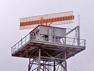
The air traffic control radar beacon system (ATCRBS) is a system used in air traffic control (ATC) to enhance surveillance radar monitoring and separation of air traffic. It consists of a rotating ground antenna and transponders in aircraft. The ground antenna sweeps a narrow vertical beam of microwaves around the airspace. When the beam strikes an aircraft, the transponder transmits a return signal back giving information such as altitude and the Squawk Code, a four digit code assigned to each aircraft that enters a region. Information about this aircraft is then entered into the system and subsequently added to the controller's screen to display this information when queried. This information can include flight number designation and altitude of the aircraft. ATCRBS assists air traffic control (ATC) surveillance radars by acquiring information about the aircraft being monitored, and providing this information to the radar controllers. The controllers can use the information to identify radar returns from aircraft and to distinguish those returns from ground clutter.

<span class="mw-page-title-main">Airport surveillance radar</span> Radar system

An airport surveillance radar (ASR) is a radar system used at airports to detect and display the presence and position of aircraft in the terminal area, the airspace around airports. It is the main air traffic control system for the airspace around airports. At large airports it typically controls traffic within a radius of 60 miles (96 km) of the airport below an elevation of 25,000 feet. The sophisticated systems at large airports consist of two different radar systems, the primary and secondary surveillance radar. The primary radar typically consists of a large rotating parabolic antenna dish that sweeps a vertical fan-shaped beam of microwaves around the airspace surrounding the airport. It detects the position and range of aircraft by microwaves reflected back to the antenna from the aircraft's surface. The secondary surveillance radar consists of a second rotating antenna, often mounted on the primary antenna, which interrogates the transponders of aircraft, which transmits a radio signal back containing the aircraft's identification, barometric altitude, and an emergency status code, which is displayed on the radar screen next to the return from the primary radar.

During World War II, the German Luftwaffe relied on an increasingly diverse array of electronic communications, IFF and RDF equipment as avionics in its aircraft and also on the ground. Most of this equipment received the generic prefix FuG for Funkgerät, meaning "radio equipment". Most of the aircraft-mounted Radar equipment also used the FuG prefix. This article is a list and a description of the radio, IFF and RDF equipment.

<span class="mw-page-title-main">AI Mark IV radar</span> Operational model of the worlds first air-to-air radar system

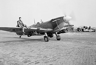
Radar, Airborne Interception, Mark IV, produced by USA as SCR-540, was the world's first operational air-to-air radar system. Early Mk. III units appeared in July 1940 on converted Bristol Blenheim light bombers, while the definitive Mk. IV reached widespread availability on the Bristol Beaufighter heavy fighter by early 1941. On the Beaufighter, the Mk. IV arguably played a role in ending the Blitz, the Luftwaffe's night bombing campaign of late 1940 and early 1941.

<span class="mw-page-title-main">AI Mark VIII radar</span> Type of air-to-air radar

Radar, Airborne Interception, Mark VIII, or AI Mk. VIII for short, was the first operational microwave-frequency air-to-air radar. It was used by Royal Air Force night fighters from late 1941 until the end of World War II. The basic concept, using a moving parabolic antenna to search for targets and track them accurately, remained in use by most airborne radars well into the 1980s.

<span class="mw-page-title-main">Airborne Interception radar</span>

Airborne Interception radar, or AI for short, is the British term for radar systems used to equip aircraft in air-to-air role. These radars are used primarily by Royal Air Force (RAF) and Fleet Air Arm night fighters and interceptors for locating and tracking other aircraft, although most AI radars could also be used in a number of secondary roles as well. The term was sometimes used generically for similar radars used in other countries.

<span class="mw-page-title-main">IFF Mark II</span> Aircraft identification system

IFF Mark II was the first operational identification friend or foe system. It was developed by the Royal Air Force just before the start of World War II. After a short run of prototype Mark Is, used experimentally in 1939, the Mark II began widespread deployment at the end of the Battle of Britain in late 1940. It remained in use until 1943, when it began to be replaced by the standardised IFF Mark III, which was used by all Allied aircraft until long after the war ended.

<span class="mw-page-title-main">IFF Mark III</span> Aircraft identification friend or foe system

IFF Mark III, also known as ARI.5025 in the UK or SCR.595 in the US, was the Allied Forces standard identification friend or foe (IFF) system from 1943 until well after the end of World War II. It was widely used by aircraft, ships, and submarines, as well as in various adaptations for secondary purposes like search and rescue. 500 units were also supplied to the Soviet Union during the war.

IFF Mark X was the NATO standard military identification friend or foe transponder system from the early 1950s until it was slowly replaced by the IFF Mark XII in the 1970s. It was also adopted by ICAO, with some modifications, as the civilian air traffic control (ATC) secondary radar (SSR) transponder. The X in the name does not mean "tenth", but "eXperimental". Later IFF models acted as if it was the tenth in the series and used subsequent numbers.

<span class="mw-page-title-main">ASV Mark II radar</span> Type of aircraft radar

Radar, Air-to-Surface Vessel, Mark II, or ASV Mk. II for short, was an airborne sea-surface search radar developed by the UK's Air Ministry immediately prior to the start of World War II. It was the first aircraft mounted radar of any sort to be used operationally. It was widely used by aircraft of the RAF Coastal Command, Fleet Air Arm and similar groups in the United States and Canada. A version was also developed for small ships, the Royal Navy's Type 286.

<span class="mw-page-title-main">ASV Mark III radar</span>

Radar, Air-to-Surface Vessel, Mark III, or ASV Mk. III for short, was a surface search radar system used by RAF Coastal Command during World War II. It was a slightly modified version of the H2S radar used by RAF Bomber Command, with minor changes to the antenna to make it more useful for the anti-submarine role. It was Coastal Command's primary radar from the spring of 1943 until the end of the war. Several improved versions were introduced, notably the ASV Mark VI, which replaced most Mk. IIIs from 1944 and ASV Mark VII radar, which saw only limited use until the post-war era.

References

Citations

  1. Hanbury Brown 1991, pp. 66–66.
  2. 1 2 Hanbury Brown 1991, p. 67.
  3. 1 2 Hanbury Brown 1991, p. 68.
  4. 1 2 Hanbury Brown 1991, p. 69.
  5. 1 2 Hanbury Brown 1991, p. 70.
  6. 1 2 Hanbury Brown 1991, p. 71.
  7. 1 2 3 Hanbury Brown 1991, p. 72.
  8. 1 2 Hanbury Brown 1991, p. 73.
  9. Hanbury Brown 1991, p. 74.
  10. "Pathfinders: In The Company of Strangers". IMDb.

Bibliography