When a fluid flows around an object, the fluid exerts a force on the object. Lift is the component of this force that is perpendicular to the oncoming flow direction. It contrasts with the drag force, which is the component of the force parallel to the flow direction. Lift conventionally acts in an upward direction in order to counter the force of gravity, but it is defined to act perpendicular to the flow and therefore can act in any direction.

A wing is a type of fin that produces lift while moving through air or some other fluid. Accordingly, wings have streamlined cross-sections that are subject to aerodynamic forces and act as airfoils. A wing's aerodynamic efficiency is expressed as its lift-to-drag ratio. The lift a wing generates at a given speed and angle of attack can be one to two orders of magnitude greater than the total drag on the wing. A high lift-to-drag ratio requires a significantly smaller thrust to propel the wings through the air at sufficient lift.
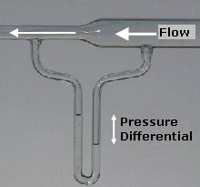
Bernoulli's principle is a key concept in fluid dynamics that relates pressure, speed and height. Bernoulli's principle states that an increase in the speed of a fluid occurs simultaneously with a decrease in static pressure or the fluid's potential energy. The principle is named after the Swiss mathematician and physicist Daniel Bernoulli, who published it in his book Hydrodynamica in 1738. Although Bernoulli deduced that pressure decreases when the flow speed increases, it was Leonhard Euler in 1752 who derived Bernoulli's equation in its usual form.

In fluid dynamics, a stall is a reduction in the lift coefficient generated by a foil as angle of attack increases. This occurs when the critical angle of attack of the foil is exceeded. The critical angle of attack is typically about 15°, but it may vary significantly depending on the fluid, foil, and Reynolds number.
In fluid dynamics, angle of attack is the angle between a reference line on a body and the vector representing the relative motion between the body and the fluid through which it is moving. Angle of attack is the angle between the body's reference line and the oncoming flow. This article focuses on the most common application, the angle of attack of a wing or airfoil moving through air.
In aeronautics, wave drag is a component of the aerodynamic drag on aircraft wings and fuselage, propeller blade tips and projectiles moving at transonic and supersonic speeds, due to the presence of shock waves. Wave drag is independent of viscous effects, and tends to present itself as a sudden and dramatic increase in drag as the vehicle increases speed to the critical Mach number. It is the sudden and dramatic rise of wave drag that leads to the concept of a sound barrier.

In aeronautics, the aspect ratio of a wing is the ratio of its span to its mean chord. It is equal to the square of the wingspan divided by the wing area. Thus, a long, narrow wing has a high aspect ratio, whereas a short, wide wing has a low aspect ratio.
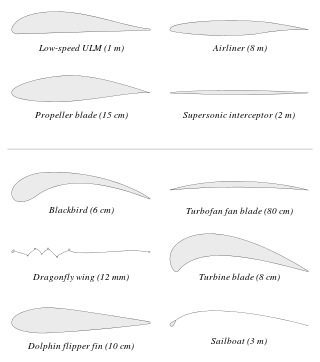
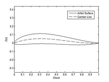
An airfoil or aerofoil is a streamlined body that is capable of generating significantly more lift than drag. Wings, sails and propeller blades are examples of airfoils. Foils of similar function designed with water as the working fluid are called hydrofoils.
In fluid dynamics, the lift coefficient is a dimensionless quantity that relates the lift generated by a lifting body to the fluid density around the body, the fluid velocity and an associated reference area. A lifting body is a foil or a complete foil-bearing body such as a fixed-wing aircraft. CL is a function of the angle of the body to the flow, its Reynolds number and its Mach number. The section lift coefficient cl refers to the dynamic lift characteristics of a two-dimensional foil section, with the reference area replaced by the foil chord.
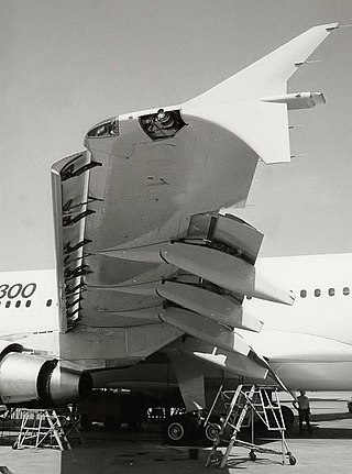
A flap is a high-lift device used to reduce the stalling speed of an aircraft wing at a given weight. Flaps are usually mounted on the wing trailing edges of a fixed-wing aircraft. Flaps are used to reduce the take-off distance and the landing distance. Flaps also cause an increase in drag so they are retracted when not needed.
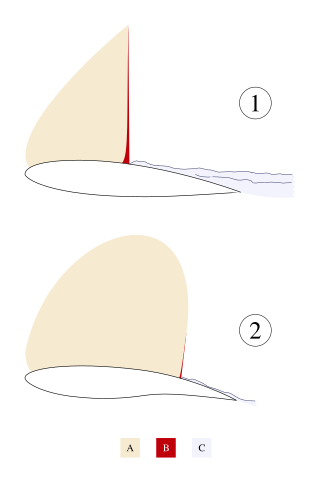
A supercritical aerofoil is an airfoil designed primarily to delay the onset of wave drag in the transonic speed range.
Variable camber is a feature of some of aircraft wings that changes the camber of the main aerofoil during flight.

The NACA airfoils are airfoil shapes for aircraft wings developed by the National Advisory Committee for Aeronautics (NACA). The shape of the NACA airfoils is described using a series of digits following the word "NACA". The parameters in the numerical code can be entered into equations to precisely generate the cross-section of the airfoil and calculate its properties.

Decalage on a fixed-wing aircraft is a measure of the relative incidences of wing surfaces. Various sources have defined it in multiple ways, depending on context:
- On a biplane, decalage can refer to the angle difference between the upper and lower wings, i.e. the acute angle contained between the chords of the wings in question.
- On other fixed-wing aircraft, decalage can refer to the difference in angle of the chord line of the wing and the chord line of the horizontal stabilizer. This is different from the angle of incidence, which refers to the angle of the wing chord to the longitudinal axis of the fuselage, without reference to the horizontal stabilizer.
The Kutta–Joukowski theorem is a fundamental theorem in aerodynamics used for the calculation of lift of an airfoil translating in a uniform fluid at a constant speed large enough so that the flow seen in the body-fixed frame is steady and unseparated. The theorem relates the lift generated by an airfoil to the speed of the airfoil through the fluid, the density of the fluid and the circulation around the airfoil. The circulation is defined as the line integral around a closed loop enclosing the airfoil of the component of the velocity of the fluid tangent to the loop. It is named after Martin Kutta and Nikolai Zhukovsky who first developed its key ideas in the early 20th century. Kutta–Joukowski theorem is an inviscid theory, but it is a good approximation for real viscous flow in typical aerodynamic applications.
The drag-divergence Mach number is the Mach number at which the aerodynamic drag on an airfoil or airframe begins to increase rapidly as the Mach number continues to increase. This increase can cause the drag coefficient to rise to more than ten times its low-speed value.
In flight dynamics, longitudinal stability is the stability of an aircraft in the longitudinal, or pitching, plane. This characteristic is important in determining whether an aircraft pilot will be able to control the aircraft in the pitching plane without requiring excessive attention or excessive strength.
A supersonic airfoil is a cross-section geometry designed to generate lift efficiently at supersonic speeds. The need for such a design arises when an aircraft is required to operate consistently in the supersonic flight regime.
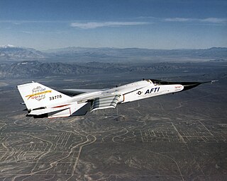
The General Dynamics–Boeing AFTI/F-111A Aardvark was a research aircraft modified from a General Dynamics F-111 Aardvark to test a Boeing-built supercritical mission adaptive wing (MAW). This MAW, in contrast to standard control surfaces, could smoothly change the shape of its airfoil in flight.

The dynamic stall is one of the hazardous phenomena on helicopter rotors, which can cause the onset of large torsional airloads and vibrations on the rotor blades. Unlike fixed-wing aircraft, of which the stall occurs at relatively low flight speed, the dynamic stall on a helicopter rotor emerges at high airspeeds or/and during manoeuvres with high load factors of helicopters, when the angle of attack(AOA) of blade elements varies intensively due to time-dependent blade flapping, cyclic pitch and wake inflow. For example, during forward flight at the velocity close to VNE, velocity, never exceed, the advancing and retreating blades almost reach their operation limits whereas flows are still attached to the blade surfaces. That is, the advancing blades operate at high Mach numbers so low values of AOA is needed but shock-induced flow separation may happen, while the retreating blade operates at much lower Mach numbers but the high values of AoA result in the stall.