Clutter (radar)

Last updated
Different radar artifacts cluttering the radar display Radar-artefacts2.PNG
Different radar artifacts cluttering the radar display

Clutter [1] [2] is a term used for unwanted echoes in electronic systems, particularly in reference to radars. Such echoes are typically returned from ground, sea, rain, animals/insects, chaff and atmospheric turbulences, and can cause serious performance issues with radar systems. What one person considers to be unwanted clutter, another may consider to be a wanted target. However, targets usually refer to point scatterers and clutter to extended scatterers (covering many range, angle, and Doppler cells). The clutter may fill a volume (such as rain) or be confined to a surface (like land). A knowledge of the volume or surface area illuminated is required to estimated the echo per unit volume, η, or echo per unit surface area, σ° (the radar backscatter coefficient).

Contents

Causes

Clutter may be caused by man-made objects such as buildings and — intentionally — by radar countermeasures such as chaff. Other causes include natural objects such as terrain features, sea, precipitation, hail spike, dust storms, birds, turbulence in the atmospheric circulation, and meteor trails. Radar clutter can also be caused by other atmospheric phenomena, such as disturbances in the ionosphere caused by geomagnetic storms or other space weather events. This phenomenon is especially apparent near the geomagnetic poles, where the action of the solar wind on the earth’s magnetosphere produces convection patterns in the ionospheric plasma. [3] Radar clutter can degrade the ability of over-the-horizon radar to detect targets. [3] [4] Clutter may also originate from multipath echoes from valid targets caused by ground reflection, atmospheric ducting or ionospheric reflection/refraction (e.g., anomalous propagation). This clutter type is especially bothersome since it appears to move and behave like common targets of interest, such as aircraft or weather balloons.

Clutter-limited or noise-limited radar

Electromagnetic signals processed by a radar receiver consist of three main components: useful signal (e.g., echoes from aircraft), clutter, and noise. The total signal competing with the target return is thus clutter plus noise. [5] In practice there is often either no clutter or clutter dominates and the noise can be ignored. In the first case, the radar is said to be noise-limited, while in the second it is clutter-limited.

Volume clutter

Figure 1. Illustration of illuminated Rain Cell Volume Clutter.PNG
Figure 1. Illustration of illuminated Rain Cell

Rain, hail, snow and chaff are examples of volume clutter. For example, suppose an airborne target, at range , is within a rainstorm. What is the effect on the detectability of the target?

First find the magnitude of the clutter return. Assume that the clutter fills the cell containing the target, that scatterers are statistically independent and that the scatterers are uniformly distributed through the volume. The clutter volume illuminated by a pulse can be calculated from the beam widths and the pulse duration, Figure 1. If c is the speed of light and is the time duration of the transmitted pulse then the pulse returning from a target is equivalent to a physical extent of c, as is the return from any individual element of the clutter. The azimuth and elevation beamwidths, at a range , are and respectively if the illuminated cell is assumed to have an elliptical cross section.

The volume of the illuminated cell is thus:

For small angles this simplifies to:

The clutter is assumed to be a large number of independent scatterers that fill the cell containing the target uniformly. The clutter return from the volume is calculated as for the normal radar equation but the radar cross section is replaced by the product of the volume backscatter coefficient, , and the clutter cell volume as derived above. The clutter return is then

where

A correction must be made to allow for the fact that the illumination of the clutter is not uniform across the beamwidth. In practice the beam shape will approximate to a sinc function which itself approximates to a Gaussian function. The correction factor is found by integrating across the beam width the Gaussian approximation of the antenna. The corrected back scattered power is

A number of simplifying substitutions can be made. The receiving antenna aperture is related to its gain by:

and the antenna gain is related to the two beamwidths by:

The same antenna is generally used both for transmission and reception thus the received clutter power is:

If the Clutter Return Power is greater than the System Noise Power then the Radar is clutter limited and the Signal to Clutter Ratio must be equal to or greater than the Minimum Signal to Noise Ratio for the target to be detectable.

From the radar equation the return from the target itself will be

with a resulting expression for the signal to clutter ratio of

The implication is that when the radar is noise limited the variation of signal to noise ratio is an inverse fourth power. Halving the distance will cause the signal to noise ratio to increase (improve) by a factor of 16. When the radar is volume clutter limited, however, the variation is an inverse square law and halving the distance will cause the signal to clutter to improve by only 4 times.

Since

it follows that

Clearly narrow beamwidths and short pulses are required to reduce the effect of clutter by reducing the volume of the clutter cell. If pulse compression is used then the appropriate pulse duration to be used in the calculation is that of the compressed pulse, not the transmitted pulse.

Problems in calculating signal to volume clutter ratio

A problem with volume clutter, e.g. rain, is that the volume illuminated may not be completely filled, in which case the fraction filled must be known, and the scatterers may not be uniformly distributed. Consider a beam 10° in elevation. At a range of 10 km the beam could cover from ground level to a height of 1750 metres. There could be rain at ground level but the top of the beam could be above cloud level. In the part of the beam containing rain the rainfall rate will not be constant. One would need to know how the rain was distributed to make any accurate assessment of the clutter and the signal to clutter ratio. All that can be expected from the equation is an estimate to the nearest 5 or 10 dB.

Surface clutter

The surface clutter return depends upon the nature of the surface, its roughness, the grazing angle (angle the beam makes with the surface), the frequency and the polarisation. The reflected signal is the phasor sum of a large number of individual returns from a variety of sources, some of them capable of movement (leaves, rain drops, ripples) and some of them stationary (pylons, buildings, tree trunks). Individual samples of clutter vary from one resolution cell to another (spatial variation) and vary with time for a given cell (temporal variation).

Beam filling

Figure 2. Illustration of high- and low-angle surface-clutter illumination Surface Clutter.png
Figure 2. Illustration of high- and low-angle surface-clutter illumination

For a target close to the Earth's surface such that the earth and target are in the same range resolution cell one of two conditions are possible. The most common case is when the beam intersects the surface at such an angle that the area illuminated at any one time is only a fraction of the surface intersected by the beam as illustrated in Figure 2.

Pulse length limited case

For the pulse length limited case the area illuminated depends upon the azimuth width of the beam and the length of the pulse, measured along the surface. The illuminated patch has a width in azimuth of

.

The length measured along the surface is

.

The area illuminated by the radar is then given by

For 'small' beamwidths this approximates to

The clutter return is then

Watts

Substituting for the illuminated area

Watts

where is the back scatter coefficient of the clutter. Converting to degrees and putting in the numerical values gives

Watts

The expression for the target return remains unchanged thus the signal to clutter ratio is

Watts

This simplifies to

In the case of surface clutter the signal to clutter now varies inversely with R. Halving the distance only causes a doubling of the ratio (a factor of two improvement).

Problems in calculating clutter for the pulse length limited case

There are a number of problems in calculating the signal to clutter ratio. The clutter in the main beam is extended over a range of grazing angles and the backscatter coefficient depends upon grazing angle. Clutter will appear in the antenna sidelobes, which again will involve a range of grazing angles and may even involve clutter of a different nature.

Beam width limited case

The calculation is similar to the previous examples, in this case the illuminated area is

which for small beamwidths simplifies to

The clutter return is as before

Watts

Substituting for the illuminated area

Watts

This can be simplified to:

Watts

Converting to degrees

Watts

The target return remains unchanged thus

Which simplifies to

As in the case of Volume Clutter the Signal to clutter ratio follows an inverse square law.

General problems in calculating surface clutter

The general significant problem is that the backscatter coefficient cannot in general be calculated and must be measured. The problem is the validity of measurements taken in one location under one set of conditions being used for a different location under different conditions. Various empirical formulae and graphs exist which enable an estimate to be made but the results need to be used with caution.

Clutter folding

Clutter folding is a term used in describing "clutter" seen by radar systems. Clutter folding becomes a problem when the range extent of the clutter (seen by the radar) exceeds the pulse repetition frequency interval of the radar, and it no longer provides adequate clutter suppression, and the clutter "folds" back in range. The solution to this problem is usually to add fill pulses to each coherent dwell of the radar, increasing the range over which clutter suppression is applied by the system.

The tradeoff for doing this is that adding fill pulses will degrade the performance, due to wasted transmitter power and a longer dwell time.

Related Research Articles

Linear elasticity is a mathematical model of how solid objects deform and become internally stressed due to prescribed loading conditions. It is a simplification of the more general nonlinear theory of elasticity and a branch of continuum mechanics.

<span class="mw-page-title-main">Weierstrass elliptic function</span> Class of mathematical functions

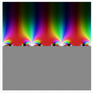
In mathematics, the Weierstrass elliptic functions are elliptic functions that take a particularly simple form. They are named for Karl Weierstrass. This class of functions are also referred to as ℘-functions and they are usually denoted by the symbol ℘, a uniquely fancy script p. They play an important role in the theory of elliptic functions. A ℘-function together with its derivative can be used to parameterize elliptic curves and they generate the field of elliptic functions with respect to a given period lattice.

<span class="mw-page-title-main">Klein–Nishina formula</span> Electron-photon scattering cross section

In particle physics, the Klein–Nishina formula gives the differential cross section of photons scattered from a single free electron, calculated in the lowest order of quantum electrodynamics. It was first derived in 1928 by Oskar Klein and Yoshio Nishina, constituting one of the first successful applications of the Dirac equation. The formula describes both the Thomson scattering of low energy photons and the Compton scattering of high energy photons, showing that the total cross section and expected deflection angle decrease with increasing photon energy.

<span class="mw-page-title-main">Chiral model</span> Model of mesons in the massless quark limit

In nuclear physics, the chiral model, introduced by Feza Gürsey in 1960, is a phenomenological model describing effective interactions of mesons in the chiral limit (where the masses of the quarks go to zero), but without necessarily mentioning quarks at all. It is a nonlinear sigma model with the principal homogeneous space of a Lie group as its target manifold. When the model was originally introduced, this Lie group was the SU(N), where N is the number of quark flavors. The Riemannian metric of the target manifold is given by a positive constant multiplied by the Killing form acting upon the Maurer–Cartan form of SU(N).

A cyclostationary process is a signal having statistical properties that vary cyclically with time. A cyclostationary process can be viewed as multiple interleaved stationary processes. For example, the maximum daily temperature in New York City can be modeled as a cyclostationary process: the maximum temperature on July 21 is statistically different from the temperature on December 20; however, it is a reasonable approximation that the temperature on December 20 of different years has identical statistics. Thus, we can view the random process composed of daily maximum temperatures as 365 interleaved stationary processes, each of which takes on a new value once per year.

<span class="mw-page-title-main">Directivity</span> Measure of how much of an antennas signal is transmitted in one direction

In electromagnetics, directivity is a parameter of an antenna or optical system which measures the degree to which the radiation emitted is concentrated in a single direction. It is the ratio of the radiation intensity in a given direction from the antenna to the radiation intensity averaged over all directions. Therefore, the directivity of a hypothetical isotropic radiator is 1, or 0 dBi.

The Newman–Penrose (NP) formalism is a set of notation developed by Ezra T. Newman and Roger Penrose for general relativity (GR). Their notation is an effort to treat general relativity in terms of spinor notation, which introduces complex forms of the usual variables used in GR. The NP formalism is itself a special case of the tetrad formalism, where the tensors of the theory are projected onto a complete vector basis at each point in spacetime. Usually this vector basis is chosen to reflect some symmetry of the spacetime, leading to simplified expressions for physical observables. In the case of the NP formalism, the vector basis chosen is a null tetrad: a set of four null vectors—two real, and a complex-conjugate pair. The two real members often asymptotically point radially inward and radially outward, and the formalism is well adapted to treatment of the propagation of radiation in curved spacetime. The Weyl scalars, derived from the Weyl tensor, are often used. In particular, it can be shown that one of these scalars— in the appropriate frame—encodes the outgoing gravitational radiation of an asymptotically flat system.

In the Newman–Penrose (NP) formalism of general relativity, Weyl scalars refer to a set of five complex scalars which encode the ten independent components of the Weyl tensor of a four-dimensional spacetime.

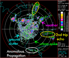
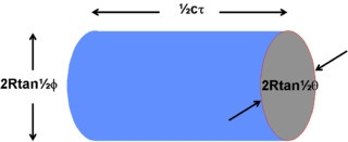
Radar engineering details are technical details pertaining to the components of a radar and their ability to detect the return energy from moving scatterers — determining an object's position or obstruction in the environment. This includes field of view in terms of solid angle and maximum unambiguous range and velocity, as well as angular, range and velocity resolution. Radar sensors are classified by application, architecture, radar mode, platform, and propagation window.

The Scherrer equation, in X-ray diffraction and crystallography, is a formula that relates the size of sub-micrometre crystallites in a solid to the broadening of a peak in a diffraction pattern. It is often referred to, incorrectly, as a formula for particle size measurement or analysis. It is named after Paul Scherrer. It is used in the determination of size of crystals in the form of powder.

In mathematics, an elliptic hypergeometric series is a series Σcn such that the ratio cn/cn−1 is an elliptic function of n, analogous to generalized hypergeometric series where the ratio is a rational function of n, and basic hypergeometric series where the ratio is a periodic function of the complex number n. They were introduced by Date-Jimbo-Kuniba-Miwa-Okado (1987) and Frenkel & Turaev (1997) in their study of elliptic 6-j symbols.

<span class="mw-page-title-main">Modular lambda function</span>

In mathematics, the modular lambda function λ(τ) is a highly symmetric Holomorphic function on the complex upper half-plane. It is invariant under the fractional linear action of the congruence group Γ(2), and generates the function field of the corresponding quotient, i.e., it is a Hauptmodul for the modular curve X(2). Over any point τ, its value can be described as a cross ratio of the branch points of a ramified double cover of the projective line by the elliptic curve , where the map is defined as the quotient by the [−1] involution.

In general relativity, the Vaidya metric describes the non-empty external spacetime of a spherically symmetric and nonrotating star which is either emitting or absorbing null dusts. It is named after the Indian physicist Prahalad Chunnilal Vaidya and constitutes the simplest non-static generalization of the non-radiative Schwarzschild solution to Einstein's field equation, and therefore is also called the "radiating(shining) Schwarzschild metric".

Laser linewidth is the spectral linewidth of a laser beam.

The table of chords, created by the Greek astronomer, geometer, and geographer Ptolemy in Egypt during the 2nd century AD, is a trigonometric table in Book I, chapter 11 of Ptolemy's Almagest, a treatise on mathematical astronomy. It is essentially equivalent to a table of values of the sine function. It was the earliest trigonometric table extensive enough for many practical purposes, including those of astronomy. Since the 8th and 9th centuries, the sine and other trigonometric functions have been used in Islamic mathematics and astronomy, reforming the production of sine tables. Khwarizmi and Habash al-Hasib later produced a set of trigonometric tables.

In optics, the Fraunhofer diffraction equation is used to model the diffraction of waves when the diffraction pattern is viewed at a long distance from the diffracting object, and also when it is viewed at the focal plane of an imaging lens.

<span class="mw-page-title-main">Two-ray ground-reflection model</span>

The two-rays ground-reflection model is a multipath radio propagation model which predicts the path losses between a transmitting antenna and a receiving antenna when they are in line of sight (LOS). Generally, the two antenna each have different height. The received signal having two components, the LOS component and the reflection component formed predominantly by a single ground reflected wave.

In plasma physics and magnetic confinement fusion, neoclassical transport or neoclassical diffusion is a theoretical description of collisional transport in toroidal plasmas, usually found in tokamaks or stellerators. It is a modification of classical diffusion adding in effects of non-uniform magnetic fields due to the toroidal geometry, which give rise to new diffusion effects.

The fracture of soft materials involves large deformations and crack blunting before propagation of the crack can occur. Consequently, the stress field close to the crack tip is significantly different from the traditional formulation encountered in the Linear elastic fracture mechanics. Therefore, fracture analysis for these applications requires a special attention. The Linear Elastic Fracture Mechanics (LEFM) and K-field are based on the assumption of infinitesimal deformation, and as a result are not suitable to describe the fracture of soft materials. However, LEFM general approach can be applied to understand the basics of fracture on soft materials. The solution for the deformation and crack stress field in soft materials considers large deformation and is derived from the finite strain elastostatics framework and hyperelastic material models.

In theoretical physics, more specifically in quantum field theory and supersymmetry, supersymmetric Yang–Mills, also known as super Yang–Mills and abbreviated to SYM, is a supersymmetric generalization of Yang–Mills theory, which is a gauge theory that plays an important part in the mathematical formulation of forces in particle physics.

References

  1. Golbon-Haghighi, M.H.; Zhang G. (July 2019). "Detection of Ground Clutter for Dual-Polarization Weather Radar Using a Novel 3D Discriminant Function". Journal of Atmospheric and Oceanic Technology. 36 (7): 1285–1296. Bibcode:2019JAtOT..36.1285G. doi: 10.1175/JTECH-D-18-0147.1 .
  2. Golbon-Haghighi, M.H.; Zhang G.; Li Y.; Doviak R. (June 2016). "Detection of Ground Clutter from Weather Radar Using a Dual-Polarization and Dual-Scan Method". Atmosphere. 7 (6): 83. Bibcode:2016Atmos...7...83G. doi: 10.3390/atmos7060083 .
  3. 1 2 Riddolls, Ryan J (December 2006). A Canadian Perspective on High-Frequency Over-the-Horizon Radar (PDF) (Technical report). Ottawa, Ontario, Canada: Defence Research and Development Canada. p. 38. DRDC Ottawa TM 2006-285. Retrieved 2 December 2023.
  4. Elkins, TJ (March 1980). A model for high frequency radar auroral clutter (PDF) (Technical report). RADC Technical Reports. Vol. 1980. Rome, New York: Rome Air Development Center. p. 9. RADC-TR-80-122. Retrieved 2 December 2023.
  5. "Radar Clutter | SKYbrary Aviation Safety".