A machine is a mechanical structure that uses power to apply forces and control movement to perform an intended action. Machines can be driven by animals and people, by natural forces such as wind and water, and by chemical, thermal, or electrical power, and include a system of mechanisms that shape the actuator input to achieve a specific application of output forces and movement. They can also include computers and sensors that monitor performance and plan movement, often called mechanical systems.

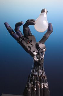
An industrial robot is a robot system used for manufacturing. Industrial robots are automated, programmable and capable of movement on three or more axis.

Inverse kinematics is the mathematical process of recovering the movements of an object in the world from some other data, such as a film of those movements, or a film of the world as seen by a camera which is itself making those movements. This is useful in robotics and in film animation.
Robot kinematics applies geometry to the study of the movement of multi-degree of freedom kinematic chains that form the structure of robotic systems. The emphasis on geometry means that the links of the robot are modeled as rigid bodies and its joints are assumed to provide pure rotation or translation.
A four-bar linkage, also called a four-bar, is the simplest movable closed chain linkage. It consists of four bodies, called bars or links, connected in a loop by four joints. Generally, the joints are configured so the links move in parallel planes, and the assembly is called a planar four-bar linkage. Spherical and spatial four-bar linkages also exist and are used in practice.
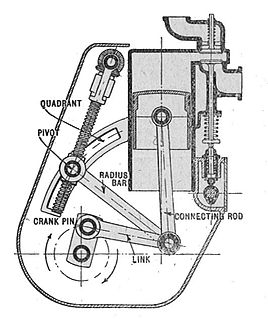
A mechanical linkage is an assembly of bodies connected to manage forces and movement. The movement of a body, or link, is studied using geometry so the link is considered to be rigid. The connections between links are modeled as providing ideal movement, pure rotation or sliding for example, and are called joints. A linkage modeled as a network of rigid links and ideal joints is called a kinematic chain.
In physics, the degree of freedom (DOF) of a mechanical system is the number of independent parameters that define its configuration. It is the number of parameters that determine the state of a physical system and is important to the analysis of systems of bodies in mechanical engineering, aeronautical engineering, robotics, and structural engineering.
An overconstrained mechanism is a linkage that has more degrees of freedom than is predicted by the mobility formula. The mobility formula evaluates the degree of freedom of a system of rigid bodies that results when constraints are imposed in the form of joints connecting the links.

Serial manipulators are the most common industrial robots and they are designed as a series of links connected by motor-actuated joints that extend from a base to an end-effector. Often they have an anthropomorphic arm structure described as having a "shoulder", an "elbow", and a "wrist".
A kinematic pair is a connection between two bodies that imposes constraints on their relative movement. Franz Reuleaux introduced the kinematic pair as a new approach to the study of machines that provided an advance over the motion of elements consisting of simple machines.

In mechanical engineering, a kinematic chain is an assembly of rigid bodies connected by joints to provide constrained motion that is the mathematical model for a mechanical system. As in the familiar use of the word chain, the rigid bodies, or links, are constrained by their connections to other links. An example is the simple open chain formed by links connected in series, like the usual chain, which is the kinematic model for a typical robot manipulator.
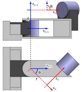
There are many conventions used in the robotics research field. This article summarises these conventions.

In engineering, a mechanism is a device that transforms input forces and movement into a desired set of output forces and movement. Mechanisms generally consist of moving components that can include:
Kinematics equations are the constraint equations of a mechanical system such as a robot manipulator that define how input movement at one or more joints specifies the configuration of the device, in order to achieve a task position or end-effector location. Kinematics equations are used to analyze and design articulated systems ranging from four-bar linkages to serial and parallel robots.
The Robotics Toolbox is MATLAB Toolbox software that supports research and teaching into arm-type and mobile robotics. This is free software but requires the proprietary MATLAB environment in order to execute. A subset of functions have been ported to GNU Octave and Python. The Toolbox forms the basis of the exercises in several textbooks
Actin is a software toolkit for designing, simulating, and controlling robots, created by the American firm Energid Technologies of Cambridge, Massachusetts. In addition to their headquarters in the United States, the firm opened an office in India to sell Actin in Asia.
The product of exponentials (POE) method is a robotics convention for mapping the links of a spatial kinematic chain. It is an alternative to Denavit–Hartenberg parameterization. While the latter method uses the minimal number of parameters to represent joint motions, the former method has a number of advantages: uniform treatment of prismatic and revolute joints, definition of only two reference frames, and an easy geometric interpretation from the use of screw axes for each joint.