Curved mirror

Last updated
Reflections in a convex mirror. The photographer is seen reflected at top right Mirror.globe.arp.500pix.jpg
Reflections in a convex mirror. The photographer is seen reflected at top right

A curved mirror is a mirror with a curved reflecting surface. The surface may be either convex (bulging outward) or concave (recessed inward). Most curved mirrors have surfaces that are shaped like part of a sphere, but other shapes are sometimes used in optical devices. The most common non-spherical type are parabolic reflectors, found in optical devices such as reflecting telescopes that need to image distant objects, since spherical mirror systems, like spherical lenses, suffer from spherical aberration. Distorting mirrors are used for entertainment. They have convex and concave regions that produce deliberately distorted images. They also provide highly magnified or highly diminished (smaller) images when the object is placed at certain distances.

Contents

Convex mirrors

A convex mirror diagram showing the focus, focal length, centre of curvature, principal axis, etc. Convex mirror1.svg
A convex mirror diagram showing the focus, focal length, centre of curvature, principal axis, etc.

A convex mirror or diverging mirror is a curved mirror in which the reflective surface bulges towards the light source. [1] Convex mirrors reflect light outwards, therefore they are not used to focus light. Such mirrors always form a virtual image, since the focal point (F) and the centre of curvature (2F) are both imaginary points "inside" the mirror, that cannot be reached. As a result, images formed by these mirrors cannot be projected on a screen, since the image is inside the mirror. The image is smaller than the object, but gets larger as the object approaches the mirror.

A collimated (parallel) beam of light diverges (spreads out) after reflection from a convex mirror, since the normal to the surface differs at each spot on the mirror.

Uses of convex mirrors

Convex mirror lets motorists see around a corner. 2008-03-14 Convex mirror in Atlanta garage entrance.jpg
Convex mirror lets motorists see around a corner.
Detail of the convex mirror in the Arnolfini Portrait The Arnolfini Portrait, detail (2).jpg
Detail of the convex mirror in the Arnolfini Portrait

The passenger-side mirror on a car is typically a convex mirror. In some countries, these are labeled with the safety warning "Objects in mirror are closer than they appear", to warn the driver of the convex mirror's distorting effects on distance perception. Convex mirrors are preferred in vehicles because they give an upright (not inverted), though diminished (smaller), image and because they provide a wider field of view as they are curved outwards.

These mirrors are often found in the hallways of various buildings (commonly known as "hallway safety mirrors"), including hospitals, hotels, schools, stores, and apartment buildings. They are usually mounted on a wall or ceiling where hallways intersect each other, or where they make sharp turns. They are useful for people to look at any obstruction they will face on the next hallway or after the next turn. They are also used on roads, driveways, and alleys to provide safety for road users where there is a lack of visibility, especially at curves and turns. [2]

Convex mirrors are used in some automated teller machines as a simple and handy security feature, allowing the users to see what is happening behind them. Similar devices are sold to be attached to ordinary computer monitors. Convex mirrors make everything seem smaller but cover a larger area of surveillance.

Round convex mirrors called Oeil de Sorcière (French for "sorcerer's eye") were a popular luxury item from the 15th century onwards, shown in many depictions of interiors from that time. [3] With 15th century technology, it was easier to make a regular curved mirror (from blown glass) than a perfectly flat one. They were also known as "bankers' eyes" due to the fact that their wide field of vision was useful for security. Famous examples in art include the Arnolfini Portrait by Jan van Eyck and the left wing of the Werl Altarpiece by Robert Campin. [4]

Convex mirror image

A virtual image in a Christmas bauble. UserRedCoat.JPG
A virtual image in a Christmas bauble.

The image on a convex mirror is always virtual (rays haven't actually passed through the image; their extensions do, like in a regular mirror), diminished (smaller), and upright (not inverted). As the object gets closer to the mirror, the image gets larger, until approximately the size of the object, when it touches the mirror. As the object moves away, the image diminishes in size and gets gradually closer to the focus, until it is reduced to a point in the focus when the object is at an infinite distance. These features make convex mirrors very useful: since everything appears smaller in the mirror, they cover a wider field of view than a normal plane mirror, so useful for looking at cars behind a driver's car on a road, watching a wider area for surveillance, etc.

Effect on image of object's position relative to mirror focal point (convex)
Object's position (S),
focal point (F)
ImageDiagram
  • Virtual
  • Upright
  • Reduced (diminished/smaller)
Convexmirror raydiagram.svg

Concave mirrors

A concave mirror diagram showing the focus, focal length, centre of curvature, principal axis, etc. Concave mirror.svg
A concave mirror diagram showing the focus, focal length, centre of curvature, principal axis, etc.

A concave mirror, or converging mirror, has a reflecting surface that is recessed inward (away from the incident light). Concave mirrors reflect light inward to one focal point. They are used to focus light. Unlike convex mirrors, concave mirrors show different image types depending on the distance between the object and the mirror.

The mirrors are called "converging mirrors" because they tend to collect light that falls on them, refocusing parallel incoming rays toward a focus. This is because the light is reflected at different angles at different spots on the mirror as the normal to the mirror surface differs at each spot.

Uses of concave mirrors

Concave mirrors are used in reflecting telescopes. [5] They are also used to provide a magnified image of the face for applying make-up or shaving. [6] In illumination applications, concave mirrors are used to gather light from a small source and direct it outward in a beam as in torches, headlamps and spotlights, or to collect light from a large area and focus it into a small spot, as in concentrated solar power. Concave mirrors are used to form optical cavities, which are important in laser construction. Some dental mirrors use a concave surface to provide a magnified image. The mirror landing aid system of modern aircraft carriers also uses a concave mirror.

Concave mirror image

Effect on image of object's position relative to mirror focal point (concave)
Object's position (S),
focal point (F)
Nature of ImageDiagram

(Object between focal point and mirror)
  • Virtual
  • Upright
  • Magnified (larger)
Concavemirror raydiagram F.svg

(Object at focal point)
  • Reflected rays are parallel and never meet, so no image is formed.
  • In the limit where S approaches F, the image distance approaches infinity, and the image can be either real or virtual and either upright or inverted depending on whether S approaches F from its left or right side.
Concavemirror raydiagram FE.svg

(Object between focus and centre of curvature)
  • Real image
  • Inverted (vertically)
  • Magnified (larger)
Concavemirror raydiagram 2FE.svg

(Object at centre of curvature)
  • Real image
  • Inverted (vertically)
  • Same size
  • Image formed at centre of curvature
Image-Concavemirror raydiagram 2F F.svg

(Object beyond centre of curvature)
  • Real image
  • Inverted (vertically)
  • Reduced (diminished/smaller)
  • As the distance of the object increases, the image asymptotically approaches the focal point
  • In the limit where S approaches infinity, the image size approaches zero as the image approaches F
Concavemirror raydiagram 2F.svg

Mirror shape

Most curved mirrors have a spherical profile. [7] These are the simplest to make, and it is the best shape for general-purpose use. Spherical mirrors, however, suffer from spherical aberration—parallel rays reflected from such mirrors do not focus to a single point. For parallel rays, such as those coming from a very distant object, a parabolic reflector can do a better job. Such a mirror can focus incoming parallel rays to a much smaller spot than a spherical mirror can. A toroidal reflector is a form of parabolic reflector which has a different focal distance depending on the angle of the mirror.

Analysis

Mirror equation, magnification, and focal length

The Gaussian mirror equation, also known as the mirror and lens equation, relates the object distance and image distance to the focal length : [2]

.

The sign convention used here is that the focal length is positive for concave mirrors and negative for convex ones, and and are positive when the object and image are in front of the mirror, respectively. (They are positive when the object or image is real.) [2]

For convex mirrors, if one moves the term to the right side of the equation to solve for , then the result is always a negative number, meaning that the image distance is negative—the image is virtual, located "behind" the mirror. This is consistent with the behavior described above.

For concave mirrors, whether the image is virtual or real depends on how large the object distance is compared to the focal length. If the term is larger than the term, then is positive and the image is real. Otherwise, the term is negative and the image is virtual. Again, this validates the behavior described above.

The magnification of a mirror is defined as the height of the image divided by the height of the object:

.

By convention, if the resulting magnification is positive, the image is upright. If the magnification is negative, the image is inverted (upside down).

Ray tracing

The image location and size can also be found by graphical ray tracing, as illustrated in the figures above. A ray drawn from the top of the object to the mirror surface vertex (where the optical axis meets the mirror) will form an angle with the optical axis. The reflected ray has the same angle to the axis, but on the opposite side (See Specular reflection).

A second ray can be drawn from the top of the object, parallel to the optical axis. This ray is reflected by the mirror and passes through its focal point. The point at which these two rays meet is the image point corresponding to the top of the object. Its distance from the optical axis defines the height of the image, and its location along the axis is the image location. The mirror equation and magnification equation can be derived geometrically by considering these two rays. A ray that goes from the top of the object through the focal point can be considered instead. Such a ray reflects parallel to the optical axis and also passes through the image point corresponding to the top of the object.

Ray transfer matrix of spherical mirrors

The mathematical treatment is done under the paraxial approximation, meaning that under the first approximation a spherical mirror is a parabolic reflector. The ray matrix of a concave spherical mirror is shown here. The element of the matrix is , where is the focal point of the optical device.

Spherical mirror.png

Boxes 1 and 3 feature summing the angles of a triangle and comparing to π radians (or 180°). Box 2 shows the Maclaurin series of up to order 1. The derivations of the ray matrices of a convex spherical mirror and a thin lens are very similar.

See also

Related Research Articles

<span class="mw-page-title-main">Optical aberration</span> Deviation from perfect paraxial optical behavior

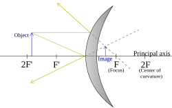
In optics, aberration is a property of optical systems, such as lenses, that causes light to be spread out over some region of space rather than focused to a point. Aberrations cause the image formed by a lens to be blurred or distorted, with the nature of the distortion depending on the type of aberration. Aberration can be defined as a departure of the performance of an optical system from the predictions of paraxial optics. In an imaging system, it occurs when light from one point of an object does not converge into a single point after transmission through the system. Aberrations occur because the simple paraxial theory is not a completely accurate model of the effect of an optical system on light, rather than due to flaws in the optical elements.

<span class="mw-page-title-main">Lens</span> Optical device which transmits and refracts light

A lens is a transmissive optical device that focuses or disperses a light beam by means of refraction. A simple lens consists of a single piece of transparent material, while a compound lens consists of several simple lenses (elements), usually arranged along a common axis. Lenses are made from materials such as glass or plastic and are ground, polished, or molded to the required shape. A lens can focus light to form an image, unlike a prism, which refracts light without focusing. Devices that similarly focus or disperse waves and radiation other than visible light are also called "lenses", such as microwave lenses, electron lenses, acoustic lenses, or explosive lenses.

<span class="mw-page-title-main">Optics</span> Branch of physics that studies light

Optics is the branch of physics that studies the behaviour and properties of light, including its interactions with matter and the construction of instruments that use or detect it. Optics usually describes the behaviour of visible, ultraviolet, and infrared light. Light is a type of electromagnetic radiation, and other forms of electromagnetic radiation such as X-rays, microwaves, and radio waves exhibit similar properties.

<span class="mw-page-title-main">Parabola</span> Plane curve: conic section

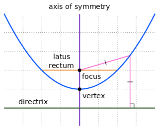
In mathematics, a parabola is a plane curve which is mirror-symmetrical and is approximately U-shaped. It fits several superficially different mathematical descriptions, which can all be proved to define exactly the same curves.

<span class="mw-page-title-main">Numerical aperture</span> Characteristic of an optical system

In optics, the numerical aperture (NA) of an optical system is a dimensionless number that characterizes the range of angles over which the system can accept or emit light. By incorporating index of refraction in its definition, NA has the property that it is constant for a beam as it goes from one material to another, provided there is no refractive power at the interface. The exact definition of the term varies slightly between different areas of optics. Numerical aperture is commonly used in microscopy to describe the acceptance cone of an objective, and in fiber optics, in which it describes the range of angles within which light that is incident on the fiber will be transmitted along it.

The focal length of an optical system is a measure of how strongly the system converges or diverges light; it is the inverse of the system's optical power. A positive focal length indicates that a system converges light, while a negative focal length indicates that the system diverges light. A system with a shorter focal length bends the rays more sharply, bringing them to a focus in a shorter distance or diverging them more quickly. For the special case of a thin lens in air, a positive focal length is the distance over which initially collimated (parallel) rays are brought to a focus, or alternatively a negative focal length indicates how far in front of the lens a point source must be located to form a collimated beam. For more general optical systems, the focal length has no intuitive meaning; it is simply the inverse of the system's optical power.

<span class="mw-page-title-main">Parabolic reflector</span> Reflector that has the shape of a paraboloid

A parabolicreflector is a reflective surface used to collect or project energy such as light, sound, or radio waves. Its shape is part of a circular paraboloid, that is, the surface generated by a parabola revolving around its axis. The parabolic reflector transforms an incoming plane wave travelling along the axis into a spherical wave converging toward the focus. Conversely, a spherical wave generated by a point source placed in the focus is reflected into a plane wave propagating as a collimated beam along the axis.

<span class="mw-page-title-main">Ritchey–Chrétien telescope</span> Specialized Cassegrain telescope

A Ritchey–Chrétien telescope is a specialized variant of the Cassegrain telescope that has a hyperbolic primary mirror and a hyperbolic secondary mirror designed to eliminate off-axis optical errors (coma). The RCT has a wider field of view free of optical errors compared to a more traditional reflecting telescope configuration. Since the mid 20th century, a majority of large professional research telescopes have been Ritchey–Chrétien configurations; some well-known examples are the Hubble Space Telescope, the Keck telescopes and the ESO Very Large Telescope.

<span class="mw-page-title-main">Spherical aberration</span> Optical aberration

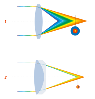
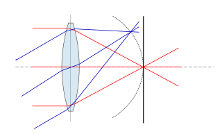
In optics, spherical aberration (SA) is a type of aberration found in optical systems that have elements with spherical surfaces. Lenses and curved mirrors are prime examples, because this shape is easier to manufacture. Light rays that strike a spherical surface off-centre are refracted or reflected more or less than those that strike close to the centre. This deviation reduces the quality of images produced by optical systems. The effect of spherical aberration was first identified by Ibn al-Haytham who discussed it in his work Kitāb al-Manāẓir.

<span class="mw-page-title-main">Optical telescope</span> Telescope for observations with visible light

An optical telescope is a telescope that gathers and focuses light mainly from the visible part of the electromagnetic spectrum, to create a magnified image for direct visual inspection, to make a photograph, or to collect data through electronic image sensors.

<span class="mw-page-title-main">Reflecting telescope</span> Telescopes which utilize curved mirrors to form an image

A reflecting telescope is a telescope that uses a single or a combination of curved mirrors that reflect light and form an image. The reflecting telescope was invented in the 17th century by Isaac Newton as an alternative to the refracting telescope which, at that time, was a design that suffered from severe chromatic aberration. Although reflecting telescopes produce other types of optical aberrations, it is a design that allows for very large diameter objectives. Almost all of the major telescopes used in astronomy research are reflectors. Many variant forms are in use and some employ extra optical elements to improve image quality or place the image in a mechanically advantageous position. Since reflecting telescopes use mirrors, the design is sometimes referred to as a catoptric telescope.

<span class="mw-page-title-main">Magnification</span> Process of enlarging the apparent size of something

Magnification is the process of enlarging the apparent size, not physical size, of something. This enlargement is quantified by a size ratio called optical magnification. When this number is less than one, it refers to a reduction in size, sometimes called de-magnification.

<span class="mw-page-title-main">Specular reflection</span> Mirror-like wave reflection

Specular reflection, or regular reflection, is the mirror-like reflection of waves, such as light, from a surface.

Geometrical optics, or ray optics, is a model of optics that describes light propagation in terms of rays. The ray in geometrical optics is an abstraction useful for approximating the paths along which light propagates under certain circumstances.

<span class="mw-page-title-main">Eyepiece</span> Type of lens attached to a variety of optical devices such as telescopes and microscopes

An eyepiece, or ocular lens, is a type of lens that is attached to a variety of optical devices such as telescopes and microscopes. It is named because it is usually the lens that is closest to the eye when someone looks through an optical device to observe an object or sample. The objective lens or mirror collects light from an object or sample and brings it to focus creating an image of the object. The eyepiece is placed near the focal point of the objective to magnify this image to the eyes. The amount of magnification depends on the focal length of the eyepiece.

<span class="mw-page-title-main">Abbe sine condition</span> Design rule for optical systems

In optics, the Abbe sine condition is a condition that must be fulfilled by a lens or other optical system in order for it to produce sharp images of off-axis as well as on-axis objects. It was formulated by Ernst Abbe in the context of microscopes.

<span class="mw-page-title-main">Cassegrain reflector</span> Combination of concave and convex mirrors

The Cassegrain reflector is a combination of a primary concave mirror and a secondary convex mirror, often used in optical telescopes and radio antennas, the main characteristic being that the optical path folds back onto itself, relative to the optical system's primary mirror entrance aperture. This design puts the focal point at a convenient location behind the primary mirror and the convex secondary adds a telephoto effect creating a much longer focal length in a mechanically short system.

<span class="mw-page-title-main">Thin lens</span> Lens with a thickness that is negligible

In optics, a thin lens is a lens with a thickness that is negligible compared to the radii of curvature of the lens surfaces. Lenses whose thickness is not negligible are sometimes called thick lenses.

<span class="mw-page-title-main">Plane mirror</span> Mirror with a flat reflecting surface

A plane mirror is a mirror with a flat (planar) reflective surface. For light rays striking a plane mirror, the angle of reflection equals the angle of incidence. The angle of the incidence is the angle between the incident ray and the surface normal. Therefore, the angle of reflection is the angle between the reflected ray and the normal and a collimated beam of light does not spread out after reflection from a plane mirror, except for diffraction effects.

<span class="mw-page-title-main">Petzval field curvature</span> Optical aberration

Petzval field curvature, named for Joseph Petzval, describes the optical aberration in which a flat object normal to the optical axis cannot be brought properly into focus on a flat image plane. Field curvature can be corrected with the use of a field flattener, designs can also incorporate a curved focal plane like in the case of the human eye in order to improve image quality at the focal surface.

References

  1. Nayak, Sanjay K.; Bhuvana, K.P. (2012). Engineering Physics. New Delhi: Tata McGraw-Hill Education. p. 6.4. ISBN   9781259006449.
  2. 1 2 3 Hecht, Eugene (1987). "5.4.3". Optics (2nd ed.). Addison Wesley. pp. 160–1. ISBN   0-201-11609-X.
  3. Venice Botteghe: Antiques, Bijouterie, Coffee, Cakes, Carpet, Glass Archived 2017-03-06 at the Wayback Machine
  4. Lorne Campbell, National Gallery Catalogues (new series): The Fifteenth Century Netherlandish Paintings, pp. 178-179, 188-189, 1998, ISBN   1-85709-171-X
  5. Joshi, Dhiren M. Living Science Physics 10. Ratna Sagar. ISBN   9788183322904. Archived from the original on 2018-01-18.
  6. Sura's Year Book 2006 (English). Sura Books. ISBN   9788172541248. Archived from the original on 2018-01-18.
  7. Al-Azzawi, Abdul (2006-12-26). Light and Optics: Principles and Practices. CRC Press. ISBN   9780849383144. Archived from the original on 2018-01-18.