Electrical cable

Last updated
Electrical cable diagram Leitungsende Abisoliert en.svg
Electrical cable diagram
Flexible mains cable with three 2.5 mm solid copper conductors Electric guide 3x2.5 mm.jpg
Flexible mains cable with three 2.5 mm solid copper conductors

An electrical cable is an assembly of one or more wires running side by side or bundled, which is used as an electrical conductor to carry electric current.

Contents

Electrical cables are used to connect two or more devices, enabling the transfer of electrical signals or power from one device to the other. Physically, an electrical cable is an assembly consisting of one or more conductors with their own insulations and optional screens, individual coverings, assembly protection and protective covering.

One or more electrical cables and their corresponding connectors may be formed into a cable assembly, [1] which is not necessarily suitable for connecting two devices but can be a partial product (e.g. to be soldered onto a printed circuit board with a connector mounted to the housing). Cable assemblies can also take the form of a cable tree or cable harness, used to connect many terminals together.

Uses

6 inch (15 cm) outside diameter, oil-cooled cables, traversing the Grand Coulee Dam throughout. An example of a heavy cable for power transmission. 6 inch cable.jpg
6 inch (15 cm) outside diameter, oil-cooled cables, traversing the Grand Coulee Dam throughout. An example of a heavy cable for power transmission.
Fire test in Sweden, showing fire rapidly spreading through the burning of cable insulation, a phenomenon of great importance for cables used in some installations. Cable tray fire sweden.jpg
Fire test in Sweden, showing fire rapidly spreading through the burning of cable insulation, a phenomenon of great importance for cables used in some installations.
500,000 circular mil (254 mm ) single conductor power cable 500mcm cable jacket marking.jpg
500,000 circular mil (254 mm ) single conductor power cable

Electrical cables are used to connect two or more devices, enabling the transfer of electrical signals or power from one device to the other. Long-distance communication takes place over undersea communication cables. Power cables are used for bulk transmission of alternating and direct current power, especially using high-voltage cable. Electrical cables are extensively used in building wiring for lighting, power and control circuits permanently installed in buildings. Since all the circuit conductors required can be installed in a cable at one time, installation labor is saved compared to certain other wiring methods.

Physically, an electrical cable is an assembly consisting of one or more conductors with their own insulations and optional screens, individual coverings, assembly protection and protective coverings. Electrical cables may be made more flexible by stranding the wires. In this process, smaller individual wires are twisted or braided together to produce larger wires that are more flexible than solid wires of similar size. Bunching small wires before concentric stranding adds the most flexibility. Copper wires in a cable may be bare, or they may be plated with a thin layer of another metal, most often tin but sometimes gold, silver or some other material. Tin, gold, and silver are much less prone to oxidation than copper, which may lengthen wire life, and makes soldering easier. Tinning is also used to provide lubrication between strands. Tinning was used to help removal of rubber insulation. Tight lays during stranding makes the cable extensible (CBA – as in telephone handset cords).[ further explanation needed ]

In the 19th century and early 20th century, electrical cable was often insulated using cloth, rubber or paper. Plastic materials are generally used today, except for high-reliability[ clarification needed ] power cables. The first thermoplastic used was gutta-percha (a natural latex) which was found useful for underwater cables in the 19th century. The first, and still very common, man-made plastic used for cable insulation was polyethylene. This was invented in 1930, but not available outside military use until after World War 2 during which a telegraph cable using it was laid across the English Channel to support troops following D-Day. [2]

Cables can be securely fastened and organized, such as by using trunking, cable trays, cable ties or cable lacing. Continuous-flex or flexible cables used in moving applications within cable carriers can be secured using strain relief devices or cable ties.

At high frequencies, current tends to run along the surface of the conductor. This is known as the skin effect.

Characteristics

Coaxial cable Coaxial cable cutaway.svg
Coaxial cable
Twisted pair cabling USB Twisted Pair.svg
Twisted pair cabling

Any current-carrying conductor, including a cable, radiates an electromagnetic field. Likewise, any conductor or cable will pick up energy from any existing electromagnetic field around it. These effects are often undesirable, in the first case amounting to unwanted transmission of energy which may adversely affect nearby equipment or other parts of the same piece of equipment; and in the second case, unwanted pickup of noise which may mask the desired signal being carried by the cable, or, if the cable is carrying power supply or control voltages, pollute them to such an extent as to cause equipment malfunction.

The first solution to these problems is to keep cable lengths in buildings short since pick up and transmission are essentially proportional to the length of the cable. The second solution is to route cables away from trouble. Beyond this, there are particular cable designs that minimize electromagnetic pickup and transmission. Three of the principal design techniques are shielding, coaxial geometry, and twisted-pair geometry.

Shielding makes use of the electrical principle of the Faraday cage. The cable is encased for its entire length in foil or wire mesh. All wires running inside this shielding layer will be to a large extent decoupled from external electrical fields, particularly if the shield is connected to a point of constant voltage, such as earth or ground. Simple shielding of this type is not greatly effective against low-frequency magnetic fields, however - such as magnetic "hum" from a nearby power transformer. A grounded shield on cables operating at 2.5 kV or more gathers leakage current and capacitive current, protecting people from electric shock and equalizing stress on the cable insulation.

Coaxial design helps to further reduce low-frequency magnetic transmission and pickup. In this design the foil or mesh shield has a circular cross section and the inner conductor is exactly at its center. This causes the voltages induced by a magnetic field between the shield and the core conductor to consist of two nearly equal magnitudes which cancel each other.

A twisted pair has two wires of a cable twisted around each other. This can be demonstrated by putting one end of a pair of wires in a hand drill and turning while maintaining moderate tension on the line. Where the interfering signal has a wavelength that is long compared to the pitch of the twisted pair, alternate lengths of wires develop opposing voltages, tending to cancel the effect of the interference.

Fire protection

Electrical cable jacket material is usually constructed of flexible plastic which will burn. The fire hazard of grouped cables can be significant. [3] Cables jacketing materials can be formulated to prevent fire spread [4] (see Mineral-insulated copper-clad cable). Alternately, fire spread amongst combustible cables can be prevented by the application of fire retardant coatings directly on the cable exterior, [5] or the fire threat can be isolated by the installation of boxes constructed of noncombustible materials around the bulk cable installation.

Types

A 250 V, 16 A electrical cable on a reel ElectricWireOnReel.JPG
A 250 V, 16 A electrical cable on a reel

CENELEC HD 361 is a ratified standard published by CENELEC, which relates to wire and cable marking type, whose goal is to harmonize cables. Deutsches Institut für Normung (DIN, VDE) has released a similar standard (DIN VDE 0292).

See also

Related Research Articles

<span class="mw-page-title-main">Insulator (electricity)</span> Material that does not conduct an electric current

An electrical insulator is a material in which electric current does not flow freely. The atoms of the insulator have tightly bound electrons which cannot readily move. Other materials—semiconductors and conductors—conduct electric current more easily. The property that distinguishes an insulator is its resistivity; insulators have higher resistivity than semiconductors or conductors. The most common examples are non-metals.

<span class="mw-page-title-main">Wire</span> Single, usually cylindrical, flexible strand or bar or rod of metal

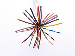
A wire is a flexible, round, bar of metal.

In telecommunications and professional audio, a balanced line or balanced signal pair is an electrical circuit consisting of two conductors of the same type, both of which have equal impedances along their lengths, to ground, and to other circuits. The primary advantage of the balanced line format is good rejection of common-mode noise and interference when fed to a differential device such as a transformer or differential amplifier.

<span class="mw-page-title-main">Alternating current</span> Electric current that periodically reverses direction

Alternating current (AC) is an electric current that periodically reverses direction and changes its magnitude continuously with time, in contrast to direct current (DC), which flows only in one direction. Alternating current is the form in which electric power is delivered to businesses and residences, and it is the form of electrical energy that consumers typically use when they plug kitchen appliances, televisions, fans and electric lamps into a wall socket. The abbreviations AC and DC are often used to mean simply alternating and direct, respectively, as when they modify current or voltage.

<span class="mw-page-title-main">Coaxial cable</span> Electrical cable type with concentric inner conductor, insulator, and conducting shield

Coaxial cable, or coax, is a type of electrical cable consisting of an inner conductor surrounded by a concentric conducting shield, with the two separated by a dielectric ; many coaxial cables also have a protective outer sheath or jacket. The term coaxial refers to the inner conductor and the outer shield sharing a geometric axis.

<span class="mw-page-title-main">Twisted pair</span> Type of wiring used for communications

Twisted pair cabling is a type of communications cable in which two conductors of a single circuit are twisted together for the purposes of improving electromagnetic compatibility. Compared to a single conductor or an untwisted balanced pair, a twisted pair reduces electromagnetic radiation from the pair and crosstalk between neighbouring pairs and improves rejection of external electromagnetic interference. It was invented by Alexander Graham Bell.

<span class="mw-page-title-main">Electrical connector</span> Device used to join electrical conductors

Components of an electrical circuit are electrically connected if an electric current can run between them through an electrical conductor. An electrical connector is an electromechanical device used to create an electrical connection between parts of an electrical circuit, or between different electrical circuits, thereby joining them into a larger circuit.

<span class="mw-page-title-main">Balun</span> Electrical device

A balun is an electrical device that allows balanced and unbalanced lines to be interfaced without disturbing the impedance arrangement of either line. A balun can take many forms and may include devices that also transform impedances but need not do so. Sometimes, in the case of transformer baluns, they use magnetic coupling but need not do so. Common-mode chokes are also used as baluns and work by eliminating, rather than rejecting, common mode signals.

Electrical wiring in North America follows the regulations and standards applicable at the installation location. It is also designed to provide proper function, and is also influenced by history and traditions of the location installation.

In an electrical system, a ground loop or earth loop occurs when two points of a circuit are intended to have the same ground reference potential but instead have a different potential between them. This is typically caused when enough current is flowing in the connection between the two ground points to produce a voltage drop and cause two points to be at different potentials. Current may be produced in a circular ground connection by electromagnetic induction.

<span class="mw-page-title-main">Electrical wiring</span> Electrical installation of cabling

Electrical wiring is an electrical installation of cabling and associated devices such as switches, distribution boards, sockets, and light fittings in a structure.

<span class="mw-page-title-main">Overhead power line</span> Above-ground structure for bulk transfer and distribution of electricity

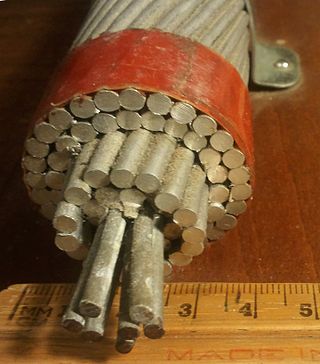
An overhead power line is a structure used in electric power transmission and distribution to transmit electrical energy along large distances. It consists of one or more conductors suspended by towers or poles. Since the surrounding air provides good cooling, insulation along long passages and allows optical inspection, overhead power lines are generally the lowest-cost method of power transmission for large quantities of electric energy.

<span class="mw-page-title-main">Power cable</span> Bundle of wires for transmitting electricity

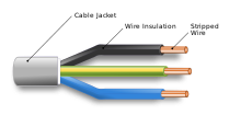
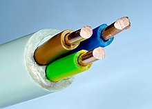
A power cable is an electrical cable, an assembly of one or more electrical conductors, usually held together with an overall sheath. The assembly is used for transmission of electrical power. Power cables may be installed as permanent wiring within buildings, buried in the ground, run overhead, or exposed. Power cables that are bundled inside thermoplastic sheathing and that are intended to be run inside a building are known as NM-B.

<span class="mw-page-title-main">Shielded cable</span> Electric cable with metal jacket (shield) to prevent magnetic interference

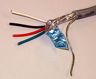
A shielded cable or screened cable is an electrical cable that has a common conductive layer around its conductors for electromagnetic shielding. This shield is usually covered by an outermost layer of the cable. Common types of cable shielding can most broadly be categorized as foil type, contraspiralling wire strands or both. A longitudinal wire may be necessary with dielectric spiral foils to short out each turn.

<span class="mw-page-title-main">Unbalanced line</span>

In telecommunications and electrical engineering in general, an unbalanced line is a pair of conductors intended to carry electrical signals, which have unequal impedances along their lengths and to ground and other circuits. Examples of unbalanced lines are coaxial cable or the historic earth return system invented for the telegraph, but rarely used today. Unbalanced lines are to be contrasted with balanced lines, such as twin-lead or twisted pair which use two identical conductors to maintain impedance balance throughout the line. Balanced and unbalanced lines can be interfaced using a device called a balun.

<span class="mw-page-title-main">Transformer types</span> Overview of electrical transformer types

A variety of types of electrical transformer are made for different purposes. Despite their design differences, the various types employ the same basic principle as discovered in 1831 by Michael Faraday, and share several key functional parts.

<span class="mw-page-title-main">High-voltage cable</span> Cable used for electric power transmission at high voltage

A high-voltage cable is a cable used for electric power transmission at high voltage. A cable includes a conductor and insulation. Cables are considered to be fully insulated. This means that they have a fully rated insulation system that will consist of insulation, semi-con layers, and a metallic shield. This is in contrast to an overhead line, which may include insulation but not fully rated for operating voltage. High-voltage cables of differing types have a variety of applications in instruments, ignition systems, and alternating current (AC) and direct current (DC) power transmission. In all applications, the insulation of the cable must not deteriorate due to the high-voltage stress, ozone produced by electric discharges in air, or tracking. The cable system must prevent contact of the high-voltage conductor with other objects or persons, and must contain and control leakage current. Cable joints and terminals must be designed to control the high-voltage stress to prevent the breakdown of the insulation.

<span class="mw-page-title-main">Copper conductor</span> Electrical wire or other conductor made of copper

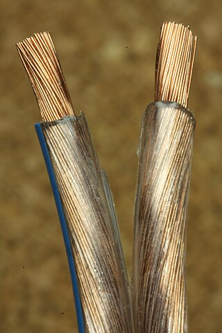
Copper has been used in electrical wiring since the invention of the electromagnet and the telegraph in the 1820s. The invention of the telephone in 1876 created further demand for copper wire as an electrical conductor.

This glossary of electrical and electronics engineering is a list of definitions of terms and concepts related specifically to electrical engineering and electronics engineering. For terms related to engineering in general, see Glossary of engineering.

References

  1. "What Is a Cable Assembly?". wiseGEEK. Retrieved 1 July 2019.
  2. Ash, Stewart, "The development of submarine cables", ch. 1 in, Burnett, Douglas R.; Beckman, Robert; Davenport, Tara M., Submarine Cables: The Handbook of Law and Policy, Martinus Nijhoff Publishers, 2014 ISBN   9789004260320.
  3. Krause, Fritz; Schmidt, Willard (2 Jan 1982). "Burn Mode Analysis of Horizontal Cable Tray Fires". Systems Safety Technology Division, Sandia National Laboratories. NUREG/CR-2431, SAND81-0079.
  4. NFPA 72 National Electrical Code. 2017. pp. 648, 800.179(A).
  5. Vytenis, Babrauskas (12 Jan 1981). "Fire Performance of Wire and Cable". Building and Fire Research Laboratory, NIST: 56.
  6. 1 2 "Electrical Wiring FAQ (Part 2 of 2)Section - What is Romex/NM/NMD? What is BX? When should I use each?". faqs.org.

Further reading