Typical heat flux plate, HFP01. This sensor is typically used in the measurement of the thermal resistance of and heat flux on building envelopes (walls, roofs). Also, this sensor type can be dug in to measure soil heat flux. Diameter 80 mmHeat flux sensor mounted on a window. Heat flux sensors can be used like this to determine the R-value or U-value of building envelope materials while they are still installed in buildings.
A heat flux sensor is a transducer that generates an electrical signal proportional to the total heat rate applied to the surface of the sensor. The measured heat rate is divided by the surface area of the sensor to determine the heat flux.
Silicon encased heat flux sensor for measurements on rugged surfaces
The heat flux can have different origins; in principle convective, radiative as well as conductive heat can be measured. Heat flux sensors are known under different names, such as heat flux transducers, heat flux gauges, or heat flux plates. Some instruments are actually single-purpose heat flux sensors, like pyranometers for solar radiation measurement. Other heat flux sensors include Gardon gauges[1] (also known as a circular-foil gauge), thin-film thermopiles,[2] and Schmidt-Boelter gauges.[3]
Usage
Heat flux sensors are used for a variety of applications. Common applications are studies of building envelope thermal resistance, studies of the effect of fire and flames or laser power measurements. More exotic applications include estimation of fouling on boiler surfaces, temperature measurement of moving foil material, etc.
The total heat flux is composed of a conductive, convective and radiative part. Depending on the application, one might want to measure all three of these quantities or single one out.
An example of measurement of conductive heat flux is a heat flux plate incorporated into a wall.
An example of measurement of radiative heat flux density is a pyranometer for measurement of solar radiation.
An example of a sensor sensitive to radiative as well as convective heat flux is a Gardon or Schmidt–Boelter gauge, used for studies of fire and flames. The Gardon must measure convection perpendicular to the face of the sensor to be accurate due to the circular-foil construction, while the wire-wound geometry of the Schmidt-Boelter gauge can measure both perpendicular and parallel flows. In this case the sensor is mounted on a water-cooled body. Such sensors are used in fire resistance testing to put the fire to which samples are exposed to the right intensity level.
There are various examples of sensors that internally use heat flux sensors examples are laser power meters, pyranometers, etc.
We will discuss three large fields of application in what follows.[4]
Applications in meteorology and agriculture
Soil heat flux is a most important parameter in agro-meteorological studies, since it allows one to study the amount of energy stored in the soil as a function of time.
Typically, two or three sensors are buried in the ground around a meteorological station at a depth of around 4cm below the surface. The problems that are encountered in soil are threefold:
First is the fact that the thermal properties of the soil are constantly changing by absorption and subsequent evaporation of water.
Second, the flow of water through the soil also represents a flow of energy, going together with a thermal shock, which often is misinterpreted by conventional sensors.
The third aspect of soil is that by the constant process of wetting and drying and by the animals living on the soil, the quality of the contact between sensor and soil is not known.
The result of all this is the quality of the data in soil heat flux measurement is not under control; the measurement of soil heat flux is considered to be extremely difficult.
Applications in building physics
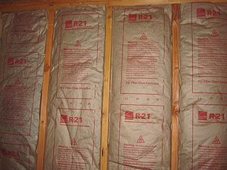
In a world ever more concerned with saving energy, studying the thermal properties of buildings has become a growing field of interest. One of the starting points in these studies is the mounting of heat flux sensors on walls in existing buildings or structures built especially for this type of research. Heat flux sensors mounted to building walls or envelope component can monitor the amount of heat energy loss/gain through that component and/or can be used to measure the envelope thermal resistance, R-value, or thermal transmittance, U-value.
The measurement of heat flux in walls is comparable to that in soil in many respects. Two major differences however are the fact that the thermal properties of a wall generally do not change (provided its moisture content does not change) and that it is not always possible to insert the heat flux sensor in the wall, so that it has to be mounted on its inner or outer surface. When the heat flux sensor has to be mounted on the surface of the wall, one has to take care that the added thermal resistance is not too large. Also, the spectral properties should be matching those of the wall as closely as possible. If the sensor is exposed to solar radiation, this is especially important. In this case one should consider painting the sensor in the same color as the wall. Also, in walls the use of self-calibrating heat flux sensors should be considered.[5]
Applications in medical studies
The measurement of the heat exchange of human beings is of importance for medical studies, and when designing clothing, immersion suits and sleeping bags.[6]
A difficulty during this measurement is that the human skin is not particularly suitable for the mounting of heat flux sensors. Also, the sensor has to be thin: the skin essentially is a constant temperature heat sink, so added thermal resistance has to be avoided. Another problem is that test persons might be moving. The contact between the test person and the sensor can be lost. For this reason, whenever a high level of quality assurance of the measurement is required, it can be recommended to use a self-calibrating sensor.
Special heat flux solutions are used in highly transient temperatures changes. These gauges called Thermocouple MCT, allow the measurement of highly transient surface temperatures. For example, they are typical for testing wind tunnel models in impulse facilities, the change of the cylinder wall temperature during one cycle of a combustion engine, all types of industrial applications, and research-oriented work where the registration of highly transient temperatures is of importance. The response time of the gauges has been proven to be in the range of a few microseconds. The output of all gauges represents the time-dependent temperature of its measuring part which in this case may significantly deviate from the temperature of the gauge-surrounding heating or cooling environment. For example, in a piston engine a flush wall-mounted temperature gauge registers with its typical response time the variation of the cylinder wall temperature and not the variation of the average gas temperature within the cylinder. The measured time-dependent surface temperature of the gauge and its known thermal properties allow to recalculate the time-dependent heat flux from the heating environment onto the gauge which caused the temperature change of the gauge. This is accomplished by the theory of heat conduction into a semi-infinite body. The design of the gauges is such that during a typical time period of about 10 ms, the requirements of a body of semi-infinite thickness are fulfilled. The direction of the deduced heat flux is perpendicular to the measuring surface of the gauge.
Properties
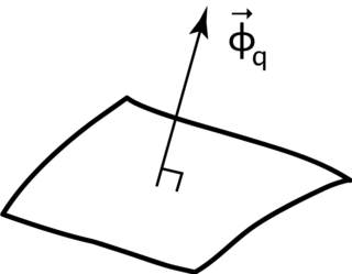
A heat flux sensor should measure the local heat flux density in one direction. The result is expressed in watts per square meter. The calculation is done according to:
Where is the sensor output and is the calibration constant, specific for the sensor.
General characteristics of a heat flux sensor
As shown before in the figure to the left, heat flux sensors generally have the shape of a flat plate and a sensitivity in the direction perpendicular to the sensor surface.
Usually, a number of thermocouples connected in series called thermopiles are used. General advantages of thermopiles are their stability, low ohmic value (which implies little pickup of electromagnetic disturbances), good signal-noise ratio and the fact that zero input gives zero output. Disadvantageous is the low sensitivity.
For better understanding of heat flux sensor behavior, it can be modeled as a simple electrical circuit consisting of a resistance, , and a capacitor, . In this way it can be seen that one can attribute a thermal resistance , a thermal capacity and also a response time to the sensor.
Usually, the thermal resistance and the thermal capacity of the entire heat flux sensor are equal to those of the filling material. Stretching the analogy with the electric circuit further, one arrives at the following expression for the response time:
In which is the sensor thickness, the density, the specific heat capacity and the thermal conductivity. From this formula one can conclude that material properties of the filling material and dimensions are determining the response time. As a rule of thumb, the response time is proportional to the thickness to the power of two.
Gardon or Schmidt Boelter gauge showing the instrument main components: metal body, black sensor, water cooling pipe in and out, mounting flange, and cable. Dimensions: diameter housing is 25mm. Photo shows model SBG01.
Other parameters that are determining sensor properties are the electrical characteristics of the thermocouple. The temperature dependence of the thermocouple causes the temperature dependence and the non-linearity of the heat flux sensor. The non-linearity at a certain temperature is in fact the derivative of the temperature dependence at that temperature.
However, a well-designed sensor may have a lower temperature dependence and better linearity than expected. There are two ways of achieving this:
As a first possibility, the thermal dependence of conductivity of the filling material and of the thermocouple material can be used to counterbalance the temperature dependence of the voltage that is generated by the thermopile.
Another possibility to minimize the temperature dependence of a heat flux sensor, is to use a resistance network with an incorporated thermistor. The temperature dependence of the thermistor will balance the temperature dependence of the thermopile.
Another factor that determines heat flux sensor behavior, is the construction of the sensor. In particular some designs have a strongly nonuniform sensitivity. Others even exhibit a sensitivity to lateral fluxes. The sensor schematically given in the above figure would for example also be sensitive to heat flows from left to right. This type of behavior will not cause problems as long as fluxes are uniform and in one direction only.
Sandwich construction
To promote uniformity of sensitivity, a so-called sandwich construction as shown in the figure to the left can be used. The purpose of the plates, which have a high conductivity, is to promote the transport of heat across the whole sensitive surface.
It is difficult to quantify non-uniformity and sensitivity to lateral fluxes. Some sensors are equipped with an extra electrical lead, splitting the sensor into two parts. If during application, there is non-uniform behavior of the sensor or the flux, this will result in different outputs of the two parts.
Summarizing: The intrinsic specifications that can be attributed to heat flux sensors are thermal conductivity, total thermal resistance, heat capacity, response time, non-linearity, stability, temperature dependence of sensitivity, uniformity of sensitivity and sensitivity to lateral fluxes. For the latter two specifications, a good method for quantification is not known.
Calibration of thin heat flux transducers
In order to do in-situ measurements, the user must be provided with the correct calibration constant . This constant is also called sensitivity. The sensitivity is primarily determined by the sensor construction and operation temperatures, but also by the geometry and material properties of the object that is measured. Therefore, the sensor should be calibrated under conditions that are close to the conditions of the intended application. The calibration set-up should also be properly shielded to limit external influences.
Preparation
To do a calibration measurement, one needs a voltmeter or datalogger with resolution of ±2μV or better. One should avoid air gaps between layers in the test stack. These can be filled with filling materials, like toothpaste, caulk or putty. If need be, thermally conductive gel can be used to improve contact between layers.[7] A temperature sensor should be placed on or near the sensor and connected to a readout device.
Measuring
The calibration is done by applying a controlled heat flux through the sensor. By varying the hot and cold sides of the stack, and measuring the voltages of the heat flux sensor and temperature sensor, the correct sensitivity can be determined with:
where is the sensor output and is the known heat flux through the sensor.
If the sensor is mounted onto a surface and is exposed to convection and radiation during the expected applications, the same conditions should be taken into account during calibration.
Doing measurements at different temperatures allows for determining sensitivity as a function of the temperature.
In-situ calibration
FHF04SC is a self-calibrating version of the flexible FHF04 heat flux sensor. Sensors that are embedded in construction can sometimes be very troublesome to remove if they need to be re-calibrated (in a lab). Some sensors incorporate heaters in order to be able to leave the sensor in place while performing a re-calibration.
While heat flux sensors are typically supplied with a sensitivity by the manufacturer, there are times and situations that call for a re-calibration of the sensor. Especially in building walls or envelopes the heat flux sensors cannot be removed after the initial installation or may be very difficult to reach. In order to calibrate the sensor, some come with an integrated heater with specified characteristics. By applying a known voltage on and current through the heater, a controlled heat flux is provided which can be used to calculate the new sensitivity.
Error sources
The interpretation of measurement results of heat flux sensors is often done assuming that the phenomenon that is studied, is quasi-static and taking place in a direction transversal to the sensor surface. Dynamic effects and lateral fluxes are possible error sources.
Dynamic effects
The assumption that conditions are quasi-static should be related to the response time of the detector.
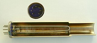
Heat flux sensor as radiation detector
The case that the heat flux sensor is used as a radiation detector (see figure to the left) will serve to illustrate the effect of changing fluxes. Assuming that the cold joints of the sensor are at a constant temperature, and an energy flows from , the sensor response is:
This shows that one should expect a false reading during a period that equals several response times, . Generally, heat flux sensors are quite slow and will need several minutes to reach 95% response. This is the reason why one prefers to work with values that are integrated over a long period; during this period the sensor signal will go up and down. The assumption is that errors due to long response times will cancel. The upgoing signal will give an error, the downgoing signal will produce an equally large error with a different sign. This will be valid only if periods with stable heat flow prevail.
In order to avoid errors caused by long response times, one should use sensors with low value of , since this product determines the response time. In other words: sensors with low mass or small thickness.
The sensor response time equation above holds as long as the cold joints are at a constant temperature. An unexpected result shows when the temperature of the sensor changes.
Assuming that the sensor temperature starts changing at the cold joints, at a rate of , starting at , is the sensor response time, the reaction to this is:
Pressure measurement is the measurement of an applied force by a fluid on a surface. Pressure is typically measured in units of force per unit of surface area. Many techniques have been developed for the measurement of pressure and vacuum. Instruments used to measure and display pressure mechanically are called pressure gauges,vacuum gauges or compound gauges. The widely used Bourdon gauge is a mechanical device, which both measures and indicates and is probably the best known type of gauge.
A thermocouple, also known as a "thermoelectrical thermometer", is an electrical device consisting of two dissimilar electrical conductors forming an electrical junction. A thermocouple produces a temperature-dependent voltage as a result of the Seebeck effect, and this voltage can be interpreted to measure temperature. Thermocouples are widely used as temperature sensors.
A thermistor is a semiconductor type of resistor whose resistance is strongly dependent on temperature, more so than in standard resistors. The word thermistor is a portmanteau of thermal and resistor.
A calorimeter is a device used for calorimetry, or the process of measuring the heat of chemical reactions or physical changes as well as heat capacity. Differential scanning calorimeters, isothermal micro calorimeters, titration calorimeters and accelerated rate calorimeters are among the most common types. A simple calorimeter just consists of a thermometer attached to a metal container full of water suspended above a combustion chamber. It is one of the measurement devices used in the study of thermodynamics, chemistry, and biochemistry.
In the context of construction, the R-value is a measure of how well a two-dimensional barrier, such as a layer of insulation, a window or a complete wall or ceiling, resists the conductive flow of heat. R-value is the temperature difference per unit of heat flux needed to sustain one unit of heat flux between the warmer surface and colder surface of a barrier under steady-state conditions. The measure is therefore equally relevant for lowering energy bills for heating in the winter, for cooling in the summer, and for general comfort.
A strain gauge is a device used to measure strain on an object. Invented by Edward E. Simmons and Arthur C. Ruge in 1938, the most common type of strain gauge consists of an insulating flexible backing which supports a metallic foil pattern. The gauge is attached to the object by a suitable adhesive, such as cyanoacrylate. As the object is deformed, the foil is deformed, causing its electrical resistance to change. This resistance change, usually measured using a Wheatstone bridge, is related to the strain by the quantity known as the gauge factor.
A thermopile is an electronic device that converts thermal energy into electrical energy. It is composed of several thermocouples connected usually in series or, less commonly, in parallel. Such a device works on the principle of the thermoelectric effect, i.e., generating a voltage when its dissimilar metals (thermocouples) are exposed to a temperature difference.
A pyranometer is a type of actinometer used for measuring solar irradiance on a planar surface and it is designed to measure the solar radiation flux density (W/m2) from the hemisphere above within a wavelength range 0.3 μm to 3 μm.
A pyrgeometer is a device that measures near-surface infra-red (IR) radiation, approximately from 4.5 μm to 100 μm on the electromagnetic spectrum.
The concept of mean radiant temperature (MRT) is used to quantify the exchange of radiant heat between a human and their surrounding environment, with a view to understanding the influence of surface temperatures on personal comfort. Mean radiant temperature has been both qualitatively defined and quantitatively evaluated for both indoor and outdoor environments.
Resistance thermometers, also called resistance temperature detectors (RTDs), are sensors used to measure temperature. Many RTD elements consist of a length of fine wire wrapped around a heat-resistant ceramic or glass core but other constructions are also used. The RTD wire is a pure material, typically platinum (Pt), nickel (Ni), or copper (Cu). The material has an accurate resistance/temperature relationship which is used to provide an indication of temperature. As RTD elements are fragile, they are often housed in protective probes.
A spectroradiometer is a light measurement tool that is able to measure both the wavelength and amplitude of the light emitted from a light source. Spectrometers discriminate the wavelength based on the position the light hits at the detector array allowing the full spectrum to be obtained with a single acquisition. Most spectrometers have a base measurement of counts which is the un-calibrated reading and is thus impacted by the sensitivity of the detector to each wavelength. By applying a calibration, the spectrometer is then able to provide measurements of spectral irradiance, spectral radiance and/or spectral flux. This data is also then used with built in or PC software and numerous algorithms to provide readings or Irradiance (W/cm2), Illuminance, Radiance (W/sr), Luminance (cd), Flux, Chromaticity, Color Temperature, Peak and Dominant Wavelength. Some more complex spectrometer software packages also allow calculation of PAR μmol/m2/s, Metamerism, and candela calculations based on distance and include features like 2- and 20-degree observer, baseline overlay comparisons, transmission and reflectance.
Phosphor thermometry is an optical method for surface temperature measurement. The method exploits luminescence emitted by phosphor material. Phosphors are fine white or pastel-colored inorganic powders which may be stimulated by any of a variety of means to luminesce, i.e. emit light. Certain characteristics of the emitted light change with temperature, including brightness, color, and afterglow duration. The latter is most commonly used for temperature measurement.
In physics and engineering, heat flux or thermal flux, sometimes also referred to as heat flux density, heat-flow density or heat-flow rate intensity, is a flow of energy per unit area per unit time. Its SI units are watts per square metre (W/m2). It has both a direction and a magnitude, and so it is a vector quantity. To define the heat flux at a certain point in space, one takes the limiting case where the size of the surface becomes infinitesimally small.
The Pirani gauge is a robust thermal conductivity gauge used for the measurement of the pressures in vacuum systems. It was invented in 1906 by Marcello Pirani.
There are a number of possible ways to measure thermal conductivity, each of them suitable for a limited range of materials, depending on the thermal properties and the medium temperature. Three classes of methods exist to measure the thermal conductivity of a sample: steady-state, time-domain, and frequency-domain methods.
A Gardon gauge or circular-foil gauge is a heat flux sensor primarily intended for the measurement of high-intensity radiation. It is a sensor that is designed to measure the radiation flux density from a field of view of 180 degrees. The most common application of Gardon gauges is in exposure testing of sample materials for their resistance to fire and flames.
Thermopile laser sensors are used for measuring laser power from a few µW to several W. The incoming radiation of the laser is converted into heat energy at the surface. This heat input produces a temperature gradient across the sensor. Making use of the thermoelectric effect a voltage is generated by this temperature gradient. Since the voltage is directly proportional to the incoming radiation, it can be directly related to the irradiation power.
Heat flux measurements of thermal insulation are applied in laboratory and industrial environments to obtain reference or in-situ measurements of the thermal properties of an insulation material. Thermal insulation is tested using nondestructive testing techniques relying on heat flux sensors. Procedures and requirements for in-situ measurements are standardized in ASTM C1041 standard: "Standard Practice for In-Situ Measurements of Heat Flux in Industrial Thermal Insulation Using Heat Flux Transducers".
References
↑ R.Gardon, "An instrument for the direct measurement of intense thermal radiation", Rev. Sci. Instrum., 24, 366-370, 1953.
↑ C.T. Kidd and C.G. Nelson, "How the Schmidt-Boelter gage really works," Proc. 41st Int. Instrum. Symp., Research Triangle Park, NC: ISA, 1995, 347-368
This page is based on this Wikipedia article Text is available under the CC BY-SA 4.0 license; additional terms may apply. Images, videos and audio are available under their respective licenses.