Hydraulic cylinder

Last updated
The hydraulic cylinders on this excavator operate the machine's linkages. Blmexcavsm.jpg
The hydraulic cylinders on this excavator operate the machine's linkages.
Hydraulic cylinders in a hot press of a particle board machine Hydraulic cylinders used in a particle board machine.jpg
Hydraulic cylinders in a hot press of a particle board machine

A hydraulic cylinder (also called a linear hydraulic motor) is a mechanical actuator that is used to give a unidirectional force through a unidirectional stroke. [1] It has many applications, notably in construction equipment (engineering vehicles), manufacturing machinery, elevators, and civil engineering. A hydraulic cylinder is a hydraulic actuator that provides linear motion when hydraulic energy is converted into mechanical movement. It can be likened to a muscle in that, when the hydraulic system of a machine is activated, the cylinder is responsible for providing the motion. [2]

Contents

Operation

Hydraulic cylinders get their power from pressurized hydraulic fluid, which is incompressible. [3] Typically oil is used as hydraulic fluid. The hydraulic cylinder consists of a cylinder barrel, in which a piston connected to a piston rod moves back and forth. The barrel is closed on one end by the cylinder bottom (also called the cap) and the other end by the cylinder head (also called the gland) where the piston rod comes out of the cylinder. The piston has sliding rings and seals. The piston divides the inside of the cylinder into two chambers, the bottom chamber (cap end) and the piston rod side chamber (rod end/head-end).

Flanges, trunnions, clevises, and lugs are common cylinder mounting options. The piston rod also has mounting attachments to connect the cylinder to the object or machine component that it is pushing or pulling.

A hydraulic cylinder is the actuator or "motor" side of this system. The "generator" side of the hydraulic system is the hydraulic pump which delivers a fixed or regulated flow of oil to the hydraulic cylinder, to move the piston. There are three types of pump widely used: hydraulic hand pump, hydraulic air pump, and hydraulic electric pump. The piston pushes the oil in the other chamber back to the reservoir. If we assume that the oil enters from the cap end, during extension stroke, and the oil pressure in the rod end/head end is approximately zero, the force F on the piston rod equals the pressure P in the cylinder times the piston area A:

Retraction force difference

For double-acting single-rod cylinders, when the input and output pressures are reversed, there is a force difference between the two sides of the piston due to one side of the piston being covered by the rod attached to it. The cylinder rod reduces the surface area of the piston and reduces the force that can be applied for the retraction stroke. [4]

During the retraction stroke, if the oil is pumped into the head (or gland) at the rod end and the oil from the cap end flows back to the reservoir without pressure, the fluid pressure in the rod end is (Pull Force) / (piston area - piston rod area):

where P is the fluid pressure, Fp is the pulling force, Ap is the piston face area and Ar is the rod cross-section area.

For double-acting, double-rod cylinders, when the piston surface area is equally covered by a rod of equal size on both sides of the head, there is no force difference. Such cylinders typically have their cylinder body affixed to a stationary mount.

Applications

Hydraulic cylinders are mainly used in earth-moving equipment such as excavators, back hoes and tractors to lift or lower the boom, arm, or bucket. [5] These cylinders are also used in hydraulic bending machines, metal sheet shearing machines, particle board or plywood making hot press.

Parts

A hydraulic cylinder has the following parts:

Cylinder barrel

The main function of the cylinder body is to contain cylinder pressure. The cylinder barrel is mostly made from honed tubes. [6] Honed tubes are produced from Suitable To Hone Steel Cold Drawn Seamless Tubes (CDS tubes) or Drawn Over Mandrel (DOM) tubes. Honed tubing is ready to use for hydraulic cylinders without further ID processing. The surface finish of the cylinder barrel is typically 4 to 16 microinch. Honing process and Skiving & Roller burnishing (SRB) process are the two main types of processes for manufacturing cylinder tubes. [7] The piston reciprocates in the cylinder. The cylinder barrel has features of smooth inside surface, high precision tolerance, durable in use, etc.

Cylinder base or cap

The main function of the cap is to enclose the pressure chamber at one end. The cap is connected to the body by means of welding, threading, bolts, or tie rods. Caps also perform as cylinder mounting components [cap flange, cap trunnion, cap clevis]. Capsize is determined based on the bending stress. A static seal / o-ring is used in between cap and barrel (except welded construction).

Cylinder head

The main function of the head is to enclose the pressure chamber from the other end. The head contains an integrated rod sealing arrangement or the option to accept a seal gland. The head is connected to the body by means of threading, bolts, or tie rods. A static seal / o-ring is used in between head and barrel.

Piston

The main function of the piston is to separate the pressure zones inside the barrel. The piston is machined with grooves to fit elastomeric or metal seals and bearing elements. These seals can be single-acting or double-acting. The difference in pressure between the two sides of the piston causes the cylinder to extend and retract. The piston is attached to the piston rod by means of threads, bolts, or nuts to transfer the linear motion.

Piston rod

The piston rod is typically a hard chrome-plated piece of cold-rolled steel that attaches to the piston and extends from the cylinder through the rod-end head. In double rod-end cylinders, the actuator has a rod extending from both sides of the piston and out both ends of the barrel. The piston rod connects the hydraulic actuator to the machine component doing the work. This connection can be in the form of a machine thread or a mounting attachment. The piston rod is highly ground and polished so as to provide a reliable seal and prevent leakage.

Seal gland

The cylinder head is fitted with seals to prevent the pressurized oil from leaking past the interface between the rod and the head. This area is called the seal gland. The advantage of a seal gland is easy removal and seal replacement. The seal gland contains a primary seal, a secondary seal/buffer seal, bearing elements, a wiper/scraper, and a static seal. In some cases, especially in small hydraulic cylinders, the rod gland and the bearing elements are made from a single integral machined part.

Seals

The seals are considered/designed to withstand maximum cylinder working pressure, cylinder speed, operating temperature, working medium, and application. Piston seals are dynamic seals, and they can be single-acting or double-acting. [8] Generally speaking, Elastomer seals made from nitrile rubber, Polyurethane, or other materials are best in lower temperature environments, while seals made of Fluorocarbon Viton are better for higher temperatures. Metallic seals are also available and commonly used cast iron for the seal material. Rod seals are dynamic seals and generally are single-acting. The compounds of rod seals are nitrile rubber, Polyurethane, or Fluorocarbon Viton. Wipers/scrapers are used to eliminate contaminants such as moisture, dirt, and dust, which can cause extensive damage to cylinder walls, rods, seals, and other components. The common compound for wipers is polyurethane. Metallic scrapers are used for sub-zero temperature applications and applications where foreign materials can deposit on the rod. The bearing elements/wear bands are used to eliminate metal to metal contact. The wear bands are designed to withstand maximum side loads. The primary compounds used for wear bands are filled PTFE, woven fabric reinforced polyester resin, and bronze

Other parts

There are many component parts that make up the internal portion of a hydraulic cylinder. All of these pieces combine to create a fully functioning component. [9]

Single acting vs. double acting

Designs

There are primarily two main styles of hydraulic cylinder construction used in the industry: tie rod-style cylinders and welded body-style cylinders.

Tie rod cylinder

A tie rod cylinder Tie rod cylinder from Georgia Hydraulics.JPG
A tie rod cylinder

Tie rod style hydraulic cylinders use high strength threaded steel rods to hold the two end caps to the cylinder barrel. They are most often seen in industrial factory applications. Small-bore cylinders usually have 4 tie rods, and large bore cylinders may require as many as 16 or 20 tie rods in order to retain the end caps under the tremendous forces produced. Tie rod style cylinders can be completely disassembled for service and repair, and they are not always customizable. [11]

The National Fluid Power Association (NFPA) has standardized the dimensions of hydraulic tie-rod cylinders. This enables cylinders from different manufacturers to interchange within the same mountings.

Welded body cylinder

Welded body cylinders have no tie rods. The barrel is welded directly to the end caps. The ports are welded to the barrel. The front rod gland is usually threaded into or bolted to the cylinder barrel. That allows the piston rod assembly and the rod seals to be removed for service.

A Cut Away of a Welded Body Hydraulic Cylinder showing the internal components Cutawayweldedcylinder544x123.jpg
A Cut Away of a Welded Body Hydraulic Cylinder showing the internal components

Welded body cylinders have a number of advantages over tie rod-style cylinders. Welded cylinders have a narrower body and often a shorter overall length enabling them to fit better into the tight confines of machinery. Welded cylinders do not suffer from failure due to tie rod stretch at high pressures and long strokes. [12] The welded design also lends itself to customization. Special features are easily added to the cylinder body, including special ports, custom mounts, valve manifolds, and so on. [11]

The smooth outer body of welded cylinders also enables the design of multi-stage telescopic cylinders.

Welded body hydraulic cylinders dominate the mobile hydraulic equipment market such as construction equipment (excavators, bulldozers, and road graders) and material handling equipment (forklift trucks, telehandlers, and lift-gates). They are also used by heavy industry in cranes, oil rigs, and large off-road vehicles for above-ground mining operations.

Piston rod construction

The piston rod of a hydraulic cylinder operates both inside and outside the barrel, and consequently both in and out of the hydraulic fluid and surrounding atmosphere.

Coatings

Wear and corrosion-resistant surfaces are desirable on the outer diameter of the piston rod. The surfaces are often applied using coating techniques such as Chrome (Nickel) Plating, Lunac 2+ duplex, Laser Cladding, PTA welding and Thermal Spraying. These coatings can be finished to the desirable surface roughness (Ra, Rz) where the seals give optimum performance. All these coating methods have their specific advantages and disadvantages. It is for this reason that coating experts play a crucial role in selecting the optimum surface treatment procedure for protecting Hydraulic Cylinders.

Cylinders are used in different operational conditions and that makes it a challenge to find the right coating solution. In dredging there might be impact from stones or other parts, in saltwater environments, there are extreme corrosion attacks, in off-shore cylinders facing bending and impact in combination with salt water, and in the steel industry, there are high temperatures involved, etc. There is no single coating solution that successfully combats all the specific operational wear conditions. Every technique has its own benefits and disadvantages.

Length

Piston rods are generally available in lengths that are cut to suit the application. As the common rods have a soft or mild steel core, their ends can be welded or machined for a screw thread.

Distribution of forces on components

The forces on the piston face and the piston head retainer vary depending on which piston head retention system is used.

If a circlip (or any non-preloaded system) is used, the force acting to separate the piston head and the cylinder shaft shoulder is the applied pressure multiplied by the area of the piston head. The piston head and shaft shoulder will separate and the load is fully reacted by the piston head retainer.

If a preloaded system is used the force between the cylinder shaft and piston head is initially the piston head retainer preload value. Once pressure has applied this force will reduce. The piston head and cylinder shaft shoulder will remain in contact unless the applied pressure multiplied by the piston head area exceeds the preload.

The maximum force the piston head retainer will see is the larger of the preload and the applied pressure multiplied by the full piston head area. The load on the piston head retainer is greater than the external load, which is due to the reduced shaft size passing through the piston head. Increasing this portion of shaft reduces the load on the retainer. [13]

Side loading

Side loading is unequal pressure that is not centered on the cylinder rod. This off-center strain can lead to bending of the rod in extreme cases, but more commonly causes leaking due to warping the circular seals into an oval shape. It can also damage and enlarge the bore hole around the rod and the inner cylinder wall around the piston head, if the rod is pressed hard enough sideways to fully compress and deform the seals to make metal-on-metal scraping contact. [14]

The strain of side loading can be directly reduced with the use of internal stop tubes which reduce the maximum extension length, leaving some distance between the piston and bore seal, and increasing leverage to resist warping of the seals. Double pistons also spread out the forces of side loading while also reducing stroke length. Alternately, external sliding guides and hinges can support the load and reduce side loading forces applied directly on the cylinder. [15]

Cylinder mounting methods

Mounting methods also play an important role in cylinder performance. Generally, fixed mounts on the centerline of the cylinder are best for straight-line force transfer and avoiding wear. Common types of mounting include:

Flange mounts—Very strong and rigid, but have little tolerance for misalignment. Experts recommend cap end mounts for thrust loads and rod end mounts where major loading puts the piston rod in tension. Three types are head rectangular flange, head square flange or rectangular head. Flange mounts function optimally when the mounting face attaches to a machine support member. [16]

Side-mounted cylinders—Easy to install and service, but the mounts produce a turning moment as the cylinder applies force to a load, increasing wear and tear. To avoid this, specify a stroke at least as long as the bore size for side mount cylinders (heavy loading tends to make short stroke, large bore cylinders unstable). Side mounts need to be well aligned and the load supported and guided.

Centerline lug mounts —Absorb forces on the centerline, and require dowel pins to secure the lugs to prevent movement at higher pressures or under shock conditions. Dowel pins hold it to the machine when operating at high pressure or under shock loading. [16]

Pivot mounts —Absorb force on the cylinder centerline and let the cylinder change alignment in one plane. Common types include clevises, trunnion mounts and spherical bearings. Because these mounts allow a cylinder to pivot, they should be used with rod-end attachments that also pivot. Clevis mounts can be used in any orientation and are generally recommended for short strokes and small- to medium-bore cylinders. [17]

Special hydraulic cylinders

Telescopic cylinder

Telescopic cylinder (ISO 1219 symbol) Double acting telescopic cylinder (symbol,ISO1219).svg
Telescopic cylinder (ISO 1219 symbol)

The length of a hydraulic cylinder is the total of the stroke, the thickness of the piston, the thickness of bottom and head and the length of the connections. Often this length does not fit in the machine. In that case the piston rod is also used as a piston barrel and a second piston rod is used. These kinds of cylinders are called telescopic cylinders. If we call a normal rod cylinder single stage, telescopic cylinders are multi-stage units of two, three, four, five, or more stages. In general telescopic cylinders are much more expensive than normal cylinders. Most telescopic cylinders are single acting (push). Double acting telescopic cylinders must be specially designed and manufactured. [18]

Plunger cylinder

A hydraulic cylinder without a piston or with a piston without seals is called a plunger cylinder. A plunger cylinder can only be used as a pushing cylinder; the maximum force is piston rod area multiplied by pressure. This means that a plunger cylinder in general has a relatively thick piston rod.

Differential cylinder

Differential cylinder (ISO 1219 symbol) Double acting cylinder (symbol,differential,ISO1219).svg
Differential cylinder (ISO 1219 symbol)

A differential cylinder acts like a normal cylinder when pulling. If the cylinder however has to push, the oil from the piston rod side of the cylinder is not returned to the reservoir but goes to the bottom side of the cylinder. In such a way, the cylinder goes much faster, but the maximum force the cylinder can give is like a plunger cylinder. A differential cylinder can be manufactured like a normal cylinder, and only a special control is added.

The above differential cylinder is also called a regenerative cylinder control circuit. This term means that the cylinder is a single rod, double-acting hydraulic cylinder. The control circuit includes a valve and piping which during the extension of the piston, conducts the oil from the rod side of the piston to the other side of the piston instead of to the pump’s reservoir. The oil which is conducted to the other side of the piston is referred to as the regenerative oil.

Position sensing "smart" hydraulic cylinder

Position sensing hydraulic cylinders eliminate the need for a hollow cylinder rod. Instead, an external sensing "bar" using Hall Effect technology senses the position of the cylinder’s piston. This is accomplished by the placement of a permanent magnet within the piston. The magnet propagates a magnetic field through the steel wall of the cylinder, providing a locating signal to the sensor.

Related Research Articles

<span class="mw-page-title-main">Piston</span> Machine component used to compress or contain expanding fluids in a cylinder

A piston is a component of reciprocating engines, reciprocating pumps, gas compressors, hydraulic cylinders and pneumatic cylinders, among other similar mechanisms. It is the moving component that is contained by a cylinder and is made gas-tight by piston rings. In an engine, its purpose is to transfer force from expanding gas in the cylinder to the crankshaft via a piston rod and/or connecting rod. In a pump, the function is reversed and force is transferred from the crankshaft to the piston for the purpose of compressing or ejecting the fluid in the cylinder. In some engines, the piston also acts as a valve by covering and uncovering ports in the cylinder.

<span class="mw-page-title-main">Crosshead</span> Sliding pin joint in a slider-crank linkage, commonly used in engine pistons

In mechanical engineering, a crosshead is a mechanical joint used as part of the slider-crank linkages of long reciprocating engines and reciprocating compressors to eliminate sideways force on the piston. Also, the crosshead enables the connecting rod to freely move outside the cylinder. Because of the very small bore-to-stroke ratio on such engines, the connecting rod would hit the cylinder walls and block the engine from rotating if the piston was attached directly to the connecting rod like on trunk engines. Therefore, the longitudinal dimension of the crosshead must be matched to the stroke of the engine.

<span class="mw-page-title-main">Pumpjack</span> Drive for a reciprocating piston pump in an oil well

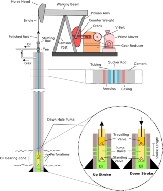
A pumpjack is the overground drive for a reciprocating piston pump in an oil well.

A hydraulic accumulator is a pressure storage reservoir in which an incompressible hydraulic fluid is held under pressure that is applied by an external source of mechanical energy. The external source can be an engine, a spring, a raised weight, or a compressed gas. An accumulator enables a hydraulic system to cope with extremes of demand using a less powerful pump, to respond more quickly to a temporary demand, and to smooth out pulsations. It is a type of energy storage device.

<span class="mw-page-title-main">Hydraulic machinery</span> Type of machine that uses liquid fluid power to perform work

Hydraulic machines use liquid fluid power to perform work. Heavy construction vehicles are a common example. In this type of machine, hydraulic fluid is pumped to various hydraulic motors and hydraulic cylinders throughout the machine and becomes pressurized according to the resistance present. The fluid is controlled directly or automatically by control valves and distributed through hoses, tubes, or pipes.

<span class="mw-page-title-main">Pneumatic cylinder</span> Mechanical device with compressed gas

Pneumatic cylinder, also known as air cylinder, is a mechanical device which uses the power of compressed gas to produce a force in a reciprocating linear motion.

<span class="mw-page-title-main">Axial piston pump</span>

An axial piston pump is a positive displacement pump that has a number of pistons in a circular array within a cylinder block.

A hydraulic seal is a relatively soft, non-metallic ring, captured in a groove or fixed in a combination of rings, forming a seal assembly, to block or separate fluid in reciprocating motion applications. Hydraulic seals are vital in machinery. Their use is critical in providing a way for fluid power to be converted to linear motion.

<span class="mw-page-title-main">Hydraulic motor</span> Machine converting flow into rotation

A hydraulic motor is a mechanical actuator that converts hydraulic pressure and flow into torque and angular displacement (rotation). The hydraulic motor is the rotary counterpart of the hydraulic cylinder as a linear actuator. Most broadly, the category of devices called hydraulic motors has sometimes included those that run on hydropower but in today's terminology the name usually refers more specifically to motors that use hydraulic fluid as part of closed hydraulic circuits in modern hydraulic machinery.

Artificial lift refers to the use of artificial means to increase the flow of liquids, such as crude oil or water, from a production well. Generally this is achieved by the use of a mechanical device inside the well or by decreasing the weight of the hydrostatic column by injecting gas into the liquid some distance down the well. A newer method called Continuous Belt Transportation (CBT) uses an oil absorbing belt to extract from marginal and idle wells. Artificial lift is needed in wells when there is insufficient pressure in the reservoir to lift the produced fluids to the surface, but often used in naturally flowing wells to increase the flow rate above what would flow naturally. The produced fluid can be oil, water or a mix of oil and water, typically mixed with some amount of gas.

<span class="mw-page-title-main">Valve actuator</span> Mechanism for opening and closing a valve

A valve actuator is the mechanism for opening and closing a valve. Manually operated valves require someone in attendance to adjust them using a direct or geared mechanism attached to the valve stem. Power-operated actuators, using gas pressure, hydraulic pressure or electricity, allow a valve to be adjusted remotely, or allow rapid operation of large valves. Power-operated valve actuators may be the final elements of an automatic control loop which automatically regulates some flow, level or other process. Actuators may be only to open and close the valve, or may allow intermediate positioning; some valve actuators include switches or other ways to remotely indicate the position of the valve.

<span class="mw-page-title-main">Hydraulic pump</span> Mechanical power source

A hydraulic pump is a mechanical source of power that converts mechanical power into hydraulic energy. Hydraulic pumps are used in hydraulic drive systems and can be hydrostatic or hydrodynamic. They generate flow with enough power to overcome pressure induced by a load at the pump outlet. When a hydraulic pump operates, it creates a vacuum at the pump inlet, which forces liquid from the reservoir into the inlet line to the pump and by mechanical action delivers this liquid to the pump outlet and forces it into the hydraulic system. Hydrostatic pumps are positive displacement pumps while hydrodynamic pumps can be fixed displacement pumps, in which the displacement cannot be adjusted, or variable displacement pumps, which have a more complicated construction that allows the displacement to be adjusted. Hydrodynamic pumps are more frequent in day-to-day life. Hydrostatic pumps of various types all work on the principle of Pascal's law.

<span class="mw-page-title-main">Plunger pump</span>

A plunger pump is a type of positive displacement pump where the high-pressure seal is stationary and a smooth cylindrical plunger slides through the seal. This makes them different from piston pumps and allows them to be used at higher pressures. This type of pump is often used to transfer municipal and industrial sewage.

<span class="mw-page-title-main">Pascal's law</span> Principle in fluid mechanics

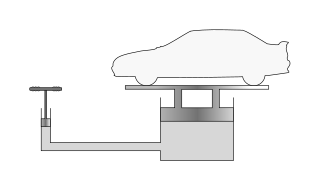
Pascal's law is a principle in fluid mechanics given by Blaise Pascal that states that a pressure change at any point in a confined incompressible fluid is transmitted throughout the fluid such that the same change occurs everywhere. The law was established by French mathematician Blaise Pascal in 1653 and published in 1663.

<span class="mw-page-title-main">Telescopic cylinder</span> Extending boom design

Telescopic cylinders are a special design of a hydraulic cylinder or pneumatic cylinder as well as pulley system which provide an exceptionally long output travel from a very compact retracted length. Typically the collapsed length of a telescopic cylinder is 20 to 40% of the fully extended length depending on the number of stages. Some pneumatic telescoping units are manufactured with retracted lengths of under 15% of overall extended unit length. This feature is very attractive to machine design engineers when a conventional single stage rod style actuator will not fit in an application to produce the required output stroke.

<span class="mw-page-title-main">Hydraulic intensifier</span>

A hydraulic intensifier is a hydraulic machine for transforming hydraulic power at low pressure into a reduced volume at higher pressure.

A pipe support or pipe hanger is a designed element that transfer the load from a pipe to the supporting structures. The load includes the weight of the pipe proper, the content that the pipe carries, all the pipe fittings attached to pipe, and the pipe covering such as insulation. The four main functions of a pipe support are to anchor, guide, absorb shock, and support a specified load. Pipe supports used in high or low temperature applications may contain insulation materials. The overall design configuration of a pipe support assembly is dependent on the loading and operating conditions.

<span class="mw-page-title-main">Single- and double-acting cylinders</span> Classification of reciprocating engine cylinders

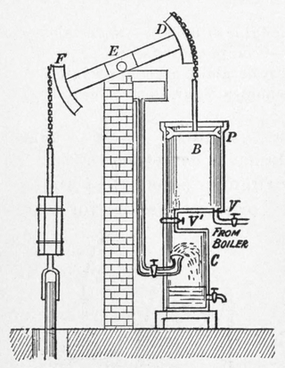
In mechanical engineering, the cylinders of reciprocating engines are often classified by whether they are single- or double-acting, depending on how the working fluid acts on the piston.

<span class="mw-page-title-main">Hydraulic jigger</span>

A hydraulic jigger is a hydraulically-powered mechanical winch.

References

  1. "Hydraulic Cylinder - an overview | ScienceDirect Topics". www.sciencedirect.com. Retrieved 2022-10-23.
  2. "What is a hydraulic cylinder? | Hydroline Blog - Experts of hydraulics". Hydroline . 5 June 2019.
  3. P.E, Charlie Young (2022-04-18). "Is Hydraulic Fluid Compressible?". EngineerExcel. Retrieved 2022-10-23.
  4. Management of Hazardous Energy: Deactivation, De-Energization, Isolation, and Lockout, Thomas Neil McManus, page 678, August 8, 2012, by CRC Press, Reference - 942 Pages - 273 B/W Illustrations, ISBN   9781439878361
  5. "Hydraulic Cylinders". Farm and Ranch Depot. Retrieved 2022-10-23.
  6. "HONED TUBES | SRB TUBES | HYDRAULIC CYLINDER TUBES", YOUNGLEE METAL, Sep 16, 2018.
  7. "Honing and Skiving&Burnishing Process for Manufacturing Cylinder Tubes", SKYLINE PIPES, Sep 6, 2018.
  8. "Hydraulic Cylinder: The 7 Basic Components You Need to Know - Kappa Engineering". kappaeng.co.za. 2020-09-21. Retrieved 2022-10-23.
  9. Component Parts of a Hydraulic Cylinder | https://www.crconline.com/catsearch/12/cylinder-components
  10. "Hydraulic Cylinders Archived 2017-09-07 at the Wayback Machine ", Metro Hydraulic, Retrieved June 6, 2016.
  11. 1 2 "Welded Cylinders vs. Tie Rod Cylinders Archived 2016-05-25 at the Wayback Machine ", Best Metal Products, Retrieved June 6, 2016.
  12. "Datong Group-What is the welded hydraulic cylinder". Datong Hydraulic (in Chinese (China)). Retrieved 2022-10-23.
  13. "Distribution of Forces on Cylinder Components | The Cylinde". Cylinder.co.uk. Retrieved 2018-10-03.
  14. Maximizing Cylinder Performance: A checklist of design guidelines ensures the best pneumatic cylinder for an application, Aug 20, 1998, Kenneth Korane, Machine Design magazine
  15. Fluid Power Design Handbook, Third Edition, page 112, By Frank Yeaple, CRC Press, 1995, 854 pages, ISBN   9780824795627
  16. 1 2 "Mounting Style Can Dramatically Improve Hydraulic and Pneumatic Cylinder Performance", Hydraulics & Pneumatics, Retrieved June 6, 2016
  17. "Hydraulic cylinders: Types, mounting methods, and key specifications". www.mobilehydraulictips.com.
  18. "What are Telescopic Cylinders, and How Do They Work?", Pneu-Hyd, Retrieved June 6, 2016.