Interference reflection microscopy

Last updated
Principle of interference reflection microscopy (IRM) showing interference effect on reflected waves and the result on the final image intensity. Dark purple wave represents the light from the light source. The light purple waves are the reflections from the cell membrane and from the glass surface. Upon hitting the glass surface, the reflected waves are shifted half a wavelength. When the membrane is very close to the glass, the reflected light will be reflected out of phase with the reflected beam from the glass. This will cause destructive interference (see red line), resulting in a dark pixel. If there is more distance between the membrane and the glass, the returning waves will be less shifted and will cause constructive interference (see red line), resulting in a brighter pixel in the final image. Indicated are the typical refractive indices of the glass, medium and the cell membrane, which determine the amount of reflection. IRM Interference Reflection Microscopy.svg
Principle of interference reflection microscopy (IRM) showing interference effect on reflected waves and the result on the final image intensity. Dark purple wave represents the light from the light source. The light purple waves are the reflections from the cell membrane and from the glass surface. Upon hitting the glass surface, the reflected waves are shifted half a wavelength. When the membrane is very close to the glass, the reflected light will be reflected out of phase with the reflected beam from the glass. This will cause destructive interference (see red line), resulting in a dark pixel. If there is more distance between the membrane and the glass, the returning waves will be less shifted and will cause constructive interference (see red line), resulting in a brighter pixel in the final image. Indicated are the typical refractive indices of the glass, medium and the cell membrane, which determine the amount of reflection.

Interference reflection microscopy (IRM), also called Reflection Interference Contrast Microscopy (RICM) or Reflection Contrast Microscopy (RCM) depending on the context, is an optical microscopy technique that leverages interference effects to form an image of an object on a glass surface. The intensity of the signal is a measure of proximity of the object to the glass surface. This technique can be used to study events at the cell membrane without the use of a (fluorescent) label as is the case for TIRF microscopy.

Contents

History and name

In 1964, Adam S. G. Curtis coined the term Interference Reflection Microscopy (IRM), using it in the field of cell biology to study embryonic chick heart fibroblasts. [1] [2] He used IRM to look at adhesion sites and distances of fibroblasts, noting that contact with the glass was mostly limited to the cell periphery and the pseudopodia. [1]

In 1975, Johan Sebastiaan Ploem introduced an improvement to IRM (published in a book chapter [3] ), which he called Reflection Contrast Microscopy (RCM). [4] The improvement is to use a so-called anti-flex objective and crossed polarizers to further reduce stray light in the optical system. Today, this scheme is mainly referred to as Reflection Interference Contrast Microscopy (RICM), [5] [6] the name of which was introduced by Bareiter-Hahn and Konrad Beck in 1979. [7]

However, the term IRM is sometimes to describe an RICM setup. The multiplicity of names used to describe the technique has caused some confusion, and was discussed as early as 1985 by Verschueren. [8]

Theory

To form an image of the attached cell, light of a specific wavelength is passed through a polarizer. This linear polarized light is reflected by a beam splitter towards the objective, which focuses the light on the specimen. The glass surface is reflective to a certain degree and will reflect the polarized light. Light that is not reflected by the glass will travel into the cell and be reflected by the cell membrane. Three situations can occur. First, when the membrane is close to the glass, the reflected light from the glass is shifted half of a wavelength, so that light reflected from the membrane will have a phase shift compared to the reflected light from the glass phases and therefore cancel each other out (interference). This interference results in a dark pixel in the final image (the left case in the figure). Second, when the membrane is not attached to the glass, the reflection from the membrane has a smaller phase shift compared to the reflected light from the glass, and therefore they will not cancel each other out, resulting in a bright pixel in the image (the right case in the figure). Third, when there is no specimen, only the reflected light from the glass is detected and will appear as bright pixels in the final image.

The reflected light will travel back to the beam splitter and pass through a second polarizer, which eliminates scattered light, before reaching the detector (usually a CCD camera) in order to form the final picture. The polarizers can increase the efficiency by reducing scattered light; however in a modern setup with a sensitive digital camera, they are not required. [9]

Theory

Reflection is caused by a change in the refraction index, so on every boundary a part of the light will be reflected. The amount of reflection is given by the reflection coefficient , according to the following rule: [8]

Reflectivity is a ratio of the reflected light intensity () and the incoming light intensity (): [8]

Using typical refractive indices for glass (1.50–1.54, see list), water (1.31, see list), the cell membrane (1.48) [10] and the cytosol (1.35), [10] one can calculate the fraction of light being reflected by each interface. The amount of reflection increases as the difference between refractive indices increases, resulting in a large reflection from the interface between the glass surface and the culture medium (about equal to water: 1.31–1.33). This means that without a cell the image will be bright, whereas when the cell is attached, the difference between medium and the membrane causes a large reflection that is slightly shifted in phase, causing interference with the light reflected by the glass. Because the amplitude of the light reflected from the medium-membrane interface is decreased due to scattering, the attached area will appear darker but not completely black. Because the cone of light focused on the sample gives rise to different angles of incident light, there is a broad range of interference patterns. When the patterns differ by less than 1 wavelength (the zero-order fringe), the patterns converge, resulting in increased intensity. This can be obtained by using an objective with a numerical aperture greater than 1. [8]

Requirements

In order to image cells using IRM, a microscope needs at least the following elements: 1) a light source, such as a halogen lamp, 2) an optical filter (which passes a small range of wavelengths), and 3) a beam splitter (which reflects 50% and transmits 50% of the chosen wavelength).

The light source needs to produce high intensity light, as a lot of light will be lost by the beam splitter and the sample itself. Different wavelengths result in different IRM images; Bereiter-Hahn and colleagues showed that for their PtK 2 cells, light with a wavelength of 546 nm resulted in better contrast than blue light with a wavelength of 436 nm. [7] There have been many refinements to the basic theory of IRM, most of which increase the efficiency and yield of the image formation. By placing polarizers and a quarter wave plate between the beam splitter and the specimen, the linear polarized light can be converted into circular polarized light and afterwards be converted back to linear polarized light, which increases the efficiency of the system. The circular polarizer article discusses this process in detail. Furthermore, by including a second polarizer, which is rotated 90° compared to the first polarizer, stray light can be prevented from reaching the detector, increasing the signal to noise ratio (see Figure 2 of Verschueren [8] ).

Biological applications

There are several ways IRM can be used to study biological samples. Early examples of uses of the technique focused on cell adhesion [1] and cell migration. [11]

Vesicle fusion

Two chromaffin cells imaged with DIC (left) and IRM (right). Chromaffin cell imaged with DIC and IRM.png
Two chromaffin cells imaged with DIC (left) and IRM (right).
Vesicle fusion visualized using IRM. Scale bar represents 2 μm.

More recently, the technique has been used to study exocytosis in chromaffin cells. [9] When imaged using DIC, chromaffin cells appear as round cells with small protrusions. When the same cell is imaged using IRM, the footprint of the cell on the glass can be clearly seen as a dark area with small protrusions. When vesicles fuse with the membrane, they appear as small light circles within the dark footprint (bright spots in the top cell in the right panel).

An example of vesicle fusion in chromaffin cells using IRM is shown in movie 1. Upon stimulation with 60  mM potassium, multiple bright spots begin to appear inside the dark footprint of the chromaffin cell as a result of exocytosis of dense core granules. Because IRM doesn't require a fluorescent label, it can be combined with other imaging techniques, such as epifluorescence and TIRF microscopy to study protein dynamics together with vesicle exocytosis and endocytosis. Another benefit of the lack of fluorescent labels is reduced phototoxicity.

Related Research Articles

<span class="mw-page-title-main">Microscopy</span> Viewing of objects which are too small to be seen with the naked eye

Microscopy is the technical field of using microscopes to view objects and areas of objects that cannot be seen with the naked eye. There are three well-known branches of microscopy: optical, electron, and scanning probe microscopy, along with the emerging field of X-ray microscopy.

<span class="mw-page-title-main">Refractive index</span> Ratio of the speed of light in vacuum to that in the medium

In optics, the refractive index of an optical medium is a dimensionless number that gives the indication of the light bending ability of that medium.

<span class="mw-page-title-main">Brewster's angle</span> Angle of incidence for which all reflected light will be polarized

Brewster's angle is an angle of incidence at which light with a particular polarization is perfectly transmitted through a transparent dielectric surface, with no reflection. When unpolarized light is incident at this angle, the light that is reflected from the surface is therefore perfectly polarized. This special angle of incidence is named after the Scottish physicist Sir David Brewster (1781–1868).

<span class="mw-page-title-main">Prism (optics)</span> Transparent optical element with flat, polished surfaces that refract light

An optical prism is a transparent optical element with flat, polished surfaces that are designed to refract light. At least one surface must be angled — elements with two parallel surfaces are not prisms. The most familiar type of optical prism is the triangular prism, which has a triangular base and rectangular sides. Not all optical prisms are geometric prisms, and not all geometric prisms would count as an optical prism. Prisms can be made from any material that is transparent to the wavelengths for which they are designed. Typical materials include glass, acrylic and fluorite.

<span class="mw-page-title-main">Mach–Zehnder interferometer</span> Device to determine relative phase shift

The Mach–Zehnder interferometer is a device used to determine the relative phase shift variations between two collimated beams derived by splitting light from a single source. The interferometer has been used, among other things, to measure phase shifts between the two beams caused by a sample or a change in length of one of the paths. The apparatus is named after the physicists Ludwig Mach and Ludwig Zehnder; Zehnder's proposal in an 1891 article was refined by Mach in an 1892 article. Demonstrations of Mach–Zehnder interferometry with particles other than photons had been demonstrated as well in multiple experiments.

<span class="mw-page-title-main">Michelson interferometer</span> Common configuration for optical interferometry

The Michelson interferometer is a common configuration for optical interferometry and was invented by the 19/20th-century American physicist Albert Abraham Michelson. Using a beam splitter, a light source is split into two arms. Each of those light beams is reflected back toward the beamsplitter which then combines their amplitudes using the superposition principle. The resulting interference pattern that is not directed back toward the source is typically directed to some type of photoelectric detector or camera. For different applications of the interferometer, the two light paths can be with different lengths or incorporate optical elements or even materials under test.

<span class="mw-page-title-main">Optical coating</span> Material which alters light reflection or transmission on optics

An optical coating is one or more thin layers of material deposited on an optical component such as a lens, prism or mirror, which alters the way in which the optic reflects and transmits light. These coatings have become a key technology in the field of optics. One type of optical coating is an anti-reflective coating, which reduces unwanted reflections from surfaces, and is commonly used on spectacle and camera lenses. Another type is the high-reflector coating, which can be used to produce mirrors that reflect greater than 99.99% of the light that falls on them. More complex optical coatings exhibit high reflection over some range of wavelengths, and anti-reflection over another range, allowing the production of dichroic thin-film filters.

<span class="mw-page-title-main">Optical filter</span> Filters which selectively transmit specific colors

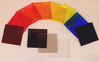
An optical filter is a device that selectively transmits light of different wavelengths, usually implemented as a glass plane or plastic device in the optical path, which are either dyed in the bulk or have interference coatings. The optical properties of filters are completely described by their frequency response, which specifies how the magnitude and phase of each frequency component of an incoming signal is modified by the filter.

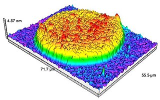
A total internal reflection fluorescence microscope (TIRFM) is a type of microscope with which a thin region of a specimen, usually less than 200 nanometers can be observed.

<span class="mw-page-title-main">Anti-reflective coating</span> Optical coating that reduces reflection

An antireflective, antiglare or anti-reflection (AR) coating is a type of optical coating applied to the surface of lenses, other optical elements, and photovoltaic cells to reduce reflection. In typical imaging systems, this improves the efficiency since less light is lost due to reflection. In complex systems such as cameras, binoculars, telescopes, and microscopes the reduction in reflections also improves the contrast of the image by elimination of stray light. This is especially important in planetary astronomy. In other applications, the primary benefit is the elimination of the reflection itself, such as a coating on eyeglass lenses that makes the eyes of the wearer more visible to others, or a coating to reduce the glint from a covert viewer's binoculars or telescopic sight.

<span class="mw-page-title-main">Distributed Bragg reflector</span> Structure used in waveguides

A distributed Bragg reflector (DBR) is a reflector used in waveguides, such as optical fibers. It is a structure formed from multiple layers of alternating materials with different refractive index, or by periodic variation of some characteristic of a dielectric waveguide, resulting in periodic variation in the effective refractive index in the guide. Each layer boundary causes a partial reflection and refraction of an optical wave. For waves whose vacuum wavelength is close to four times the optical thickness of the layers, the interaction between these beams generates constructive interference, and the layers act as a high-quality reflector. The range of wavelengths that are reflected is called the photonic stopband. Within this range of wavelengths, light is "forbidden" to propagate in the structure.

<span class="mw-page-title-main">Dark-field microscopy</span> Laboratory technique

Dark-field microscopy describes microscopy methods, in both light and electron microscopy, which exclude the unscattered beam from the image. Consequently, the field around the specimen is generally dark.

<span class="mw-page-title-main">Bright-field microscopy</span> Optical microscopy illumination technique

Bright-field microscopy (BF) is the simplest of all the optical microscopy illumination techniques. Sample illumination is transmitted white light, and contrast in the sample is caused by attenuation of the transmitted light in dense areas of the sample. Bright-field microscopy is the simplest of a range of techniques used for illumination of samples in light microscopes, and its simplicity makes it a popular technique. The typical appearance of a bright-field microscopy image is a dark sample on a bright background, hence the name.

Fluorescence interference contrast (FLIC) microscopy is a microscopic technique developed to achieve z-resolution on the nanometer scale.

Johan Sebastiaan Ploem is a Dutch microscopist and digital artist. He made significant contribution to the field of fluorescence microscopy, and invented reflection interference contrast microscopy.

<span class="mw-page-title-main">Erich Sackmann</span>

Erich Sackmann is a German experimental physicist and a pioneer of biophysics in Europe.

<span class="mw-page-title-main">Sarfus</span> Optical quantitative imaging technique

Sarfus is an optical quantitative imaging technique based on the association of:

<span class="mw-page-title-main">Thin-film interference</span> Optical phenomenon

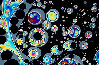
Thin-film interference is a natural phenomenon in which light waves reflected by the upper and lower boundaries of a thin film interfere with one another, increasing reflection at some wavelengths and decreasing it at others. When white light is incident on a thin film, this effect produces colorful reflections.

Photo-activated localization microscopy and stochastic optical reconstruction microscopy (STORM) are widefield fluorescence microscopy imaging methods that allow obtaining images with a resolution beyond the diffraction limit. The methods were proposed in 2006 in the wake of a general emergence of optical super-resolution microscopy methods, and were featured as Methods of the Year for 2008 by the Nature Methods journal. The development of PALM as a targeted biophysical imaging method was largely prompted by the discovery of new species and the engineering of mutants of fluorescent proteins displaying a controllable photochromism, such as photo-activatible GFP. However, the concomitant development of STORM, sharing the same fundamental principle, originally made use of paired cyanine dyes. One molecule of the pair, when excited near its absorption maximum, serves to reactivate the other molecule to the fluorescent state.

<span class="mw-page-title-main">Interferometric scattering microscopy</span>

Interferometric scattering microscopy (iSCAT) refers to a class of methods that detect and image a subwavelength object by interfering the light scattered by it with a reference light field. The underlying physics is shared by other conventional interferometric methods such as phase contrast or differential interference contrast, or reflection interference microscopy. The key feature of iSCAT is the detection of elastic scattering from subwavelength particles, also known as Rayleigh scattering, in addition to reflected or transmission signals from supra-wavelength objects. Typically, the challenge is the detection of tiny signals on top of large and complex, speckle-like backgrounds. iSCAT has been used to investigate nanoparticles such as viruses, proteins, lipid vesicles, DNA, exosomes, metal nanoparticles, semiconductor quantum dots, charge carriers and single organic molecules without the need for a fluorescent label.

References

  1. 1 2 3 Curtis AS (February 1964). "THE MECHANISM OF ADHESION OF CELLS TO GLASS : A Study by Interference Reflection Microscopy". The Journal of Cell Biology. 20 (2): 199–215. doi:10.1083/jcb.20.2.199. PMC   2106393 . PMID   14126869.
  2. Filler TJ, Peuker ET (April 2000). "Reflection contrast microscopy (RCM): a forgotten technique?". The Journal of Pathology. 190 (5): 635–8. doi:10.1002/(SICI)1096-9896(200004)190:5<635::AID-PATH571>3.0.CO;2-E. PMID   10727991. S2CID   43800311.
  3. Furth, Ralph van (1975). "Chapter 27: Reflection-contrast microscopy as a tool for investigation of the attachment of living cells to a glass surface". Mononuclear Phagocytes: In Immunity, Infection, and Pathology. Oxford: Blackwell Scientific. pp. 405–421. ISBN   0-632-00471-1. OCLC   2701405.
  4. Ploem, Johan Sebastiaan (2019-02-21). "Applications of reflection‐contrast microscopy, including the sensitive detection of the results ofin situhybridisation a review". Journal of Microscopy. Wiley. 274 (2): 79–86. doi:10.1111/jmi.12785. ISSN   0022-2720. PMID   30720204. S2CID   73431526.
  5. Theodoly, O.; Huang, Z.-H.; Valignat, M.-P. (2009-11-30). "New Modeling of Reflection Interference Contrast Microscopy Including Polarization and Numerical Aperture Effects: Application to Nanometric Distance Measurements and Object Profile Reconstruction" (PDF). Langmuir. American Chemical Society (ACS). 26 (3): 1940–1948. doi:10.1021/la902504y. ISSN   0743-7463. PMID   19947618.
  6. Limozin, Laurent; Sengupta, Kheya (2009-11-03). "Quantitative Reflection Interference Contrast Microscopy (RICM) in Soft Matter and Cell Adhesion". ChemPhysChem. Wiley. 10 (16): 2752–2768. doi:10.1002/cphc.200900601. ISSN   1439-4235.
  7. 1 2 Bereiter-Hahn J, Fox CH, Thorell B (September 1979). "Quantitative reflection contrast microscopy of living cells". The Journal of Cell Biology. 82 (3): 767–79. doi:10.1083/jcb.82.3.767. PMC   2110483 . PMID   389938.
  8. 1 2 3 4 5 Verschueren H (April 1985). "Interference reflection microscopy in cell biology: methodology and applications". Journal of Cell Science. 75 (1): 279–301. doi:10.1242/jcs.75.1.279. PMID   3900106.
  9. 1 2 Wu MM, Llobet A, Lagnado L (November 2009). "Loose coupling between calcium channels and sites of exocytosis in chromaffin cells". The Journal of Physiology. 587 (Pt 22): 5377–91. doi:10.1113/jphysiol.2009.176065. PMC   2793871 . PMID   19752110.
  10. 1 2 Dunn, Andrew Kenneth (1997). "Cell Structure". Light scattering properties of cells (PhD thesis). University of Texas at Austin. OCLC   39949488 . Retrieved February 23, 2010.
  11. Godwin SL, Fletcher M, Burchard RP (September 1989). "Interference reflection microscopic study of sites of association between gliding bacteria and glass substrata". Journal of Bacteriology. 171 (9): 4589–94. doi:10.1128/jb.171.9.4589-4594.1989. PMC   210255 . PMID   2768185.

Further reading