Level sensors detect the level of liquids and other fluids and fluidized solids, including slurries, granular materials, and powders that exhibit an upper free surface. Substances that flow become essentially horizontal in their containers (or other physical boundaries) because of gravity whereas most bulk solids pile at an angle of repose to a peak. The substance to be measured can be inside a container or can be in its natural form (e.g., a river or a lake). The level measurement can be either continuous or point values. Continuous level sensors measure level within a specified range and determine the exact amount of substance in a certain place, while point-level sensors only indicate whether the substance is above or below the sensing point. Generally the latter detect levels that are excessively high or low.
There are many physical and application variables that affect the selection of the optimal level monitoring method for industrial and commercial processes.[1] The selection criteria include the physical: phase (liquid, solid or slurry), temperature, pressure or vacuum, chemistry, dielectric constant of medium, density (specific gravity) of medium, agitation (action), acoustical or electrical noise, vibration, mechanical shock, tank or bin size and shape. Also important are the application constraints: price, accuracy, appearance, response rate, ease of calibration or programming, physical size and mounting of the instrument, monitoring or control of continuous or discrete (point) levels. In short, level sensors are one of the very important sensors and play very important role in a variety of consumer/ industrial applications. As with other types of sensors, level sensors are available or can be designed using a variety of sensing principles. Selection of an appropriate type of sensor suiting to the application requirement is very important.
Point and continuous level detection for solids
A variety of sensors are available for point level detection of solids. These include vibrating, rotating paddle, mechanical (diaphragm), microwave (radar), capacitance, optical, pulsed-ultrasonic and ultrasonic level sensors.
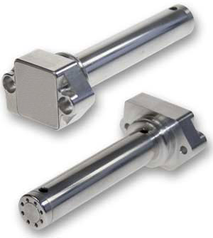
Vibrating point
Principle of vibration point probe
These detect levels of very fine powders (bulk density: 0.02–0.2g/cm3), fine powders (bulk density: 0.2–0.5g/cm3), and granular solids (bulk density: 0.5g/cm3 or greater). With proper selection of vibration frequency and suitable sensitivity adjustments, they can also sense the level of highly fluidized powders and electrostatic materials.
Single-probe vibrating level sensors are ideal for bulk powder level. Since only one sensing element contacts the powder, bridging between two probe elements is eliminated and media build-up is minimized. The vibration of the probe tends to eliminate build-up of material on the probe element. Vibrating level sensors are not affected by dust, static charge build-up from dielectric powders, or changes in conductivity, temperature, pressure, humidity or moisture content. Tuning-fork style vibration sensors are another alternative. They tend to be less costly, but are prone to material buildup between the tines,
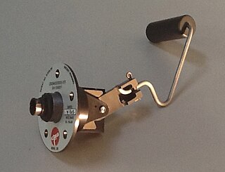
Rotating paddle
Rotating paddle level sensors are a very old and established technique for bulk solid point level indication. The technique uses a low-speed gear motor that rotates a paddle wheel. When the paddle is stalled by solid materials, the motor is rotated on its shaft by its own torque until a flange mounted on the motor contacts a mechanical switch. The paddle can be constructed from a variety of materials, but tacky material must not be allowed to build up on the paddle. Build-up may occur if the process material becomes tacky because of high moisture levels or high ambient humidity in the hopper. For materials with very low weight per unit volume such as Perlite, Bentonite or fly ash, special paddle designs and low-torque motors are used. Fine particles or dust must be prevented from penetrating the shaft bearings and motor by proper placement of the paddle in the hopper or bin and using appropriate seals.
Admittance-type
An RF admittance level sensor uses a rod probe and RF source to measure the change in admittance. The probe is driven through a shielded coaxial cable to eliminate the effects of changing cable capacitance to ground. When the level changes around the probe, a corresponding change in the dielectric is observed. This changes the admittance of this imperfect capacitor and this change is measured to detect change of level.[2]
Point level detection of liquids
Typical systems for point level detection in liquids include magnetic and mechanical floats, pressure sensors, electroconductive sensing or electrostatic (capacitance or inductance) detectors—and by measurement of a signal's time-of-flight to the fluid surface, through electromagnetic (such as magnetostrictive), ultrasonic, radar or optical sensors.[3][4]
The principle behind magnetic, mechanical, cable, and other float level sensors often involves the opening or closing of a mechanical switch, either through direct contact with the switch, or magnetic operation of a reed. In other instances, such as magnetostrictive sensors, continuous monitoring is possible using a float principle.
With magnetically actuated float sensors, switching occurs when a permanent magnet sealed inside a float rises or falls to the actuation level. With a mechanically actuated float, switching occurs as a result of the movement of a float against a miniature (micro) switch. For both magnetic and mechanical float level sensors, chemical compatibility, temperature, specific gravity (density), buoyancy, and viscosity affect the selection of the stem and the float. For example, larger floats may be used with liquids with specific gravities as low as 0.5 while still maintaining buoyancy. The choice of float material is also influenced by temperature-induced changes in specific gravity and viscosity – changes that directly affect buoyancy.[5]
Float-type sensors can be designed so that a shield protects the float itself from turbulence and wave motion. Float sensors operate well in a wide variety of liquids, including corrosives. When used for organic solvents, however, one will need to verify that these liquids are chemically compatible with the materials used to construct the sensor. Float-style sensors should not be used with high viscosity (thick) liquids, sludge or liquids that adhere to the stem or floats, or materials that contain contaminants such as metal chips; other sensing technologies are better suited for these applications.
A special application of float-type sensors is the determination of interface level in oil-water separation systems. Two floats can be used with each float sized to match the specific gravity of the oil on one hand, and the water on the other. Another special application of a stem type float switch is the installation of temperature or pressure sensors to create a multi-parameter sensor. Magnetic float switches are popular for simplicity, dependability and low cost.
A variation of magnetic sensing is the "Hall effect" sensor which utilizes the magnetic sensing of a mechanical gauge's indications. In a typical application, a magnetism-sensitive "Hall effect sensor" is affixed to a mechanical tank gauge that has a magnetized indicator needle, so as to detect the indicating position of the gauge's needle. The magnetic sensor translates the indicator needle position into an electrical signal, allowing other (usually remote) indication or signalling.[3]
Pneumatic
Pneumatic level sensors are used where hazardous conditions exist, where there is no electric power or its use is restricted, or in applications involving heavy sludge or slurry. As the compression of a column of air against a diaphragm is used to actuate a switch, no process liquid contacts the sensor's moving parts. These sensors are suitable for use with highly viscous liquids such as grease, as well as water-based and corrosive liquids. This has the additional benefit of being a relatively low cost technique for point level monitoring. A variation of this technique is the "bubbler", which compresses air into a tube to the bottom of the tank, until the pressure increase halts as the air pressure gets high enough to expel air bubbles from the bottom of the tube, overcoming the pressure there. The measurement of the stabilized air pressure indicates the pressure at the bottom of the tank, and, hence, the mass of fluid above.[6][7][8][9][3][4]
Conductive
Conductive level sensors are ideal for the point level detection of a wide range of conductive liquids such as water, and is especially well suited for highly corrosive liquids such as caustic soda, hydrochloric acid, nitric acid, ferric chloride, and similar liquids. For those conductive liquids that are corrosive, the sensor's electrodes need to be constructed from titanium, Hastelloy B or C, or 316 stainless steel and insulated with spacers, separators or holders of ceramic, polyethylene and Teflon-based materials. Depending on their design, multiple electrodes of differing lengths can be used with one holder. Since corrosive liquids become more aggressive as temperature and pressure increase, these extreme conditions need to be considered when specifying these sensors.
Conductive level sensors use a low-voltage, current-limited power source applied across separate electrodes. The power supply is matched to the conductivity of the liquid, with higher voltage versions designed to operate in less conductive (higher resistance) mediums. The power source frequently incorporates some aspect of control, such as high-low or alternating pump control. A conductive liquid contacting both the longest probe (common) and a shorter probe (return) completes a conductive circuit. Conductive sensors are extremely safe because they use low voltages and currents. Since the current and voltage used is inherently small, for personal safety reasons, the technique is also capable of being made intrinsically safe to meet international standards for hazardous locations. Conductive probes have the additional benefit of being solid-state devices and are very simple to install and use. In some liquids and applications, maintenance can be an issue. The probe must continue to be conductive. If buildup insulates the probe from the medium, it will stop working properly. A simple inspection of the probe will require an ohmmeter connected across the suspect probe and the ground reference.
Typically, in most water and wastewater wells, the well itself with its ladders, pumps and other metal installations, provides a ground return. However, in chemical tanks, and other non-grounded wells, the installer must supply a ground return, typically an earth rod.
State dependent frequency monitor
A microprocessor controlled frequency state change detection method uses a low amplitude signal generated on multiple sensor probes of differing lengths. Each probe has a frequency separate from all other probes in the array and independently changes state when touched by water. The state change of the frequency on each probe is monitored by a microprocessor which can perform multiple water level control functions.
A strength of state dependent frequency monitoring is long term stability of the sensing probes. The signal strength is not sufficient to cause fouling, degradation, or deterioration of the sensors due to electrolysis in contaminated water. Sensor cleaning requirements are minimal or eliminated. Use of multiple sensing rods of different length allows the user to intuitively set up control switches at various water heights.
The microprocessor in a state dependent frequency monitor can actuate valves and/or large pumps with very low power consumption. Multiple switch controls can be built in to small package while providing complex, application specific functionality using the microprocessor. Low power consumption of the controls is consistent across large and small field applications. This universal technology is used in applications with wide-ranging liquid quality.
Sensors for both point level detection and continuous monitoring
Ultrasonic
Ultrasonic level sensor used in a water treatment plant
Ultrasonic level sensors are used for non-contact level sensing of highly viscous liquids, as well as bulk solids. They are also widely used in water treatment applications for pump control and open channel flow measurement. The sensors emit high frequency (20kHz to 200kHz) acoustic waves that are reflected back to and detected by the emitting transducer.[3]
Ultrasonic level sensors are also affected by the changing speed of sound due to moisture, temperature, and pressures. Correction factors can be applied to the level measurement to improve the accuracy of measurement.
Turbulence, foam, steam, chemical mists (vapors), and changes in the concentration of the process material also affect the ultrasonic sensor's response. Turbulence and foam prevent the sound wave from being properly reflected to the sensor; steam and chemical mists and vapors distort or absorb the sound wave; and variations in concentration cause changes in the amount of energy in the sound wave that is reflected back to the sensor. Stilling wells and waveguides are used to prevent errors caused by these factors.
Proper mounting of the transducer is required to ensure the best response to reflected sound. In addition, the hopper, bin, or tank should be relatively free of obstacles such as weldments, brackets, or ladders to minimise false returns and the resulting erroneous response, although most modern systems have sufficiently "intelligent" echo processing to make engineering changes largely unnecessary except where an intrusion blocks the line of sight of the transducer to the target. Since the ultrasonic transducer is used both for transmitting and receiving the acoustic energy, it is subject to a period of mechanical vibration known as "ringing". This vibration must attenuate (stop) before the echoed signal can be processed. The net result is a distance from the face of the transducer that is blind and cannot detect an object. It is known as the "blanking zone", typically 150mm to 1m, depending on the range of the transducer.
The requirement for electronic signal processing circuitry can be used to make the ultrasonic sensor an intelligent device. Ultrasonic sensors can be designed to provide point level control, continuous monitoring or both. Due to the presence of a microprocessor and relatively low power consumption, there is also the capability for serial communication from to other computing devices making this a good technique for adjusting calibration and filtering of the sensor signal, remote wireless monitoring or plant network communications. The ultrasonic sensor enjoys wide popularity due to the powerful mix of low price and high functionality.
Capacitance
Capacitance level sensors excel in sensing the presence of a wide variety of solids, aqueous and organic liquids, and slurries.[10] The technique is frequently referred to as RF for the radio frequency signals applied to the capacitance circuit. The sensors can be designed to sense material with dielectric constants as low as 1.1 (coke and fly ash) and as high as 88 (water) or more. Sludges and slurries such as dehydrated cake and sewage slurry (dielectric constant approx. 50) and liquid chemicals such as quicklime (dielectric constant approx. 90) can also be sensed.[3] Dual-probe capacitance level sensors can also be used to sense the interface between two immiscible liquids with substantially different dielectric constants, providing a solid state alternative to the aforementioned magnetic float switch for the "oil-water interface" application.
Since capacitance level sensors are electronic devices, phase modulation and the use of higher frequencies makes the sensor suitable for applications in which dielectric constants are similar. The sensor contains no moving parts, is rugged, simple to use, and easy to clean, and can be designed for high temperature and pressure applications. A danger exists from build-up and discharge of a high-voltage static charge that results from the rubbing and movement of low dielectric materials, but this danger can be eliminated with proper design and grounding.
Appropriate choice of probe materials reduces or eliminates problems caused by abrasion and corrosion. Point level sensing of adhesives and high-viscosity materials such as oil and grease can result in the build-up of material on the probe; however, this can be minimized by using a self-tuning sensor. For liquids prone to foaming and applications prone to splashing or turbulence, capacitance level sensors can be designed with splashguards or stilling wells, among other devices.
A significant limitation for capacitance probes is in tall bins used for storing bulk solids. The requirement for a conductive probe that extends to the bottom of the measured range is problematic. Long conductive cable probes (20 to 50 meters long), suspended into the bin or silo, are subject to tremendous mechanical tension due to the weight of the bulk powder in the silo and the friction applied to the cable. Such installations will frequently result in a cable breakage.
Optical interface
Optical sensors are used for point level sensing of sediments, liquids with suspended solids, and liquid-liquid interfaces. These sensors sense the decrease or change in transmission of infrared light emitted from an infrared diode (LED). With the proper choice of construction materials and mounting location, these sensors can be used with aqueous, organic, and corrosive liquids.
A common application of economical infrared-based optical interface point level sensors is detecting the sludge/water interface in settling ponds. By using pulse modulation techniques and a high power infrared diode, one can eliminate interference from ambient light, operate the LED at a higher gain, and lessen the effects of build-up on the probe.
An alternate approach for continuous optical level sensing involves the use of a laser. Laser light is more concentrated and therefore is more capable of penetrating dusty or steamy environments. Laser light will reflect off most solid, liquid surfaces. The time of flight can be measured with precise timing circuitry, to determine the range or distance of the surface from the sensor. Lasers remain limited in use in industrial applications due to cost, and concern for maintenance. The optics must be frequently cleaned to maintain performance.
Microwave
Microwave sensors are ideal for use in moist, vaporous, and dusty environments as well as in applications in which temperatures and pressures vary. Microwaves (also frequently described as radar), will penetrate temperature and vapor layers that may cause problems for other techniques, such as ultrasonic.[3] Microwaves are electromagnetic energy and therefore do not require air molecules to transmit the energy making them useful in vacuums. Microwaves, as electromagnetic energy, are reflected by objects with high conductive properties, like metal and conductive water. Alternately, they are absorbed in various degrees by 'low dielectric' or insulating mediums such as plastics, glass, paper, many powders and food stuffs and other solids.
Microwave sensors are executed in a wide variety of techniques. Two basic signal processing techniques are applied, each offering its own advantages: pulsed or time-domain reflectometry (TDR) which is a measurement of time of flight divided by the speed of electromagnetic waves in the medium (speed of light divided by the square root of the dielectric constant of the medium [11]), similar to ultrasonic level sensors, and Doppler systems employing FMCW techniques. Just as with ultrasonic level sensors, microwave sensors are executed at various frequencies, from 1GHz to 60GHz.[12] Generally, the higher the frequency, the more accurate, and the more costly. Microwave is executed non-contact technique or guided. The first is done by monitoring a microwave signal that is transmitted through free space (including vacuum) and reflected back, or can be executed as a "radar on a wire" technique, generally known as guided wave radar or guided microwave radar. In the latter technique, performance generally improves in powders and low dielectric media that are not good reflectors of electromagnetic energy transmitted through a void (as in non-contact microwave sensors). This technique can use application specific waveguides to get more accurate results or additional information required for sensor application (e.g. some sensors can use tank parts or other equipment as a waveguide or its part).[13] It's common practice to use remote waveguides, when waveguide is distanced from electronic part (commonly for reservoirs with harsh conditions, radiation, or boiling under high pressure liquids/gases, etc.). But with the guided technique the same mechanical constraints exist that cause problems for the capacitance (RF) techniques mentioned previously by having a probe in the vessel.
Non contact microwave-based radar sensors are able to see through low conductivity 'microwave-transparent' (non-conductive) glass/plastic windows or vessel walls through which the microwave beam can be passed and measure a 'microwave reflective' (conductive) liquid inside (in the same way as to use a plastic bowl in a microwave oven). They are also largely unaffected by high temperature, pressure, vacuum or vibration. As these sensors do not require physical contact with the process material, so the transmitter /receiver can be mounted a safe distance above/from the process, even with an antenna extension of several meters to reduce temperature, yet still respond to the changes in level or distance changes e.g. they are ideal for measurement of molten metal products at over 1200°C. Microwave transmitters also offer the same key advantage of ultrasonics: the presence of a microprocessor to process the signal, provide numerous monitoring, controls, communications, setup and diagnostic capabilities and are independent of changing density, viscosity and electrical properties. Additionally, they solve some of the application limitations of ultrasonics: operation in high pressure and vacuum, high temperatures, dust, temperature and vapor layers. Guided wave radars can measure in narrow confined spaces very successfully, as the guide element ensures correct transmission to and from the measured liquid. Applications such as inside stilling tubes or external bridles or cages, offer an excellent alternative to float or displacement devices, as they remove any moving parts or linkages and are unaffected by density changes or build up. They are also excellent with very low microwave reflectivity products like liquid gasses (LNG, LPG, ammonia) which are stored at low temperatures/high pressures, although care needs to be taken on sealing arrangements and hazardous area approvals. On bulk solids and powders, GWR offers a great alternative to radar or ultrasonic sensors, but some care needs to be taken over cable wear and roof loading by the product movement.
One perceived major disadvantage of microwave or radar techniques for level monitoring is the relatively high price of such sensors and complex set up. However, price has reduced significantly over the last few years, to match those of longer range ultrasonics, with simplified set up of both techniques also improving ease of use.
Continuous level measurement of liquids
Magnetostrictive
Magnetostrictive level sensors are similar to float type sensors in that a permanent magnet sealed inside a float travels up and down a stem in which a magnetostrictive wire is sealed. Ideal for high-accuracy, continuous level measurement of a wide variety of liquids in storage and shipping containers, these sensors require the proper choice of float based on the specific gravity of the liquid. When choosing float and stem materials for magnetostrictive level sensors, the same guidelines described for magnetic and mechanical float level sensors apply.
Magnetostrictive level and position devices charge the magnetostrictive wire with electric current, when the field intersects the floats' magnetic field a mechanical twist or pulse is generated, this travels back down the wire at the speed of sound, like ultrasound or radar the distance is measured by time of flight from pulse to return pulse registry. the time of flight corresponds to the distance from the sensor detecting the return pulse.
Because of the accuracy possible with the magnetostrictive technique, it is popular for "custody-transfer" applications. It can be permitted by an agency of weights and measures for conducting commercial transactions. It is also frequently applied on magnetic sight gages. In this variation, the magnet is installed in a float that travels inside a gage glass or tube. The magnet operates on the sensor which is mounted externally on the gage. Boilers and other high temperature or pressure applications take advantage of this performance quality
Resistive chain
Resistive chain level sensors are similar to magnetic float level sensors in that a permanent magnet sealed inside a float moves up and down a stem in which closely spaced switches and resistors are sealed. When the switches are closed, the resistance is summed and converted to current or voltage signals that are proportional to the level of the liquid.
The choice of float and stem materials depends on the liquid in terms of chemical compatibility as well as specific gravity and other factors that affect buoyancy. These sensors work well for liquid level measurements in marine, chemical processing, pharmaceuticals, food processing, waste treatment, and other applications. With the proper choice of two floats, resistive chain level sensors can also be used to monitor for the presence of an interface between two immiscible liquids whose specific gravities are more than 0.6, but differ by as little as 0.1 unit.
Magnetoresistive
Magnetoresistive level sensor
Magnetoresistance float level sensors are similar to float level sensors however a permanent magnet pair is sealed inside the float arm pivot. As the float moves up the motion and location are transmitted as the angular position of the magnetic field. This detection system is highly accurate down to 0.02° of motion. The field compass location provides a physical location of the float position. The choice of float and stem materials depends on the liquid in terms of chemical compatibility as well as specific gravity and other factors that affect buoyancy of the float. The electronic monitoring system does not come in contact with the fluid and is considered intrinsically safe or explosion proof. These sensors work well for liquid level measurements in marine, vehicle, aviation, chemical processing, pharmaceuticals, food processing, waste treatment, and other applications.
Due to the presence of a microprocessor and low power consumption, there is also capability for serial communication from to other computing devices making this a good technique for adjusting calibration and filtering of the sensor signal.
Hydrostatic pressure level sensors are submersible or externally mounted pressure sensors suitable for measuring the level of corrosive liquids in deep tanks or water in reservoirs. Typically, fluid level is determined by the pressure at the bottom of the fluid containment (tank or reservoir); the pressure at the bottom, adjusted for the density / specific gravity of the fluid, indicates the depth of the fluid.[3] For these sensors, using chemically compatible materials is important to assure proper performance. Sensors are commercially available from 10mbar to 1000bar.
Since these sensors sense increasing pressure with depth and because the specific gravities of liquids are different, the sensor must be properly calibrated for each application. In addition, large variations in temperature cause changes in specific gravity that should be accounted for when the pressure is converted to level. These sensors can be designed to keep the diaphragm free of contamination or build-up, thus ensuring proper operation and accurate hydrostatic pressure level measurements.
For use in open air applications, where the sensor cannot be mounted to the bottom of the tank or pipe thereof, a special version of the hydrostatic pressure level sensor, a level probe, can be suspended from a cable into the tank to the bottom point that is to be measured.[3] The sensor must be specially designed to seal the electronics from the liquid environment. In tanks with a small head pressure (less than 100 INWC), it is very important to vent the back of the sensor gauge to atmospheric pressure. Otherwise, normal changes in barometric pressure will introduce large error in the sensor output signal. In addition, most sensors need to be compensated for temperature changes in the fluid.
Operation
Pressure level probes are submerged directly into the liquid and remain permanently floating above the tank bottom. The measurement is carried out according to the hydrostatic principle. The gravity pressure of the liquid column causes an expansion of the pressure-sensitive sensor element, which converts the measured pressure into an electrical standard signal. The connecting cable of level probes has several tasks to fulfil. In addition to the power supply and signal forwarding, the level sensor is held in place by the cable. The cable also includes a thin air tube that directs the ambient air pressure to the level probe. Level probes are therefore usually designed as relative pressure sensors, which use the current ambient pressure as the zero point of their measuring range.
Without this so-called relative pressure compensation, level probes would not only measure the hydrostatic pressure but also the air pressure on the liquid column. At sea level, this is about 1013 mbar - which would correspond to the pressure exerted by a water column ten meters high. In addition, a variable air pressure would affect the measurement result. Typical air pressure fluctuations of about +/- 20 mbar, corresponding to +/- 20 cmWs (water column).
For deep well designs, the Sealed Gauge measuring principle is also used. From a depth of approx. 20 m, the relative pressure can only be compensated to a limited extent by the thin hose. The level sensor is then designed as an absolute pressure transmitter whose zero point is adjusted to the desired mean air pressure depending on the location of use. This means that the level sensor no longer has any connection to the atmosphere. Possible fluctuations in air pressure may have an impact on the measurement result, but they play a rather minor role in deep well wells.
Formulation
Hydrostatic pressure, also gravity pressure or gravity pressure, occurs within a stationary fluid. It is caused by gravity and depends on the density and height of the liquid column. The mass of the fluid does not matter - see also hydrostatic paradox - i. e. not the total weight of the liquid in the container, but the filling level is decisive.
The measuring minimum level starts from a complete covering of the measuring element near the head end of the level sensor. Filling levels below the level probe are not detected. Depending on the application and mounting height, it is therefore necessary to adjust the level in the evaluation unit to the respective mounting height with an offset setting.
Design types
Depending on the requirements of the site, level probes offer different features:
An air bubbler level sensor uses a tube with an opening below the surface of the liquid level. A fixed flow of air is passed through the tube. Pressure in the tube is proportional to the depth (and density) of the liquid over the outlet of the tube.[3]
Air bubbler systems contain no moving parts, making them suitable for measuring the level of sewage, drainage water, sewage sludge, night soil, or water with large quantities of suspended solids. The only part of the sensor that contacts the liquid is a bubble tube which is chemically compatible with the material whose level is to be measured. Since the point of measurement has no electrical components, the technique is a good choice for classified hazardous areas. The control portion of the system can be located safely away, with the pneumatic plumbing isolating the hazardous from the safe area.
Air bubbler systems are a good choice for open tanks at atmospheric pressure and can be built so that high-pressure air is routed through a bypass valve to dislodge solids that may clog the bubble tube. The technique is inherently self-cleaning. It is highly recommended for liquid level measurement applications where ultrasonic, float or microwave techniques have proved undependable. The system will require constant supply of air during measurement. The end of the tube should be above certain height to avoid sludge from clogging the tube.
Gamma ray
A nuclear level gauge or gamma ray gauge measures level by the attenuation of gamma rays passing through a process vessel.[14] The technique is used to regulate the level of molten steel in a continuous casting process of steelmaking. The water-cooled mold is arranged with a source of radiation, such as cobalt-60 or caesium-137, on one side and a sensitive detector such as a scintillation counter on the other. As the level of molten steel rises in the mold, less of the gamma radiation is detected by the sensor. The technique allows non-contact measurement where the heat of the molten metal makes contact techniques and even many non-contact techniques impractical.
Nucleonic level sensors are often used in mineral crushing circuits, where an increase in gamma ray detection indicates a void, compared to being filled with ore.[15]
Pressure measurement is the measurement of an applied force by a fluid on a surface. Pressure is typically measured in units of force per unit of surface area. Many techniques have been developed for the measurement of pressure and vacuum. Instruments used to measure and display pressure mechanically are called pressure gauges,vacuum gauges or compound gauges. The widely used Bourdon gauge is a mechanical device, which both measures and indicates and is probably the best known type of gauge.
Relative density, also called specific gravity, is a dimensionless quantity defined as the ratio of the density of a substance to the density of a given reference material. Specific gravity for liquids is nearly always measured with respect to water at its densest ; for gases, the reference is air at room temperature. The term "relative density" is preferred in SI, whereas the term "specific gravity" is gradually being abandoned.
Flow measurement is the quantification of bulk fluid movement. Flow can be measured using devices called flowmeters in various ways. The common types of flowmeters with industrial applications are listed below:
This information can then be used to measure velocity or path length, or as a way to learn about the particle or medium's properties. The traveling object may be detected directly or indirectly. Time of flight technology has found valuable applications in the monitoring and characterization of material and biomaterials, hydrogels included.
A surface acoustic wave (SAW) is an acoustic wave traveling along the surface of a material exhibiting elasticity, with an amplitude that typically decays exponentially with depth into the material, such that they are confined to a depth of about one wavelength.
In electrical engineering, partial discharge (PD) is a localized dielectric breakdown (DB) of a small portion of a solid or fluid electrical insulation (EI) system under high voltage (HV) stress. While a corona discharge (CD) is usually revealed by a relatively steady glow or brush discharge (BD) in air, partial discharges within solid insulation system are not visible.
Microwave spectroscopy is the spectroscopy method that employs microwaves, i.e. electromagnetic radiation at GHz frequencies, for the study of matter.
Dielectric heating, also known as electronic heating, radio frequency heating, and high-frequency heating, is the process in which a radio frequency (RF) alternating electric field, or radio wave or microwave electromagnetic radiation heats a dielectric material. At higher frequencies, this heating is caused by molecular dipole rotation within the dielectric.
In electrical engineering, a capacitor is a device that stores electrical energy by accumulating electric charges on two closely spaced surfaces that are insulated from each other. The capacitor was originally known as the condenser, a term still encountered in a few compound names, such as the condenser microphone. It is a passive electronic component with two terminals.
Ultrasonic transducers and ultrasonic sensors are devices that generate or sense ultrasound energy. They can be divided into three broad categories: transmitters, receivers and transceivers. Transmitters convert electrical signals into ultrasound, receivers convert ultrasound into electrical signals, and transceivers can both transmit and receive ultrasound.
Electromagnetic acoustic transducer (EMAT) is a transducer for non-contact acoustic wave generation and reception in conducting materials. Its effect is based on electromagnetic mechanisms, which do not need direct coupling with the surface of the material. Due to this couplant-free feature, EMATs are particularly useful in harsh, i.e., hot, cold, clean, or dry environments. EMATs are suitable to generate all kinds of waves in metallic and/or magnetostrictive materials. Depending on the design and orientation of coils and magnets, shear horizontal (SH) bulk wave mode, surface wave, plate waves such as SH and Lamb waves, and all sorts of other bulk and guided-wave modes can be excited. After decades of research and development, EMAT has found its applications in many industries such as primary metal manufacturing and processing, automotive, railroad, pipeline, boiler and pressure vessel industries, in which they are typically used for nondestructive testing (NDT) of metallic structures.
Capacitance sensors use capacitance to measure the dielectric permittivity of a surrounding medium. The configuration is like the neutron probe where an access tube made of PVC is installed in the soil; probes can also be modular (comb-like) and connected to a logger. The sensing head consists of an oscillator circuit, the frequency is determined by an annular electrode, fringe-effect capacitor, and the dielectric constant of the soil. Each capacitor sensor consists of two metal rings mounted on the circuit board at some distance from the top of the access tube. These rings are a pair of electrodes, which form the plates of the capacitor with the soil acting as the dielectric in between. The plates are connected to an oscillator, consisting of an inductor and a capacitor. The oscillating electrical field is generated between the two rings and extends into the soil medium through the wall of the access tube. The capacitor and the oscillator form a circuit, and changes in dielectric constant of surrounding media are detected by changes in the operating frequency. The capacitance sensors are designed to oscillate in excess of 100 MHz inside the access tube in free air. The output of the sensor is the frequency response of the soil’s capacitance due to its soil moisture level.
In electrical engineering, capacitive sensing is a technology, based on capacitive coupling, that can detect and measure anything that is conductive or has a dielectric constant different from air. Many types of sensors use capacitive sensing, including sensors to detect and measure proximity, pressure, position and displacement, force, humidity, fluid level, and acceleration. Human interface devices based on capacitive sensing, such as touchpads, can replace the computer mouse. Digital audio players, mobile phones, and tablet computers will sometimes use capacitive sensing touchscreens as input devices. Capacitive sensors can also replace mechanical buttons.
Capacitive displacement sensors are "non-contact devices capable of high-resolution measurement of the position and/or change of position of any conductive target". They are also able to measure the thickness or density of non-conductive materials. Capacitive displacement sensors are used in a wide variety of applications including semiconductor processing, assembly of precision equipment such as disk drives, precision thickness measurements, machine tool metrology and assembly line testing. These types of sensors can be found in machining and manufacturing facilities around the world.
Liquid level floats, also known as float balls, are spherical, cylindrical, oblong or similarly shaped objects, made from either rigid or flexible material, that are buoyant in water and other liquids. They are non-electrical hardware frequently used as visual sight-indicators for surface demarcation and level measurement. They may also be incorporated into switch mechanisms or translucent fluid-tubes as a component in monitoring or controlling liquid level.
Fiber-optical thermometers can be used in electromagnetically strongly influenced environment, in microwave fields, power plants or explosion-proof areas and wherever measurement with electrical temperature sensors are not possible.
A density meter (densimeter) is a device which measures the density of an object or material. Density is usually abbreviated as either or . Typically, density either has the units of or . The most basic principle of how density is calculated is by the formula:
Three-dimensional electrical capacitance tomography also known as electrical capacitance volume tomography (ECVT) is a non-invasive 3D imaging technology applied primarily to multiphase flows. Was introduced in the early 2000s as an extension of the conventional two-dimensional ECT. In conventional electrical capacitance tomography, sensor plates are distributed around a surface of interest. Measured capacitance between plate combinations is used to reconstruct 2D images (tomograms) of material distribution. Because the ECT sensor plates are required to have lengths on the order of the domain cross-section, 2D ECT does not provide the required resolution in the axial dimension. In ECT, the fringing field from the edges of the plates is viewed as a source of distortion to the final reconstructed image and is thus mitigated by guard electrodes. 3D ECT exploits this fringing field and expands it through 3D sensor designs that deliberately establish an electric field variation in all three dimensions. In 3D tomography, the data are acquired in 3D geometry, and the reconstruction algorithm produces the three-dimensional image directly, in contrast to 2D tomography, where 3D information might be obtained by stacking 2D slices reconstructed individually.
References
↑ EngineersGarage (18 September 2012). "Level Sensors". www.engineersgarage.com. Archived from the original on 2012-09-20. Retrieved 2018-09-16.
This page is based on this Wikipedia article Text is available under the CC BY-SA 4.0 license; additional terms may apply. Images, videos and audio are available under their respective licenses.