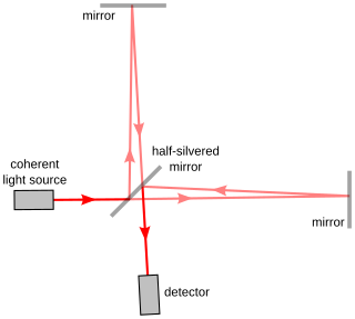
Interferometry is a technique which uses the interference of superimposed waves to extract information. Interferometry typically uses electromagnetic waves and is an important investigative technique in the fields of astronomy, fiber optics, engineering metrology, optical metrology, oceanography, seismology, spectroscopy, quantum mechanics, nuclear and particle physics, plasma physics, biomolecular interactions, surface profiling, microfluidics, mechanical stress/strain measurement, velocimetry, optometry, and making holograms.

A Ritchey–Chrétien telescope is a specialized variant of the Cassegrain telescope that has a hyperbolic primary mirror and a hyperbolic secondary mirror designed to eliminate off-axis optical errors (coma). The RCT has a wider field of view free of optical errors compared to a more traditional reflecting telescope configuration. Since the mid 20th century, a majority of large professional research telescopes have been Ritchey–Chrétien configurations; some well-known examples are the Hubble Space Telescope, the Keck telescopes and the ESO Very Large Telescope.

The history of the telescope can be traced to before the invention of the earliest known telescope, which appeared in 1608 in the Netherlands, when a patent was submitted by Hans Lippershey, an eyeglass maker. Although Lippershey did not receive his patent, news of the invention soon spread across Europe. The design of these early refracting telescopes consisted of a convex objective lens and a concave eyepiece. Galileo improved on this design the following year and applied it to astronomy. In 1611, Johannes Kepler described how a far more useful telescope could be made with a convex objective lens and a convex eyepiece lens. By 1655, astronomers such as Christiaan Huygens were building powerful but unwieldy Keplerian telescopes with compound eyepieces.

In optics, spherical aberration (SA) is a type of aberration found in optical systems that have elements with spherical surfaces. Lenses and curved mirrors are prime examples, because this shape is easier to manufacture. Light rays that strike a spherical surface off-centre are refracted or reflected more or less than those that strike close to the centre. This deviation reduces the quality of images produced by optical systems. The effect of spherical aberration was first identified by Ibn al-Haytham who discussed it in his work Kitāb al-Manāẓir.

A reflecting telescope is a telescope that uses a single or a combination of curved mirrors that reflect light and form an image. The reflecting telescope was invented in the 17th century by Isaac Newton as an alternative to the refracting telescope which, at that time, was a design that suffered from severe chromatic aberration. Although reflecting telescopes produce other types of optical aberrations, it is a design that allows for very large diameter objectives. Almost all of the major telescopes used in astronomy research are reflectors. Many variant forms are in use and some employ extra optical elements to improve image quality or place the image in a mechanically advantageous position. Since reflecting telescopes use mirrors, the design is sometimes referred to as a catoptric telescope.

The Newtonian telescope, also called the Newtonian reflector or just a Newtonian, is a type of reflecting telescope invented by the English scientist Sir Isaac Newton, using a concave primary mirror and a flat diagonal secondary mirror. Newton's first reflecting telescope was completed in 1668 and is the earliest known functional reflecting telescope. The Newtonian telescope's simple design has made it very popular with amateur telescope makers.

The New Technology Telescope or NTT is a 3.58-metre Ritchey–Chrétien telescope operated by the European Southern Observatory. It began operations in 1989. It is located in Chile at the La Silla Observatory and was an early pioneer in the use of active optics. The telescope and its enclosure were built to a revolutionary design for optimal image quality.

A Schmidt camera, also referred to as the Schmidt telescope, is a catadioptric astrophotographic telescope designed to provide wide fields of view with limited aberrations. The design was invented by Bernhard Schmidt in 1930.

In physics, the wavefront of a time-varying wave field is the set (locus) of all points having the same phase. The term is generally meaningful only for fields that, at each point, vary sinusoidally in time with a single temporal frequency.

A catadioptric optical system is one where refraction and reflection are combined in an optical system, usually via lenses (dioptrics) and curved mirrors (catoptrics). Catadioptric combinations are used in focusing systems such as searchlights, headlamps, early lighthouse focusing systems, optical telescopes, microscopes, and telephoto lenses. Other optical systems that use lenses and mirrors are also referred to as "catadioptric", such as surveillance catadioptric sensors.
The Maksutov is a catadioptric telescope design that combines a spherical mirror with a weakly negative meniscus lens in a design that takes advantage of all the surfaces being nearly "spherically symmetrical". The negative lens is usually full diameter and placed at the entrance pupil of the telescope. The design corrects the problems of off-axis aberrations such as coma found in reflecting telescopes while also correcting chromatic aberration. It was patented in 1941 by Soviet optician Dmitri Dmitrievich Maksutov. Maksutov based his design on the idea behind the Schmidt camera of using the spherical errors of a negative lens to correct the opposite errors in a spherical primary mirror. The design is most commonly seen in a Cassegrain variation, with an integrated secondary, that can use all-spherical elements, thereby simplifying fabrication. Maksutov telescopes have been sold on the amateur market since the 1950s.

The Cassegrain reflector is a combination of a primary concave mirror and a secondary convex mirror, often used in optical telescopes and radio antennas, the main characteristic being that the optical path folds back onto itself, relative to the optical system's primary mirror entrance aperture. This design puts the focal point at a convenient location behind the primary mirror and the convex secondary adds a telephoto effect creating a much longer focal length in a mechanically short system.

An aspheric lens or asphere is a lens whose surface profiles are not portions of a sphere or cylinder. In photography, a lens assembly that includes an aspheric element is often called an aspherical lens.
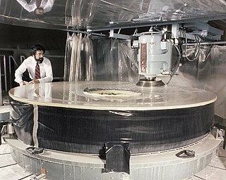
Optical manufacturing and testing spans an enormous range of manufacturing procedures and optical test configurations.

The Corrective Optics Space Telescope Axial Replacement (COSTAR) is an optical correction instrument designed and built by NASA. It was created to correct the spherical aberration of the Hubble Space Telescope's primary mirror, which incorrectly focused light upon the Faint Object Camera (FOC), Faint Object Spectrograph (FOS), and Goddard High Resolution Spectrograph (GHRS) instruments.

In optics, a Mangin mirror is a negative meniscus lens with the reflective surface on the rear side of the glass forming a curved mirror that reflects light without spherical aberration if certain conditions are met. This reflector was invented in 1874 by a French officer Alphonse Mangin as an improved catadioptric reflector for search lights and is also used in other optical devices.

A Fizeau interferometer is an interferometric arrangement whereby two reflecting surfaces are placed facing each other. As seen in Fig 1, the rear-surface reflected light from the transparent first reflector is combined with front-surface reflected light from the second reflector to form interference fringes.
Figuring is the process of final polishing of an optical surface to remove imperfections or modify the surface curvature to achieve the shape required for a given application.
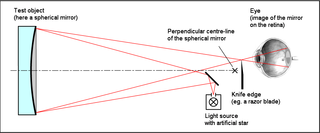
The Foucault knife-edge test is an optical test to accurately measure the shape of concave curved mirrors. It is commonly used by amateur telescope makers for figuring primary mirrors in reflecting telescopes. It uses a relatively simple, inexpensive apparatus compared to other testing techniques.

