Propelling nozzle

Last updated

A propelling nozzle is a nozzle that converts the internal energy of a working gas into propulsive force; it is the nozzle, which forms a jet, that separates a gas turbine, or gas generator, from a jet engine.

Contents

Propelling nozzles accelerate the available gas to subsonic, transonic, or supersonic velocities depending on the power setting of the engine, their internal shape and the pressures at entry to, and exit from, the nozzle. The internal shape may be convergent or convergent-divergent (C-D). C-D nozzles can accelerate the jet to supersonic velocities within the divergent section, whereas a convergent nozzle cannot accelerate the jet beyond sonic speed. [1]

Propelling nozzles may have a fixed geometry, or they may have variable geometry to give different exit areas to control the operation of the engine when equipped with an afterburner or a reheat system. When afterburning engines are equipped with a C-D nozzle the throat area is variable. Nozzles for supersonic flight speeds, at which high nozzle pressure ratios are generated, [2] also have variable area divergent sections. [3] Turbofan engines may have an additional and separate propelling nozzle which further accelerates the bypass air.

Propelling nozzles also act as downstream restrictors, the consequences of which constitute an important aspect of engine design. [4]

Principles of operation

Principal geometries

Convergent nozzle

Convergent nozzles are used on many jet engines. If the nozzle pressure ratio is above the critical value (about 1.8:1) a convergent nozzle will choke, resulting in some of the expansion to atmospheric pressure taking place downstream of the throat (i.e., smallest flow area), in the jet wake. Although jet momentum still produces much of the gross thrust, the imbalance between the throat static pressure and atmospheric pressure still generates some (pressure) thrust.

Divergent nozzle

The supersonic speed of the air flowing into a scramjet allows the use of a simple diverging nozzle

Convergent-divergent (C-D) nozzle

Engines capable of supersonic flight have convergent-divergent exhaust duct features to generate supersonic flow. Rocket engines — the extreme case — owe their distinctive shape to the very high area ratios of their nozzles.

When the pressure ratio across a convergent nozzle exceeds a critical value, the flow chokes, and thus the pressure of the exhaust exiting the engine exceeds the pressure of the surrounding air and cannot decrease via the conventional Venturi effect. This reduces the thrust producing efficiency of the nozzle by causing much of the expansion to take place downstream of the nozzle itself. Consequently, rocket engines and jet engines for supersonic flight incorporate a C-D nozzle which permits further expansion against the inside of the nozzle. However, unlike the fixed convergent-divergent nozzle used on a conventional rocket motor, those on turbojet engines must have heavy and expensive variable geometry to cope with the great variation in nozzle pressure ratio that occurs with speeds from subsonic to over Mach 3.

Nonetheless, low area ratio nozzles have subsonic applications.

Types of nozzle

Variable exhaust nozzle, on the GE F404-400 low-bypass turbofan installed on a Boeing F/A-18 Hornet. Afterburner.jpg
Variable exhaust nozzle, on the GE F404-400 low-bypass turbofan installed on a Boeing F/A-18 Hornet.

Fixed-area nozzle

Non-afterburning subsonic engines have nozzles of a fixed size because the changes in engine performance with altitude and subsonic flight speeds are acceptable with a fixed nozzle. This is not the case at supersonic speeds as described for Concorde below.

With low area ratio

At the other extreme, some high bypass ratio civil turbofans control the fan working line by using a convergent-divergent nozzle with an extremely low (less than 1.01) area ratio on the bypass (or mixed exhaust) stream. At low airspeeds, such a setup causes the nozzle to act as if it had variable geometry by preventing it from choking and allowing it to accelerate and decelerate exhaust gas approaching the throat and divergent section, respectively. Consequently, the nozzle exit area controls the fan match, which, being larger than the throat, pulls the fan working line slightly away from surge. At higher flight speeds, the ram rise in the intake chokes the throat and causes the nozzle's area to dictate the fan match; the nozzle, being smaller than the exit, causes the throat to push the fan working line slightly toward surge. This is not a problem, however, for a fan's surge margin is much greater at high flight speeds.

In rockets (with high area ratio)

Rocket nozzle on V2. Rocket nozzle V2.jpg
Rocket nozzle on V2.

Rocket motors also employ convergent-divergent nozzles, but these are usually of fixed geometry, to minimize weight. Because of the high pressure ratios associated with rocket flight, rocket motor convergent-divergent nozzles have a much greater area ratio (exit/throat) than those fitted to jet engines.

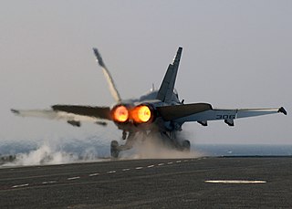
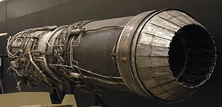
Variable-area for afterburning

The afterburners on combat aircraft require a bigger nozzle to prevent adversely affecting the operation of the engine. The variable area iris [9] nozzle consists of a series of moving, overlapping petals with a nearly circular nozzle cross-section and is convergent to control the operation of the engine. If the aircraft is to fly at supersonic speeds, the afterburner nozzle may be followed by a separate divergent nozzle in an ejector nozzle configuration, as below, or the divergent geometry may be incorporated with the afterburner nozzle in the variable geometry convergent-divergent nozzle configuration, as below.

Early afterburners were either on or off and used a 2-position clamshell, or eyelid, nozzle which gave only one area available for afterburning use. [10]

Ejector

Ejector refers to the pumping action of the very hot, high speed, engine exhaust entraining (ejecting) a surrounding airflow which, together with the internal geometry of the secondary, or diverging, nozzle controls the expansion of the engine exhaust. At subsonic speeds, the airflow constricts the exhaust to a convergent shape. When afterburning is selected and the aircraft speeds up, the two nozzles dilate, which allows the exhaust to form a convergent-divergent shape, speeding the exhaust gasses past Mach 1. More complex engine installations use a tertiary airflow to reduce exit area at low speeds. Advantages of the ejector nozzle are relative simplicity and reliability in cases where the secondary nozzle flaps are positioned by pressure forces. The ejector nozzle is also able to use air which has been ingested by the intake but which is not required by the engine. The amount of this air varies significantly across the flight envelope and ejector nozzles are well suited to matching the airflow between the intake system and engine. Efficient use of this air in the nozzle was a prime requirement for aircraft that had to cruise efficiently at high supersonic speeds for prolonged periods, hence its use in the SR-71, Concorde and XB-70 Valkyrie.

A simple example of ejector nozzle is the fixed geometry cylindrical shroud surrounding the afterburning nozzle on the J85 installation in the T-38 Talon. [11] More complex were the arrangements used for the J58 (SR-71) and TF-30 (F-111) installations. They both used tertiary blow-in doors (open at lower speeds) and free-floating overlapping flaps for a final nozzle. Both the blow-in doors and the final nozzle flaps are positioned by a balance of internal pressure from the engine exhaust and external pressure from the aircraft flowfield.

On early J79 installations (F-104, F-4, A-5 Vigilante), actuation of the secondary nozzle was mechanically linked to the afterburner nozzle. Later installations had the final nozzle mechanically actuated separately from the afterburner nozzle. This gave improved efficiency (better match of primary/secondary exit area with high Mach number requirement) at Mach 2 (B-58 Hustler) and Mach 3 (XB-70). [12]

Variable-geometry convergent-divergent

Turbofan installations which do not require a secondary airflow to be pumped by the engine exhaust use the variable geometry C-D nozzle. [13] These engines don't require the external cooling air needed by turbojets (hot afterburner casing).

The divergent nozzle may be an integral part of the afterburner nozzle petal, an angled extension after the throat. The petals travel along curved tracks and the axial translation and simultaneous rotation increases the throat area for afterburning, while the trailing portion becomes a divergence with bigger exit area for more complete expansion at higher speeds. An example is the TF-30 (F-14). [14]

The primary and secondary petals may be hinged together and actuated by the same mechanism to provide afterburner control and high nozzle pressure ratio expansion as on the EJ200 (Eurofighter). [15] Other examples are found on the F-15, F-16, B-1B.

Additional features

Thrust-vectoring

vectored thrust nozzle Iris vectoring nozzle.jpg
vectored thrust nozzle

Nozzles for vectored thrust include fixed geometry Bristol Siddeley Pegasus and variable geometry F119 (F-22).

Thrust-reversing

The thrust reversers on some engines are incorporated into the nozzle itself and are known as target thrust reversers. The nozzle opens up in two halves which come together to redirect the exhaust partially forward. Since the nozzle area has an influence on the operation of the engine (see below), the deployed thrust reverser has to be spaced the correct distance from the jetpipe to prevent changes in engine operating limits. [16] Examples of target thrust reversers are found on the Fokker 100, Gulfstream IV and Dassault F7X.

Noise-reducing

Jet noise may be reduced by adding features to the exit of the nozzle which increase the surface area of the cylindrical jet. Commercial turbojets and early by-pass engines typically split the jet into multiple lobes. Modern high by-pass turbofans have triangular serrations, called chevrons, which protrude slightly into the propelling jet.

Further topics

The other purpose of the propelling nozzle

The nozzle, by virtue of setting the back-pressure, acts as a downstream restrictor to the compressor, and thus determines what goes into the front of the engine. It shares this function with the other downstream restrictor, the turbine nozzle. [17] The areas of both the propelling nozzle and turbine nozzle set the mass flow through the engine and the maximum pressure. While both these areas are fixed in many engines (i.e. those with a simple fixed propelling nozzle), others, most notably those with afterburning, have a variable area propelling nozzle. This area variation is necessary to contain the disturbing effect on the engine of the high combustion temperatures in the jet pipe, though the area may also be varied during non-afterburning operation to alter the pumping performance of the compressor at lower thrust settings. [4]

For example, if the propelling nozzle were to be removed to convert a turbojet into a turboshaft, the role played by the nozzle area is now taken by the area of the power turbine nozzle guide vanes or stators. [18]

Reasons for C-D nozzle over-expansion and examples

Overexpansion occurs when the exit area is too big relative to the size of the afterburner, or primary, nozzle. [19] This occurred under certain conditions on the J85 installation in the T-38. The secondary or final nozzle was a fixed geometry sized for the maximum afterburner case. At non-afterburner thrust settings the exit area was too big for the closed engine nozzle giving over-expansion. Free-floating doors were added to the ejector allowing secondary air to control the primary jet expansion. [11]

Reasons for C-D nozzle under-expansion and examples

For complete expansion to ambient pressure, and hence maximum nozzle thrust or efficiency, the required area ratio increases with flight Mach number. If the divergence is too short giving too small an exit area the exhaust will not expand to ambient pressure in the nozzle and there will be lost thrust potential [20] With increasing Mach number there may come a point where the nozzle exit area is as big as the engine nacelle diameter or aircraft afterbody diameter. Beyond this point the nozzle diameter becomes the biggest diameter and starts to incur increasing drag. Nozzles are thus limited to the installation size and the loss in thrust incurred is a trade off with other considerations such as lower drag, less weight.

Examples are the F-16 at Mach 2.0 [21] and the XB-70 at Mach 3.0. [22]

Another consideration may relate to the required nozzle cooling flow. The divergent flaps or petals have to be isolated from the afterburner flame temperature, which may be of the order of 3,600 °F (1,980 °C), by a layer of cooling air. A longer divergence means more area to be cooled. The thrust loss from incomplete expansion is traded against the benefits of less cooling flow. This applied to the TF-30 nozzle in the F-14A where the ideal area ratio at Mach 2.4 was limited to a lower value. [23]

What is adding a divergent section worth in real terms?

A divergent section gives added exhaust velocity and hence thrust at supersonic flight speeds. [24]

The effect of adding a divergent section was demonstrated with Pratt & Whitney's first C-D nozzle. The convergent nozzle was replaced with a C-D nozzle on the same engine J57 in the same aircraft F-101. The increased thrust from the C-D nozzle (2,000 lb, 910 kg at sea-level take-off) on this engine raised the speed from Mach 1.6 to almost 2.0 enabling the Air Force to set a world's speed record of 1,207.6 mph (1,943.4 km/h) which was just below Mach 2 for the temperature on that day. The true worth of the C-D nozzle was not realised on the F-101 as the intake was not modified for the higher speeds attainable. [25]

Another example was the replacement of a convergent with a C-D nozzle on the YF-106/P&W J75 when it would not quite reach Mach 2. Together with the introduction of the C-D nozzle, the inlet was redesigned. The USAF subsequently set a world's speed record with the F-106 of 1526 mph (Mach 2.43). [25]

Nozzle area control during dry operation

Sectioned Jumo 004 exhaust nozzle, showing the Zwiebel central plug. Jumo 004 im Technikmuseum Hugo Junkers Dessau 2010-08-06 Detail 03.jpg
Sectioned Jumo 004 exhaust nozzle, showing the Zwiebel central plug.

Some very early jet engines that were not equipped with an afterburner, such as the BMW 003 and the Jumo 004 (which had a design ), [26] had a variable area nozzle formed by a translating plug known as a Zwiebel [wild onion] from its shape. [27] The Jumo 004 had a large area for starting to prevent overheating the turbine and a smaller area for take-off and flight to give higher exhaust velocity and thrust. The 004's Zwiebel possessed a 40 cm (16 in) range of forward/reverse travel to vary the exhaust nozzle area, driven by an electric motor-driven mechanism within the body's divergent area just behind the turbine.

Afterburner-equipped engines may also open the nozzle for starting and at idle. The idle thrust is reduced which lowers taxi speeds and brake wear. This feature on the J75 engine in the F-106 was called 'Idle Thrust Control' and reduced idle thrust by 40%. [28] On aircraft carriers, lower idle thrust reduces the hazards from jet blast.

In some applications, such as the J79 installation in various aircraft, during fast throttle advances, the nozzle area may be prevented from closing beyond a certain point to allow a more rapid increase in RPM [29] and hence faster time to maximum thrust.

In the case of a 2-spool turbojet, such as the Olympus 593 in Concorde, the nozzle area may be varied to enable simultaneous achievement of maximum low-pressure compressor speed and maximum turbine entry temperature over the wide range of engine entry temperatures which occurs with flight speeds up to Mach 2. [30]

On some augmented turbofans the fan operating line is controlled with nozzle area during both dry and wet operation to trade excess surge margin for more thrust.

Nozzle area control during wet operation

The nozzle area is increased during afterburner operation to limit the upstream effects on the engine. To run a turbofan to give maximum airflow (thrust), the nozzle area may be controlled to keep the fan operating line in its optimum position. For a turbojet to give maximum thrust, the area may be controlled to keep the turbine exhaust temperature at its limit. [31]

What happens if the nozzle doesn't open when the afterburner is selected?

In early afterburner installations, the pilot had to check the nozzle position indicator after selecting afterburner. If the nozzle did not open for some reason, and the pilot did not react by cancelling the afterburner selection, typical controls of that period [32] (e.g. the J47 in the F-86L), could cause the turbine blades to overheat and fail. [33]

Other applications

Sketch showing rearward-discharge of gas from exhaust manifold. Avgasrekylator saxofon.png
Sketch showing rearward-discharge of gas from exhaust manifold.

Certain aircraft, like the German Bf 109 and the Macchi C.202/205 were fitted with "ejector-type exhausts". These exhausts converted some of the waste energy of the (internal combustion) engines exhaust-flow into a small amount of forward thrust by accelerating the hot gasses in a rearward direction to a speed greater than that of the aircraft. All exhaust configurations do this to some extent if the exhaust gasses are discharged in a rearward direction.

A particular thrust-producing exhaust device was patented by Rolls-Royce Limited in 1937. [34] On the 1944 de Havilland Hornet's Rolls-Royce Merlin 130/131 engines the thrust from the multi-ejector exhausts were equivalent to an extra 70bhp per-engine at full-throttle height.

See also

Related Research Articles

<span class="mw-page-title-main">Jet engine</span> Aircraft engine that produces thrust by emitting a jet of gas

A jet engine is a type of reaction engine, discharging a fast-moving jet of heated gas that generates thrust by jet propulsion. While this broad definition may include rocket, water jet, and hybrid propulsion, the term jet engine typically refers to an internal combustion air-breathing jet engine such as a turbojet, turbofan, ramjet, pulse jet, or scramjet. In general, jet engines are internal combustion engines.

<span class="mw-page-title-main">Ramjet</span> Supersonic atmospheric jet engine

A ramjet is a form of airbreathing jet engine that requires forward motion of the engine to provide air for combustion. Ramjets work most efficiently at supersonic speeds around Mach 3 and can operate up to Mach 6.

<span class="mw-page-title-main">Turbofan</span> Airbreathing jet engine designed to provide thrust by driving a fan

A turbofan or fanjet is a type of airbreathing jet engine that is widely used in aircraft propulsion. The word "turbofan" is a combination of the preceding generation engine technology of the turbojet, and a reference to the additional fan stage added. It consists of a gas turbine engine which achieves mechanical energy from combustion, and a ducted fan that uses the mechanical energy from the gas turbine to force air rearwards. Thus, whereas all the air taken in by a turbojet passes through the combustion chamber and turbines, in a turbofan some of that air bypasses these components. A turbofan thus can be thought of as a turbojet being used to drive a ducted fan, with both of these contributing to the thrust.

<span class="mw-page-title-main">Turbojet</span> Airbreathing jet engine which is typically used in aircraft

The turbojet is an airbreathing jet engine which is typically used in aircraft. It consists of a gas turbine with a propelling nozzle. The gas turbine has an air inlet which includes inlet guide vanes, a compressor, a combustion chamber, and a turbine. The compressed air from the compressor is heated by burning fuel in the combustion chamber and then allowed to expand through the turbine. The turbine exhaust is then expanded in the propelling nozzle where it is accelerated to high speed to provide thrust. Two engineers, Frank Whittle in the United Kingdom and Hans von Ohain in Germany, developed the concept independently into practical engines during the late 1930s.

<span class="mw-page-title-main">Nozzle</span> Device used to direct the flow of a fluid

A nozzle is a device designed to control the direction or characteristics of a fluid flow as it exits an enclosed chamber or pipe.

<span class="mw-page-title-main">Afterburner</span> Turbojet engine component

An afterburner is an additional combustion component used on some jet engines, mostly those on military supersonic aircraft. Its purpose is to increase thrust, usually for supersonic flight, takeoff, and combat. The afterburning process injects additional fuel into a combustor in the jet pipe behind the turbine, "reheating" the exhaust gas. Afterburning significantly increases thrust as an alternative to using a bigger engine with its attendant weight penalty, but at the cost of increased fuel consumption which limits its use to short periods. This aircraft application of "reheat" contrasts with the meaning and implementation of "reheat" applicable to gas turbines driving electrical generators and which reduces fuel consumption.

<span class="mw-page-title-main">Thrust vectoring</span> Facet of ballistics and aeronautics

Thrust vectoring, also known as thrust vector control (TVC), is the ability of an aircraft, rocket or other vehicle to manipulate the direction of the thrust from its engine(s) or motor(s) to control the attitude or angular velocity of the vehicle.

<span class="mw-page-title-main">Pratt & Whitney F119</span> American low-bypass turbofan engine for the F-22 Raptor

The Pratt & Whitney F119, company designation PW5000, is an afterburning turbofan engine developed by Pratt & Whitney for the Advanced Tactical Fighter (ATF) program, which resulted in the Lockheed Martin F-22 Raptor. The engine delivers thrust in the 35,000 lbf (156 kN) class and was designed for sustained supersonic flight without afterburners, or supercruise. Delivering almost 22% more thrust with 40% fewer parts than its F100 predecessor, the F119 allows the F-22 to achieve supercruise speeds of up to Mach 1.8. The F119's nozzles incorporate thrust vectoring that enable them to direct the engine thrust ±20° in the pitch axis to give the F-22 enhanced maneuverability.

<span class="mw-page-title-main">Pratt & Whitney J58</span> High-speed jet engine by Pratt & Whitney

The Pratt & Whitney J58 is an American jet engine that powered the Lockheed A-12, and subsequently the YF-12 and the SR-71 aircraft. It was an afterburning turbojet engine with a unique compressor bleed to the afterburner that gave increased thrust at high speeds. Because of the wide speed range of the aircraft, the engine needed two modes of operation to take it from stationary on the ground to 2,000 mph (3,200 km/h) at altitude. It was a conventional afterburning turbojet for take-off and acceleration to Mach 2 and then used permanent compressor bleed to the afterburner above Mach 2. The way the engine worked at cruise led it to be described as "acting like a turboramjet". It has also been described as a turboramjet based on incorrect statements describing the turbomachinery as being completely bypassed.

<span class="mw-page-title-main">General Electric J79</span> Axial flow turbojet engine

The General Electric J79 is an axial-flow turbojet engine built for use in a variety of fighter and bomber aircraft and a supersonic cruise missile. The J79 was produced by General Electric Aircraft Engines in the United States, and under license by several other companies worldwide. Among its major uses was the Lockheed F-104 Starfighter, Convair B-58 Hustler, McDonnell Douglas F-4 Phantom II, North American A-5 Vigilante and IAI Kfir.

A jet engine performs by converting fuel into thrust. How well it performs is an indication of what proportion of its fuel goes to waste. It transfers heat from burning fuel to air passing through the engine. In doing so it produces thrust work when propelling a vehicle but a lot of the fuel is wasted and only appears as heat. Propulsion engineers aim to minimize the degradation of fuel energy into unusable thermal energy. Increased emphasis on performance improvements for commercial airliners came in the 1970s from the rising cost of fuel.

<span class="mw-page-title-main">General Electric YF120</span> American fighter variable-cycle turbofan engine

The General Electric YF120, internally designated as GE37, was a variable cycle afterburning turbofan engine designed by General Electric Aircraft Engines in the late 1980s and early 1990s for the United States Air Force's Advanced Tactical Fighter (ATF) program. It was designed to produce maximum thrust in the 35,000 lbf (156 kN) class. Prototype engines were installed in the two competing technology demonstrator aircraft, the Lockheed YF-22 and Northrop YF-23.

<span class="mw-page-title-main">Variable cycle engine</span> Aircraft propulsion system efficient at a range of speeds higher and lower than sounds

A variable cycle engine (VCE), also referred to as adaptive cycle engine (ACE), is an aircraft jet engine that is designed to operate efficiently under mixed flight conditions, such as subsonic, transonic and supersonic.

<span class="mw-page-title-main">Rolls-Royce/Snecma Olympus 593</span> 1960s British/French turbojet aircraft engine

The Rolls-Royce/Snecma Olympus 593 was an Anglo-French turbojet with reheat, which powered the supersonic airliner Concorde. It was initially a joint project between Bristol Siddeley Engines Limited (BSEL) and Snecma, derived from the Bristol Siddeley Olympus 22R engine. Rolls-Royce Limited acquired BSEL in 1966 during development of the engine, making BSEL the Bristol Engine Division of Rolls-Royce.

<span class="mw-page-title-main">Components of jet engines</span> Brief description of components needed for jet engines

This article briefly describes the components and systems found in jet engines.

<span class="mw-page-title-main">Volvo RM8</span>

The Volvo RM8 is a low-bypass afterburning turbofan jet engine developed for the Saab 37 Viggen fighter. An augmented bypass engine was required to give both better fuel consumption at cruise speeds and higher thrust boosting for its short take-off requirement than would be possible using a turbojet. In 1962, the civil Pratt & Whitney JT8D engine, as used for airliners such as the Boeing 727, was chosen as the only engine available which could be modified to meet the Viggen requirements. The RM8 was a licensed-built version of the JT8D, but extensively modified for supersonic speeds, with a Swedish-designed afterburner, and was produced by Svenska Flygmotor.

An airbreathing jet engine is a jet engine in which the exhaust gas which supplies jet propulsion is atmospheric air, which is taken in, compressed, heated, and expanded back to atmospheric pressure through a propelling nozzle. Compression may be provided by a gas turbine, as in the original turbojet and newer turbofan, or arise solely from the ram pressure of the vehicle's velocity, as with the ramjet and pulsejet.

The familiar study of jet aircraft treats jet thrust with a "black box" description which only looks at what goes into the jet engine, air and fuel, and what comes out, exhaust gas and an unbalanced force. This force, called thrust, is the sum of the momentum difference between entry and exit and any unbalanced pressure force between entry and exit, as explained in "Thrust calculation".

<span class="mw-page-title-main">General Electric Affinity</span> Supersonic aircraft engine design

The General Electric Affinity was a turbofan developed by GE Aviation for supersonic transports. Conceived in May 2017 to power the Aerion AS2 supersonic business jet, initial design was completed in 2018 and detailed design in 2020 for the first prototype production. GE Aviation discontinued development of the engine in May 2021. Its high-pressure core is derived from the CFM56, matched to a new twin fan low-pressure section for a reduced bypass ratio better suited to supersonic flight.

<span class="mw-page-title-main">Boom Symphony</span> Supersonic turbofan engine design

The Boom Symphony is a medium-bypass turbofan engine under development by Boom Technology for use on its Overture supersonic airliner. The engine is designed to produce 35,000 pounds of thrust at takeoff, sustain Overture supercruise at Mach 1.7, and burn sustainable aviation fuel exclusively.

References

  1. "Jet Propulsion for Aerospace Applications" second edition, Hesse and Mumford, Pitman Publishing Corporation p136
  2. "Nozzle Selection and Design Criteria"AIAA 2004-3923, Fig11
  3. "Nozzle Selection and Design Criteria"AIAA 2004-3923
  4. 1 2 "Jet Propulsion" Nicholas Cumpsty, ISBN   0 521 59674 2, p144
  5. "Jet Propulsion" Nicholas Cumpsty, ISBN   0 521 59674 2, p243
  6. "Exhaust nozzles for Propulsion Systems with Emphasis on Supersonic Aircraft" Leonard E. Stitt, NASA Reference Publication 1235, May 1990, para 2.2.9
  7. J79-15/-17 Turbojet Accident Investigation Procedures, Technical Report ASD-TR-75-19, Aeronautical Systems Division, Wright-Patterson Air Force Base Ohio, Fig60 "Nozzle area v Throttle angle
  8. "Flight Manual MIG-29" Luftwaffenmaterialkommando GAF T.O.1F-MIG-29-1, Figure1-6 "Primary nozzle area v throttle angle"
  9. "Variable Ejector For Iris Nozzles" C. R. Brown U.S. Patent 2,870,600
  10. "Afterburning A Review of Current American Practice" Flight magazine 21 November 1952 p648, Flightglobal Archive website
  11. 1 2 "J85 Rejuvenation Through Technology Insertion" Brisken, Howell, Ewing, G.E.Aircraft Engines, Cincinnati, Ohio, OH45215, USA
  12. "Variable-Geometry Exhaust Nozzles and Their Effects on Airplane Performance" R. C. Ammer and W.F. Punch, SAE680295
  13. "Design for Air Combat"Ray Whitford ISBN   0 7106 0426 2 p207
  14. "F-14A Installed Nozzle Performance" W.C. Schnell, Grumman Aerospace Corporation, AIAA Paper No. 74-1099
  15. "http://ftp.rta.nato.int/public/PubFullText/RTO/MP/RTO-MP-008/$MP-008-20.pdf Archived 2016-03-04 at the Wayback Machine
  16. "Design and Testing of a Common Engine and Nacelle for the Fokker 100 and Gulfstream Airplanes" H.Nawrocki, J.van Hengst, L.de Hzaij, AIAA-89-2486
  17. Whittle, Frank (1981). Gas turbine aero-thermodynamics : with special reference to aircraft propulsion. Pergamon Press. p. 83. ISBN   9780080267197.
  18. "Gas Turbine Theory" Cohen, Rogers, Saravanamuttoo, ISBN   0 582 44927 8, p242
  19. "Nozzle selection and design criteria" AIAA 2004-3923, Fig.14 "Over-expanded nozzle"
  20. "Nozzle Selection and Design criteria" AIAA 2004-3923, fig.15
  21. "Design for Air Combat"Ray Whitford ISBN   0 7106 0426 2 Fig 226
  22. SAE 680295 "Variable Geometry Exhaust Nozzles and their Effects on Airplane Performance"
  23. "F-14A Installed Nozzle Performance"by W.C. Schnell, AIAA Paper No. 74-1099, Fig.5 "Effect of cooling flow on nozzle performance"
  24. "Nozzle Selection and Design criteria" AIAA 2004-3923, p4
  25. 1 2 "Test Pilot" edited by Harry Schmidt, "Mach 2 Books" Shelton CT 06484
  26. Christopher, John. The Race for Hitler's X-Planes (The Mill, Gloucestershire: History Press, 2013), p.70.
  27. "Jet Propulsion Progress" Leslie E. neville and Nathaniel F. Silsbee, first edition, McGraw-Hill Book Company, Inc. 1948
  28. "Flight Manual F-106A and F-106B aircraft" T.O. 1F-106A-1
  29. "Flight Manual USAF F-4E Series Aircraft" TO 1F-4E-1, 1 February 1979,"Exhaust Nozzle Control Unit"P1-8
  30. "Jet Propulsion" Nicholas Cumpsty, ISBN   0 521 59674 2
  31. U.S.Patent 3,656,301 "Compensated feedback gas turbine augmentation control system" Herbert Katz, General Electric Company
  32. "U.S.Patent 3,080,707,"Afterburner fuel and nozzle area control"
  33. "Testing Death" George J. Marrett, ISBN   978-1-59114-512-7
  34. "Exhaust pipe for internal combustion engines of aircraft".