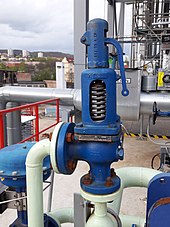
A relief valve or pressure relief valve (PRV) is a type of safety valve used to control or limit the pressure in a system; excessive pressure might otherwise build up and create a process upset, instrument or equipment failure, explosion, or fire.
A relief valve or pressure relief valve (PRV) is a type of safety valve used to control or limit the pressure in a system; excessive pressure might otherwise build up and create a process upset, instrument or equipment failure, explosion, or fire.
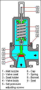
Excess pressure is relieved by allowing the pressurized fluid to flow from an auxiliary passage out of the system. The relief valve is designed or set to open at a predetermined set pressure to protect pressure vessels and other equipment from being subjected to pressures that exceed their design limits. When the set pressure is exceeded, the relief valve becomes the "path of least resistance" as the valve is forced open and a portion of the fluid is diverted through the auxiliary route.
In systems containing flammable fluids, the diverted fluid (liquid, gas or liquid-gas mixture) is either recaptured [1] by a low pressure, high-flow vapor recovery system or is routed through a piping system known as a flare header or relief header to a central, elevated gas flare where it is burned, releasing naked combustion gases into the atmosphere. [2] In non-hazardous systems, the fluid is often discharged to the atmosphere by a suitable discharge pipework designed to prevent rainwater ingress which can affect the set lift pressure, and positioned not to cause a hazard to personnel.
As the fluid is diverted, the pressure inside the vessel will stop rising. Once it reaches the valve's reseating pressure, the valve will close. The blowdown is usually stated as a percentage of set pressure and refers to how much the pressure needs to drop before the valve reseats. The blowdown can vary roughly 2–20%, and some valves have adjustable blowdowns.
In high-pressure gas systems, it is recommended that the outlet of the relief valve be in the open air. In systems where the outlet is connected to piping, the opening of a relief valve will give a pressure build-up in the piping system downstream of the relief valve. This often means that the relief valve will not re-seat once the set pressure is reached. For these systems often so-called "differential" relief valves are used. This means that the pressure is only working on an area that is much smaller than the area of the opening of the valve. If the valve is opened, the pressure has to decrease enormously before the valve closes and also the outlet pressure of the valve can easily keep the valve open. Another consideration is that if other relief valves are connected to the outlet pipe system, they may open as the pressure in the exhaust pipe system increases. This may cause undesired operation.
In some cases, a so-called bypass valve acts as a relief valve by being used to return all or part of the fluid discharged by a pump or gas compressor back to either a storage reservoir or the inlet of the pump or gas compressor. This is done to protect the pump or gas compressor and any associated equipment from excessive pressure. The bypass valve and bypass path can be internal (an integral part of the pump or compressor) or external (installed as a component in the fluid path). Many fire engines have such relief valves to prevent the overpressurization of fire hoses.
In other cases, equipment must be protected against being subjected to an internal vacuum (i.e., low pressure) that is lower than the equipment can withstand. In such cases, vacuum relief valves are used to open at a predetermined low-pressure limit and to admit air or an inert gas into the equipment to control the amount of vacuum.
In the petroleum refining, petrochemical and chemical manufacturing, natural gas processing and power generation industries, the term relief valve is associated with the terms pressure relief valve (PRV), pressure safety valve (PSV) and safety valve:
In most countries, industries are legally required to protect pressure vessels and other equipment by using relief valves. Also in most countries, equipment design codes such as those provided by the American Society of Mechanical Engineers (ASME), American Petroleum Institute (API) and other organizations like ISO (ISO 4126) must be complied with and those codes include design standards for relief valves. [3] [4]
The main standards, laws, or directives are:
Formed in 1977, the Design Institute for Emergency Relief Systems [5] was a consortium of 29 companies under the auspices of the American Institute of Chemical Engineers (AIChE) that developed methods for the design of emergency relief systems to handle runaway reactions. Its purpose was to develop the technology and methods needed for sizing pressure relief systems for chemical reactors, particularly those in which exothermic reactions are carried out. Such reactions include many classes of industrially important processes including polymerizations, nitrations, diazotizations, sulphonations, epoxidations, aminations, esterifications, neutralizations, and many others. Pressure relief systems can be difficult to design, not least because what is expelled can be gas/vapor, liquid, or a mixture of the two – just as with a can of carbonated drink when it is suddenly opened. For chemical reactions, it requires extensive knowledge of both chemical reaction hazards and fluid flow.
DIERS has investigated the two-phase vapor-liquid onset/disengagement dynamics and the hydrodynamics of emergency relief systems with extensive experimental and analysis work. [6] Of particular interest to DIERS were the prediction of two-phase flow venting and the applicability of various sizing methods for two-phase vapor-liquid flashing flow. DIERS became a user's group in 1985.
European DIERS Users' Group (EDUG) [7] is a group of mainly European industrialists, consultants and academics who use the DIERS technology. The EDUG started in the late 1980s and has an annual meeting. A summary of many of key aspects of the DIERS technology has been published in the UK by the HSE. [8]

A boiler is a closed vessel in which fluid is heated. The fluid does not necessarily boil. The heated or vaporized fluid exits the boiler for use in various processes or heating applications, including water heating, central heating, boiler-based power generation, cooking, and sanitation.

A safety valve is a valve that acts as a fail-safe. An example of safety valve is a pressure relief valve (PRV), which automatically releases a substance from a boiler, pressure vessel, or other system, when the pressure or temperature exceeds preset limits. Pilot-operated relief valves are a specialized type of pressure safety valve. A leak tight, lower cost, single emergency use option would be a rupture disk.

A pressure vessel is a container designed to hold gases or liquids at a pressure substantially different from the ambient pressure.

A boiling liquid expanding vapor explosion is an explosion caused by the rupture of a vessel containing a pressurized liquid that has reached a temperature above its boiling point. Because the boiling point of a liquid rises with pressure, the contents of the pressurized vessel can remain a liquid as long as the vessel is intact. If the vessel's integrity is compromised, the loss of pressure drops the boiling point, which can cause the liquid to convert to a gas expanding rapidly. If the gas is combustible, as in the case with hydrocarbons and alcohols, further damage can be caused by the ensuing fire.
A gas lift or bubble pump is a type of pump that can raise fluid between elevations by introducing gas bubbles into a vertical outlet tube; as the bubbles rise within the tube they cause a drop in the hydrostatic pressure behind them, causing the fluid to be pulled up. Gas lifts are commonly used as artificial lifts for water or oil, using compressed air or water vapor.

A chemical plant is an industrial process plant that manufactures chemicals, usually on a large scale. The general objective of a chemical plant is to create new material wealth via the chemical or biological transformation and or separation of materials. Chemical plants use specialized equipment, units, and technology in the manufacturing process. Other kinds of plants, such as polymer, pharmaceutical, food, and some beverage production facilities, power plants, oil refineries or other refineries, natural gas processing and biochemical plants, water and wastewater treatment, and pollution control equipment use many technologies that have similarities to chemical plant technology such as fluid systems and chemical reactor systems. Some would consider an oil refinery or a pharmaceutical or polymer manufacturer to be effectively a chemical plant.
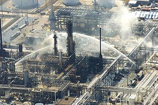
The Texas City Refinery explosion occurred on March 23, 2005, when a vapor cloud of natural gas and petroleum ignited and violently exploded at the isomerization (ISOM) process unit at the BP Texas City refinery in Texas City, Texas, killing 15 workers, injuring 180 others and severely damaging the refinery. The Texas City Refinery was the second-largest oil refinery in the state, and the third-largest in the United States with an input capacity of 437,000 barrels (69,500 m3) per day as of January 1, 2000. BP acquired the Texas City refinery as part of its merger with Amoco in 1999.
A liquid-ring pump is a rotating positive-displacement gas pump, with liquid under centrifugal force acting as a seal.

Vapour-compression refrigeration or vapor-compression refrigeration system (VCRS), in which the refrigerant undergoes phase changes, is one of the many refrigeration cycles and is the most widely used method for air conditioning of buildings and automobiles. It is also used in domestic and commercial refrigerators, large-scale warehouses for chilled or frozen storage of foods and meats, refrigerated trucks and railroad cars, and a host of other commercial and industrial services. Oil refineries, petrochemical and chemical processing plants, and natural gas processing plants are among the many types of industrial plants that often utilize large vapor-compression refrigeration systems. Cascade refrigeration systems may also be implemented using two compressors.
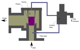
Like other pressure relief valves (PRV), pilot-operated relief valves (PORV) are used for emergency relief during overpressure events. PORV are also called pilot-operated safety valve (POSV), pilot-operated pressure relief valve (POPRV), or pilot-operated safety relief valve (POSRV), depending on the manufacturer and the application. Technically POPRV is the most generic term, but PORV is often used generically even though it should refer to valves in liquid service.
A blowdown stack is an elevated vent or vertical stack that is used to vent the pressure of components of a chemical, refinery or other plant if there is a process problem or emergency. A blowdown stack can be used to complement a flare stack or as an alternative. The purpose is to prevent 'loss of containment' of volatile liquids and gases. Blowdown from several systems may be combined in a blowdown header prior to the stack. A knock-out pot may be provided at the base of the stack to remove any liquids. Blowdown stacks may either be ignited or un-ignited. The height of the blowdown stack must be tall enough to ensure the safe dispersal of vapour.
An oil production plant is a facility which processes production fluids from oil wells in order to separate out key components and prepare them for export. Typical oil well production fluids are a mixture of oil, gas and produced water. An oil production plant is distinct from an oil depot, which does not have processing facilities.
The term separator in oilfield terminology designates a pressure vessel used for separating well fluids produced from oil and gas wells into gaseous and liquid components. A separator for petroleum production is a large vessel designed to separate production fluids into their constituent components of oil, gas and water. A separating vessel may be referred to in the following ways: Oil and gas separator, Separator, Stage separator, Trap, Knockout vessel, Flash chamber, Expansion separator or expansion vessel, Scrubber, Filter. These separating vessels are normally used on a producing lease or platform near the wellhead, manifold, or tank battery to separate fluids produced from oil and gas wells into oil and gas or liquid and gas. An oil and gas separator generally includes the following essential components and features:
A shutdown valve is an actuated valve designed to stop the flow of a hazardous fluid upon the detection of a dangerous event. This provides protection against possible harm to people, equipment or the environment. Shutdown valves form part of a safety instrumented system. The process of providing automated safety protection upon the detection of a hazardous event is called functional safety.

In chemical engineering, a vapor–liquid separator is a device used to separate a vapor–liquid mixture into its constituent phases. It can be a vertical or horizontal vessel, and can act as a 2-phase or 3-phase separator.
A high-integrity pressure protection system (HIPPS) is a type of safety instrumented system (SIS) designed to prevent over-pressurization of a plant, such as a chemical plant or oil refinery. The HIPPS will shut off the source of the high pressure before the design pressure of the system is exceeded, thus preventing loss of containment through rupture (explosion) of a line or vessel. Therefore, a HIPPS is considered as a barrier between a high-pressure and a low-pressure section of an installation.
The Glossary of fuel cell terms lists the definitions of many terms used within the fuel cell industry. The terms in this fuel cell glossary may be used by fuel cell industry associations, in education material and fuel cell codes and standards to name but a few.

An industrial safety system is a countermeasure crucial in any hazardous plants such as oil and gas plants and nuclear plants. They are used to protect human, industrial plant, and the environment in case of the process going beyond the allowed control margins.
Surge control is the use of different techniques and equipment in a hydraulic system to prevent any excessive gain in pressure that would cause the hydraulic process pressure to exceed the maximum working pressure of the mechanical equipment used in the system.

Instrumentation is used to monitor and control the process plant in the oil, gas and petrochemical industries. Instrumentation ensures that the plant operates within defined parameters to produce materials of consistent quality and within the required specifications. It also ensures that the plant is operated safely and acts to correct out of tolerance operation and to automatically shut down the plant to prevent hazardous conditions from occurring. Instrumentation comprises sensor elements, signal transmitters, controllers, indicators and alarms, actuated valves, logic circuits and operator interfaces.
