Robot calibration

Last updated

Robot calibration is a process used to improve the accuracy of robots, particularly industrial robots which are highly repeatable but not accurate. Robot calibration is the process of identifying certain parameters in the kinematic structure of an industrial robot, such as the relative position of robot links. Depending on the type of errors modeled, the calibration can be classified in three different ways. Level-1 calibration only models differences between actual and reported joint displacement values, (also known as mastering). Level-2 calibration, also known as kinematic calibration, concerns the entire geometric robot calibration which includes angle offsets and joint lengths. Level-3 calibration, also called a non-kinematic calibration, models errors other than geometric defaults such as stiffness, joint compliance, and friction. Often Level-1 and Level-2 calibration are sufficient for most practical needs. [1] [2]

Contents

Parametric robot calibration is the process of determining the actual values of kinematic and dynamic parameters of an industrial robot (IR). Kinematic parameters describe the relative position and orientation of links and joints in the robot while the dynamic parameters describe arm and joint masses and internal friction. [3]

Non-parametric robot calibration circumvents the parameter identification. Used with serial robots, it is based on the direct compensation of mapped errors in the workspace. Used with parallel robots, non-parametric calibration can be performed by the transformation of the configuration space.

Robot calibration can remarkably improve the accuracy of robots programmed offline. A calibrated robot has a higher absolute as well as relative positioning accuracy compared to an uncalibrated one; i.e., the real position of the robot end effector corresponds better to the position calculated from the mathematical model of the robot. Absolute positioning accuracy is particularly relevant in connection with robot exchangeability and off-line programming of precision applications. Besides the calibration of the robot, the calibration of its tools and the workpieces it works with (the so-called cell calibration) can minimize occurring inaccuracies and improve process security.

Accuracy criteria and error sources

The international standard ISO 9283 [4] sets different performance criteria for industrial robots and suggests test procedures in order to obtain appropriate parameter values. The most important criteria, and also the most commonly used, are pose accuracy (AP) and pose repeatability (RP). Repeatability is particularly important when the robot is moved towards the command positions manually ("Teach-In"). If the robot program is generated by a 3D simulation (off-line programming), absolute accuracy is vital, too. Both are generally influenced negatively by kinematic factors. Here especially the joint offsets and deviations in lengths and angles between the individual robot links take effect.

Measurement systems

There exist different possibilities for pose measurement with industrial robots, e.g. touching reference parts, using supersonic distance sensors, laser interferometry, theodolites, calipers or laser triangulation. Furthermore, there are camera systems which can be attached in the robot's cell or at the IR mounting plate and acquire the pose of a reference object. Measurement and calibration systems are made by such companies as Bluewrist, Dynalog, RoboDK, FARO Technologies, Creaform, Leica, Cognibotics, Metris, Metronor, Wiest, Teconsult [5] and Automated Precision.

Mathematical principles

Objective function and optimization problem Formeln.png
Objective function and optimization problem

The robot errors gathered by pose measurements can be minimized by numerical optimization. For kinematic calibration, a complete kinematical model of the geometric structure must be developed, whose parameters can then be calculated by mathematical optimization. The common system behaviour can be described with the vector model function as well as input and output vectors (see figure). The variables k, l, m, n and their derivates describe the dimensions of the single vector spaces. Minimization of the residual error r for identification of the optimal parameter vector p follows from the difference between both output vectors using the Euclidean norm.

For solving the kinematical optimization problems least-squares descent methods are convenient, e.g. a modified quasi-Newton method. This procedure supplies corrected kinematical parameters for the measured machine, which then, for example, can be used to update the system variables in the controller to adapt the used robot model to the real kinematics. [6]

Results

Positioning accuracy of a Tricept robot before and after calibration Tricept-Result.png
Positioning accuracy of a Tricept robot before and after calibration

The positioning accuracy of industrial robots varies by manufacturer, age, and robot type. Using kinematic calibration, these errors can be reduced to less than a millimeter in most cases. An example of this is shown in the figure to the right.

Accuracy of 6-axis industrial robots can improved by a factor of 10. [7]

Accuracy of parallel robots after calibration can be as low as a tenth of a millimeter.

Sample applications

In-line measurement cell for car body inspection Robot measurement.png
In-line measurement cell for car body inspection

In the industry, there is a general trend towards substitution of machine tools and special machines by industrial robots for certain manufacturing tasks whose accuracy demands can be fulfilled by calibrated robots. Through simulation and off-line programming, it is possible to easily accomplish complex programming tasks, such as robot machining. However, contrary to the teach programming method, good accuracy as well as repeatability is required.

In the figure, a current example is shown: In-line measurement in automotive manufacturing, where the common "measurement tunnel" used for 100% inspection with many expensive sensors are partly replaced by industrial robots that carry only one sensor each. This way the total costs of a measurement cell can be reduced significantly. The station can also be re-used after a model change by simple re-programming without mechanical adaptations.

Further examples for precision applications are robot-guided hemming in car body manufacturing, assembly of mobile phones, drilling, riveting and milling in the aerospace industry, and increasingly in medical applications.

See also


Literature

Related Research Articles

<span class="mw-page-title-main">Industrial robot</span> Robot used in manufacturing

An industrial robot is a robot system used for manufacturing. Industrial robots are automated, programmable and capable of movement on three or more axes.

<span class="mw-page-title-main">Inverse kinematics</span> Computing joint values of a kinematic chain from a known end position

In computer animation and robotics, inverse kinematics is the mathematical process of calculating the variable joint parameters needed to place the end of a kinematic chain, such as a robot manipulator or animation character's skeleton, in a given position and orientation relative to the start of the chain. Given joint parameters, the position and orientation of the chain's end, e.g. the hand of the character or robot, can typically be calculated directly using multiple applications of trigonometric formulas, a process known as forward kinematics. However, the reverse operation is, in general, much more challenging.

<span class="mw-page-title-main">Robot kinematics</span> Geometric analysis of multi-DoF kinematic chains that model a robot

In robotics, robot kinematics applies geometry to the study of the movement of multi-degree of freedom kinematic chains that form the structure of robotic systems. The emphasis on geometry means that the links of the robot are modeled as rigid bodies and its joints are assumed to provide pure rotation or translation.

<span class="mw-page-title-main">Coordinate-measuring machine</span> Device for measuring the geometry of objects

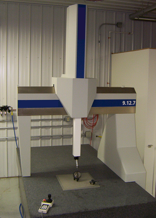
A coordinate-measuring machine (CMM) is a device that measures the geometry of physical objects by sensing discrete points on the surface of the object with a probe. Various types of probes are used in CMMs, the most common being mechanical and laser sensors, though optical and white light sensors do exist. Depending on the machine, the probe position may be manually controlled by an operator, or it may be computer controlled. CMMs typically specify a probe's position in terms of its displacement from a reference position in a three-dimensional Cartesian coordinate system. In addition to moving the probe along the X, Y, and Z axes, many machines also allow the probe angle to be controlled to allow measurement of surfaces that would otherwise be unreachable.

<span class="mw-page-title-main">Articulated robot</span>

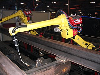
An articulated robot is a robot with rotary joints. Articulated robots can range from simple two-jointed structures to systems with 10 or more interacting joints and materials. They are powered by a variety of means, including electric motors.

<span class="mw-page-title-main">Network analyzer (electrical)</span> Instrument that measures the network parameters of electrical networks

A network analyzer is an instrument that measures the network parameters of electrical networks. Today, network analyzers commonly measure s–parameters because reflection and transmission of electrical networks are easy to measure at high frequencies, but there are other network parameter sets such as y-parameters, z-parameters, and h-parameters. Network analyzers are often used to characterize two-port networks such as amplifiers and filters, but they can be used on networks with an arbitrary number of ports.

Camera resectioning is the process of estimating the parameters of a pinhole camera model approximating the camera that produced a given photograph or video; it determines which incoming light ray is associated with each pixel on the resulting image. Basically, the process determines the pose of the pinhole camera.

<span class="mw-page-title-main">Serial manipulator</span>

Serial manipulators are the most common industrial robots and they are designed as a series of links connected by motor-actuated joints that extend from a base to an end-effector. Often they have an anthropomorphic arm structure described as having a "shoulder", an "elbow", and a "wrist".

<span class="mw-page-title-main">Parallel manipulator</span>

A parallel manipulator is a mechanical system that uses several computer-controlled serial chains to support a single platform, or end-effector. Perhaps, the best known parallel manipulator is formed from six linear actuators that support a movable base for devices such as flight simulators. This device is called a Stewart platform or the Gough-Stewart platform in recognition of the engineers who first designed and used them.

<span class="mw-page-title-main">Robotic arm</span> Type of mechanical arm with similar functions to a human arm.

A robotic arm is a type of mechanical arm, usually programmable, with similar functions to a human arm; the arm may be the sum total of the mechanism or may be part of a more complex robot. The links of such a manipulator are connected by joints allowing either rotational motion or translational (linear) displacement. The links of the manipulator can be considered to form a kinematic chain. The terminus of the kinematic chain of the manipulator is called the end effector and it is analogous to the human hand. However, the term "robotic hand" as a synonym of the robotic arm is often proscribed.

There are many conventions used in the robotics research field. This article summarises these conventions.

Visual servoing, also known as vision-based robot control and abbreviated VS, is a technique which uses feedback information extracted from a vision sensor to control the motion of a robot. One of the earliest papers that talks about visual servoing was from the SRI International Labs in 1979.

<span class="mw-page-title-main">Glossary of robotics</span> List of definitions of terms and concepts commonly used in the study of robotics

Robotics is the branch of technology that deals with the design, construction, operation, structural disposition, manufacture and application of robots. Robotics is related to the sciences of electronics, engineering, mechanics, and software.

<span class="mw-page-title-main">RoboLogix</span> Robotics simulator

RoboLogix is a robotics simulator which uses a physics engine to emulate robotics applications. The advantages of using robotics simulation tools such as RoboLogix are that they save time in the design of robotics applications and they can also increase the level of safety associated with robotic equipment since various "what if" scenarios can be tried and tested before the system is activated. RoboLogix provides a platform to teach, test, run, and debug programs that have been written using a five-axis industrial robot in a range of applications and functions. These applications include pick-and-place, palletizing, welding, and painting.

The following outline is provided as an overview of and topical guide to robotics:

Length measurement, distance measurement, or range measurement (ranging) refers to the many ways in which length, distance, or range can be measured. The most commonly used approaches are the rulers, followed by transit-time methods and the interferometer methods based upon the speed of light.

Kinematics equations are the constraint equations of a mechanical system such as a robot manipulator that define how input movement at one or more joints specifies the configuration of the device, in order to achieve a task position or end-effector location. Kinematics equations are used to analyze and design articulated systems ranging from four-bar linkages to serial and parallel robots.

RoboDK is an offline programming and simulation software for industrial robots. The simulation software can be used for many manufacturing projects including milling, welding, pick and place, packaging and labelling, palletizing, painting, robot calibration and more.

In robotics, Cartesian parallel manipulators are manipulators that move a platform using parallel-connected kinematic linkages ('limbs') lined up with a Cartesian coordinate system. Multiple limbs connect the moving platform to a base. Each limb is driven by a linear actuator and the linear actuators are mutually perpendicular. The term 'parallel' here refers to the way that the kinematic linkages are put together, it does not connote geometrically parallel; i.e., equidistant lines.

<span class="mw-page-title-main">Force control</span> Force control is given by the machine

Force control is the control of the force with which a machine or the manipulator of a robot acts on an object or its environment. By controlling the contact force, damage to the machine as well as to the objects to be processed and injuries when handling people can be prevented. In manufacturing tasks, it can compensate for errors and reduce wear by maintaining a uniform contact force. Force control achieves more consistent results than position control, which is also used in machine control. Force control can be used as an alternative to the usual motion control, but is usually used in a complementary way, in the form of hybrid control concepts. The acting force for control is usually measured via force transducers or estimated via the motor current.

References

  1. Nubiola, Albert; Bonev, Ilian A. (2013-02-01). "Absolute calibration of an ABB IRB 1600 robot using a laser tracker". Robotics and Computer-Integrated Manufacturing. 29 (1): 236–245. doi:10.1016/j.rcim.2012.06.004.
  2. Nof, Shimon Y (1999). Handbook of industrial robotics (Vol 1 ed.). Wiley and Sons. pp. 72–74.
  3. Lightcap, C.; Banks, S. (2007-10-01). "Dynamic identification of a mitsubishi pa10-6ce robot using motion capture". 2007 IEEE/RSJ International Conference on Intelligent Robots and Systems. pp. 3860–3865. doi:10.1109/IROS.2007.4399425. ISBN   978-1-4244-0911-2. S2CID   14339917.
  4. "ISO 9283:1998 - Manipulating industrial robots -- Performance criteria and related test methods". ISO. Retrieved 2017-01-03.
  5. "Helmut Schmidt University".
  6. "Parallel Kinematics Calibration Without Parameter Identification". Scribd. Retrieved 2017-01-03.
  7. RoboDK. "Robot calibration - RoboDK". www.robodk.com. Retrieved 2017-01-03.