Turbomachinery

Last updated
Mounting of a steam turbine produced by Siemens, Germany Dampfturbine Montage01.jpg
Mounting of a steam turbine produced by Siemens, Germany
Aircraft engine, in this case a Boeing 777 engine N7771@GVA;09.09.1995-engine (6083468531).jpg
Aircraft engine, in this case a Boeing 777 engine

Turbomachinery, in mechanical engineering, describes machines that transfer energy between a rotor and a fluid, including both turbines and compressors. While a turbine transfers energy from a fluid to a rotor, a compressor transfers energy from a rotor to a fluid. [1] [2] It is an important application of fluid mechanics. [3]

Contents

These two types of machines are governed by the same basic relationships including Newton's second Law of Motion and Euler's pump and turbine equation for compressible fluids. Centrifugal pumps are also turbomachines that transfer energy from a rotor to a fluid, usually a liquid, while turbines and compressors usually work with a gas. [1]

History

The first turbomachines could be identified as water wheels, which appeared between the 3rd and 1st centuries BCE in the Mediterranean region. These were used throughout the medieval period and began the first Industrial Revolution. When steam power started to be used, as the first power source driven by the combustion of a fuel rather than renewable natural power sources, this was as reciprocating engines. Primitive turbines and conceptual designs for them, such as the smoke jack, appeared intermittently but the temperatures and pressures required for a practically efficient turbine exceeded the manufacturing technology of the time. The first patent for gas turbines were filed in 1791 by John Barber. Practical hydroelectric water turbines and steam turbines did not appear until the 1880s. Gas turbines appeared in the 1930s.

The first impulse type turbine was created by Carl Gustaf de Laval in 1883. This was closely followed by the first practical reaction type turbine in 1884, built by Charles Parsons. Parsons’ first design was a multi-stage axial-flow unit, which George Westinghouse acquired and began manufacturing in 1895, while General Electric acquired de Laval's designs in 1897. Since then, development has skyrocketed from Parsons’ early design, producing 0.746 kW, to modern nuclear steam turbines producing upwards of 1500 MW. Furthermore, steam turbines accounted for roughly 45% of electrical power generated in the United States in 2021. [4] Then the first functioning industrial gas turbines were used in the late 1890s to power street lights (Meher-Homji, 2000).

Classification

A steam turbine from MAN SE subsidiary MAN Turbo SteamTurbine.jpg
A steam turbine from MAN SE subsidiary MAN Turbo

In general, the two kinds of turbomachines encountered in practice are open and closed turbomachines. Open machines such as propellers, windmills, and unshrouded fans act on an infinite extent of fluid, whereas closed machines operate on a finite quantity of fluid as it passes through a housing or casing. [2]

Turbomachines are also categorized according to the type of flow. When the flow is parallel to the axis of rotation, they are called axial flow machines, and when flow is perpendicular to the axis of rotation, they are referred to as radial (or centrifugal) flow machines. There is also a third category, called mixed flow machines, where both radial and axial flow velocity components are present. [2]

Turbomachines may be further classified into two additional categories: those that absorb energy to increase the fluid pressure, i.e. pumps, fans, and compressors, and those that produce energy such as turbines by expanding flow to lower pressures. Of particular interest are applications which contain pumps, fans, compressors and turbines. These components are essential in almost all mechanical equipment systems, such as power and refrigeration cycles. [2] [5]

Classification of fluid machinery in species and groups
machine type
group
machinerycombinations of power and machinery engines
open turbomachine propeller wind turbines
hydraulic fluid
machinery
(≈ incompressible
fluids)
centrifugal pumps
turbopumps
and
fans
fluid couplings and clutches
(hydrodynamic gearbox);
Voith turbo-transmissions;
pump-turbines
(in pumped-storage hydroelectricity)
water turbines
thermal
turbomachinery
(compressible fluid)
compressors gas turbines
(inlet consists of a compressor)
steam turbines
turbine
jet engines

Turbomachines

Definition

Any device that extracts energy from or imparts energy to a continuously moving stream of fluid can be called a turbomachine. Elaborating, a turbomachine is a power or heat generating machine which employs the dynamic action of a rotating element, the rotor; the action of the rotor changes the energy level of the continuously flowing fluid through the machine. Turbines, compressors and fans are all members of this family of machines. [6]

In contrast to positive displacement machines (particularly of the reciprocating type which are low speed machines based on the mechanical and volumetric efficiency considerations), the majority of turbomachines run at comparatively higher speeds without any mechanical problems and volumetric efficiency close to one hundred percent. [7]

Categorization

Energy conversion

Turbomachines can be categorized on the basis of the direction of energy conversion: [1] [2]

  • Absorb power to increase the fluid pressure or head (ducted fans, compressors and pumps).
  • Produce power by expanding fluid to a lower pressure or head (hydraulic, steam and gas turbines).

Fluid flow

Turbomachines can be categorized on the basis of the nature of the flow path through the passage of the rotor: [8]

Axial Turbomachine's Velocity Diagram Axial Turbomachine's Velocity Diagram.svg
Axial Turbomachine's Velocity Diagram

Axial flow turbomachines - When the path of the through-flow is wholly or mainly parallel to the axis of rotation, the device is termed an axial flow turbomachine. [9] The radial component of the fluid velocity is negligible. Since there is no change in the direction of the fluid, several axial stages can be used to increase power output.

A Kaplan turbine is an example of an axial flow turbine.

In the figure:

  • U = Blade velocity,
  • Vf = Flow velocity,
  • V = Absolute velocity,
  • Vr = Relative velocity,
  • Vw = Tangential or Whirl component of velocity.
Radial Turbomachine's Velocity Diagram Radial Turbomachine's Velocity Diagram.svg
Radial Turbomachine's Velocity Diagram

Radial flow turbomachines - When the path of the throughflow is wholly or mainly in a plane perpendicular to the rotation axis, the device is termed a radial flow turbomachine. [9] Therefore, the change of radius between the entry and the exit is finite. A radial turbomachine can be inward or outward flow type depending on the purpose that needs to be served. The outward flow type increases the energy level of the fluid and vice versa. Due to continuous change in direction, several radial stages are generally not used.

A centrifugal pump is an example of a radial flow turbomachine.

Mixed flow turbomachines – When axial and radial flow are both present and neither is negligible, the device is termed a mixed flow turbomachine. [9] It combines flow and force components of both radial and axial types.

A Francis turbine is an example of a mixed-flow turbine.

Physical action

Turbomachines can finally be classified on the relative magnitude of the pressure changes that take place across a stage: [2] [5]

An Impulse Turbine Stage An Impulse Turbomachine Stage.svg
An Impulse Turbine Stage

Impulse Turbomachines operate by accelerating and changing the flow direction of fluid through a stationary nozzle (the stator blade) onto the rotor blade. The nozzle serves to change the incoming pressure into velocity, the enthalpy of the fluid decreases as the velocity increases. Pressure and enthalpy drop over the rotor blades is minimal. Velocity will decrease over the rotor. [1] [9]

Newton's second law describes the transfer of energy. Impulse turbomachines do not require a pressure casement around the rotor since the fluid jet is created by the nozzle prior to reaching the blading on the rotor.

A Pelton wheel is an impulse design.

A Reaction Turbine Stage A Reaction Turbomachine Stage.svg
A Reaction Turbine Stage

Reaction Turbomachines operate by reacting to the flow of fluid through aerofoil shaped rotor and stator blades. The velocity of the fluid through the sets of blades increases slightly (as with a nozzle) as it passes from rotor to stator and vice versa. The velocity of the fluid then decreases again once it has passed between the gap. Pressure and enthalpy consistently decrease through the sets of blades. [1]

Newton's third law describes the transfer of energy for reaction turbines. A pressure casement is needed to contain the working fluid. For compressible working fluids, multiple turbine stages are usually used to harness the expanding gas efficiently.

Most turbomachines use a combination of impulse and reaction in their design, often with impulse and reaction parts on the same blade.

Dimensionless ratios to describe turbomachinery

Pelton wheel being installed into Walchensee Hydroelectric Power Station Walchenseewerk Pelton 120.jpg
Pelton wheel being installed into Walchensee Hydroelectric Power Station

The following dimensionless ratios are often used for the characterisation of fluid machines. They allow a comparison of flow machines with different dimensions and boundary conditions.

  1. Pressure range ψ
  2. Flow coefficient φ (including delivery or volume number called)
  3. Performance numbers λ
  4. Run number σ
  5. Diameter number δ

Applications

Power Generation

Hydro electric - Hydro-electric turbomachinery uses potential energy stored in water to flow over an open impeller to turn a generator which creates electricity

Steam turbines - Steam turbines used in power generation come in many different variations. The overall principle is high pressure steam is forced over blades attached to a shaft, which turns a generator. As the steam travels through the turbine, it passes through smaller blades causing the shaft to spin faster, creating more electricity.

Gas turbines - Gas turbines work much like steam turbines. Air is forced in through a series of blades that turn a shaft. Then fuel is mixed with the air and causes a combustion reaction, increasing the power. This then causes the shaft to spin faster, creating more electricity.

Windmills - Also known as a wind turbine, windmills are increasing in popularity for their ability to efficiently use the wind to generate electricity. Although they come in many shapes and sizes, the most common one is the large three-blade. The blades work on the same principle as an airplane wing. As wind passes over the blades, it creates an area of low and high pressure, causing the blade to move, spinning a shaft and creating electricity. It is most like a steam turbine, but works with an infinite supply of wind.

Marine

Steam turbine - Steam turbines in marine applications are very similar to those in power generation. The few differences between them are size and power output. Steam turbines on ships are much smaller because they don't need to power a whole town. They aren't very common because of their high initial cost, high specific fuel consumption, and expensive machinery that goes with it.

Gas turbines - Gas turbines in marine applications are becoming more popular due to their smaller size, increased efficiency, and ability to burn cleaner fuels. They run just like gas turbines for power generation, but are also much smaller and do require more machinery for propulsion. They are most popular in naval ships as they can be at a dead stop to full power in minutes (Kayadelen, 2013), and are much smaller for a given amount of power.

Water jet - Essentially a water jet drive is like an aircraft turbojet with the difference that the operating fluid is water instead of air. [10] Water jets are best suited to fast vessels and are thus used often by the military. Water jet propulsion has many advantages over other forms of marine propulsion, such as stern drives, outboard motors, shafted propellers and surface drives. [11]

Auto

Air and exhaust flow through engine and turbocharger Turbocharger Animation by Tyroola.gif
Air and exhaust flow through engine and turbocharger

Turbochargers - Turbochargers are one of the most popular turbomachines. They are used mainly for adding power to engines by adding more air. It combines both forms of turbomachines. Exhaust gases from the engine spin a bladed wheel, much like a turbine. That wheel then spins another bladed wheel, sucking and compressing outside air into the engine.

Superchargers - Superchargers are used for engine-power enhancement as well, but only work off the principle of compression. They use the mechanical power from the engine to spin a screw or vane, some way to suck in and compress the air into the engine.

General

Pumps - Pumps are another very popular turbomachine. Although there are very many different types of pumps, they all do the same thing. Pumps are used to move fluids around using some sort of mechanical power, from electric motors to full size diesel engines. Pumps have thousands of uses, and are the true basis to turbomachinery (Škorpík, 2017).

Air compressors - Air compressors are another very popular turbomachine. They work on the principle of compression by sucking in and compressing air into a holding tank. Air compressors are one of the most basic turbomachines.

Fans - Fans are the most general type of turbomachines.

Aerospace

Gas turbines - Aerospace gas turbines, more commonly known as jet engines, are the most common gas turbines.

Turbopumps - Rocket engines require very high propellant pressures and mass flow rates, meaning their pumps require a lot of power. One of the most common solutions to this issue is to use a turbopump that extracts energy from an energetic fluid flow. The source of this energetic fluid flow could be one or a combination of many things, including the decomposition of hydrogen peroxide, the combustion of a portion of the propellants, or even the heating of cryogenic propellants run through coolant jackets in the combustion chamber's walls.

Partial list of turbomachine topics

Many types of dynamic continuous flow turbomachinery exist. Below is a partial list of these types. What is notable about these turbomachines is that the same fundamentals apply to all. Certainly there are significant differences between these machines and between the types of analysis that are typically applied to specific cases. This does not negate the fact that they are unified by the same underlying physics of fluid dynamics, gas dynamics, aerodynamics, hydrodynamics, and thermodynamics.

See also

Related Research Articles

<span class="mw-page-title-main">Pump</span> Device that imparts energy to the fluids by mechanical action

A pump is a device that moves fluids, or sometimes slurries, by mechanical action, typically converted from electrical energy into hydraulic energy.

<span class="mw-page-title-main">Turbine</span> Rotary mechanical device that extracts energy from a fluid flow

A turbine is a rotary mechanical device that extracts energy from a fluid flow and converts it into useful work. The work produced can be used for generating electrical power when combined with a generator. A turbine is a turbomachine with at least one moving part called a rotor assembly, which is a shaft or drum with blades attached. Moving fluid acts on the blades so that they move and impart rotational energy to the rotor. Early turbine examples are windmills and waterwheels.

<span class="mw-page-title-main">Tesla turbine</span> Bladeless centripetal flow turbine

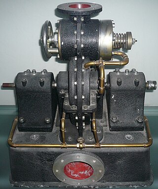
The Tesla turbine is a bladeless centripetal flow turbine invented by Nikola Tesla in 1913. Nozzles apply a moving fluid to the edges of a set of discs. The engine uses smooth discs rotating in a chamber to generate rotational movement due to the momentum exchange between the fluid and the discs. The discs are arranged in an orientation similar to a stack of CDs on a pole.

<span class="mw-page-title-main">Centrifugal compressor</span> Sub-class of dynamic axisymmetric work-absorbing turbomachinery

Centrifugal compressors, sometimes called impeller compressors or radial compressors, are a sub-class of dynamic axisymmetric work-absorbing turbomachinery.

<span class="mw-page-title-main">Compressor</span> Machine to increase pressure of gas by reducing its volume

A compressor is a mechanical device that increases the pressure of a gas by reducing its volume. An air compressor is a specific type of gas compressor.

<span class="mw-page-title-main">Impeller</span> Rotor used to increase (or decrease in case of turbines) the pressure and flow of a fluid or gas

An impeller, or impellor, is a driven rotor used to increase the pressure and flow of a fluid. It is the opposite of a turbine, which extracts energy from, and reduces the pressure of, a flowing fluid.

<span class="mw-page-title-main">Axial compressor</span> Machine for continuous flow gas compression

An axial compressor is a gas compressor that can continuously pressurize gases. It is a rotating, airfoil-based compressor in which the gas or working fluid principally flows parallel to the axis of rotation, or axially. This differs from other rotating compressors such as centrifugal compressor, axi-centrifugal compressors and mixed-flow compressors where the fluid flow will include a "radial component" through the compressor.

<span class="mw-page-title-main">Axial-flow pump</span> Type of pump consisting of a propeller in a pipe

An axial-flow pump, or AFP, is a common type of pump that essentially consists of a propeller in a pipe. The propeller can be driven directly by a sealed motor in the pipe or by electric motor or petrol/diesel engines mounted to the pipe from the outside or by a right-angle drive shaft that pierces the pipe.

A compressor map is a chart which shows the performance of a turbomachinery compressor. This type of compressor is used in gas turbine engines, for supercharging reciprocating engines and for industrial processes, where it is known as a dynamic compressor. A map is created from compressor rig test results or predicted by a special computer program. Alternatively the map of a similar compressor can be suitably scaled. This article is an overview of compressor maps and their different applications and also has detailed explanations of maps for a fan and intermediate and high-pressure compressors from a three-shaft aero-engine as specific examples.

A jet engine performs by converting fuel into thrust. How well it performs is an indication of what proportion of its fuel goes to waste. It transfers heat from burning fuel to air passing through the engine. In doing so it produces thrust work when propelling a vehicle but a lot of the fuel is wasted and only appears as heat. Propulsion engineers aim to minimize the degradation of fuel energy into unusable thermal energy. Increased emphasis on performance improvements for commercial airliners came in the 1970s from the rising cost of fuel.

<span class="mw-page-title-main">Gas turbine engine compressors</span> Engine component

As the name suggests, gas turbine engine compressors provide the compression part of the gas turbine engine thermodynamic cycle. There are three basic categories of gas turbine engine compressor: axial compressor, centrifugal compressor and mixed flow compressor. A fourth, unusual, type is the free-piston gas generator, which combines the functions of compressor and combustion chamber in one unit.

<span class="mw-page-title-main">Centrifugal fan</span> Mechanical fan that forces fluid to move radially outward

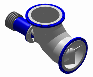
A centrifugal fan is a mechanical device for moving air or other gases in a direction at an angle to the incoming fluid. Centrifugal fans often contain a ducted housing to direct outgoing air in a specific direction or across a heat sink; such a fan is also called a blower, blower fan, or squirrel-cage fan. Tiny ones used in computers are sometimes called biscuit blowers. These fans move air from the rotating inlet of the fan to an outlet. They are typically used in ducted applications to either draw air through ductwork/heat exchanger, or push air through similar impellers. Compared to standard axial fans, they can provide similar air movement from a smaller fan package, and overcome higher resistance in air streams.

<span class="mw-page-title-main">Radial turbine</span> Type of turbine

A radial turbine is a turbine in which the flow of the working fluid is radial to the shaft. The difference between axial and radial turbines consists in the way the fluid flows through the components. Whereas for an axial turbine the rotor is 'impacted' by the fluid flow, for a radial turbine, the flow is smoothly orientated perpendicular to the rotation axis, and it drives the turbine in the same way water drives a watermill. The result is less mechanical stress which enables a radial turbine to be simpler, more robust, and more efficient when compared to axial turbines. When it comes to high power ranges the radial turbine is no longer competitive and the efficiency becomes similar to that of the axial turbines.

In fluid dynamics, flow can be decomposed into primary flow plus secondary flow, a relatively weaker flow pattern superimposed on the stronger primary flow pattern. The primary flow is often chosen to be an exact solution to simplified or approximated governing equations, such as potential flow around a wing or geostrophic current or wind on the rotating Earth. In that case, the secondary flow usefully spotlights the effects of complicated real-world terms neglected in those approximated equations. For instance, the consequences of viscosity are spotlighted by secondary flow in the viscous boundary layer, resolving the tea leaf paradox. As another example, if the primary flow is taken to be a balanced flow approximation with net force equated to zero, then the secondary circulation helps spotlight acceleration due to the mild imbalance of forces. A smallness assumption about secondary flow also facilitates linearization.

Cheng Xu is a Chinese American aerodynamic design engineer and engineering manager. He is a Fellow of the American Society of Mechanical Engineers and a member of the Technical Committee on Energy and Power Systems, IASTED. He also served as a guest editor of International Journal of Rotating Machinery.

In turbomachinery, degree of reaction or reaction ratio (R) is defined as the ratio of the static pressure rise in the rotating blades of a compressor (or drop in turbine blades) to the static pressure rise in the compressor stage (or drop in a turbine stage). Alternatively it is the ratio of static enthalpy change in the rotor to the static enthalpy change in the stage.

Francis turbine converts energy at high pressure heads which are not easily available and hence a turbine was required to convert the energy at low pressure heads, given that the quantity of water was large enough. It was easy to convert high pressure heads to power easily but difficult to do so for low pressure heads. Therefore, an evolution took place that converted the Francis turbine to Kaplan turbine, which generated power at even low pressure heads efficiently.

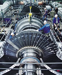
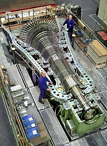
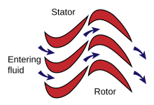
An axial turbine is a turbine in which the flow of the working fluid is parallel to the shaft, as opposed to radial turbines, where the fluid runs around a shaft, as in a watermill. An axial turbine has a similar construction as an axial compressor, but it operates in the reverse, converting flow of the fluid into rotating mechanical energy.

Three-dimension losses and correlation in turbomachinery refers to the measurement of flow-fields in three dimensions, where measuring the loss of smoothness of flow, and resulting inefficiencies, becomes difficult, unlike two-dimensional losses where mathematical complexity is substantially less.

Radial means that the fluid is flowing in radial direction that is either from inward to outward or from outward to inward, with respect to the runner shaft axis. If the fluid is flowing from inward to outward then it is called outflow radial turbine.

  1. In this turbine, the working fluid enters around the axis of the wheel and then flows outwards.
  2. The guide vane mechanism is typically surrounded by the runner/turbine.
  3. In this turbine, the inner diameter of the runner is the inlet and outer diameter is an outlet.

References

  1. 1 2 3 4 5 6 7 8 9 Logan, Earl. "Handbook of turbomachinery". 1995. Marcel Deckker.
  2. 1 2 3 4 5 6 Vandad Talimi (Original author unknown). "Mechanical Equipment and Systems". 2013. Memorial University of Newfoundland. http://www.engr.mun.ca/~yuri/Courses/MechanicalSystems/Turbomachinery.pdf
  3. Çengel, Yunus A.; Cimbala, John M. (2006). Fluid mechanics: fundamentals and applications. McGraw-Hill series in mechanical engineering. Boston, Mass.: McGraw-Hill Higher Education. p. 735. ISBN   978-0-07-247236-3.
  4. "How electricity is generated - U.S. Energy Information Administration (EIA)". www.eia.gov. Retrieved 2023-08-06.
  5. 1 2 Baskharone, E. A. "Principles of Turbomachinery in Air-Breathing Engines". 2006. Cambridge University Press. 580 pages.
  6. Rajadurai, J. S. "Thermodynamics and thermal engineering". 2003. New Age International. ISBN   81-224-1493-1
  7. "Combining Support Vector Machines and Segmentation Algorithms for Efficient Anomaly Detection: A Petroleum Industry Application". International Joint Conference SOCO’14-CISIS’14-ICEUTE’14. 2014. pp.269-278. ISBN   978-3-319-07995-0
  8. Wills, J. George. "Lubrication fundamentals". 1980. Mobil oil corporation. Marcel Dekker. 460 pages. ISBN   0-8247-6976-7
  9. 1 2 3 4 Dixon, S. L. "Fluid mechanics and thermodynamics of turbomachinery". 1998. Elsevier. 460 pages. ISBN   0-7506-7870-4
  10. "Waterjet drives propulsion systems". www.castoldijet.it. Retrieved 2017-10-12.
  11. "WaterJet Overview". HamiltonJet. 2015-03-18. Retrieved 2017-10-12.

Sources