Valve actuator

Last updated
Electric actuator (blue cylinder) on a valve in a power plant. A black handwheel is visible on the actuator, which allows manual positioning of the valve. The blue valve body is visible in-line with the pipe. The valve actuator opens or closes the butterfly disc of the valve based on electrical signals sent to the actuator. Another valve actuator is visible in the background, with windows to indicate the valve position. Power plant a.jpg
Electric actuator (blue cylinder) on a valve in a power plant. A black handwheel is visible on the actuator, which allows manual positioning of the valve. The blue valve body is visible in-line with the pipe. The valve actuator opens or closes the butterfly disc of the valve based on electrical signals sent to the actuator. Another valve actuator is visible in the background, with windows to indicate the valve position.

A valve actuator is the mechanism for opening and closing a valve. Manually operated valves require someone in attendance to adjust them using a direct or geared mechanism attached to the valve stem. Power-operated actuators, using gas pressure, hydraulic pressure or electricity, allow a valve to be adjusted remotely, or allow rapid operation of large valves. Power-operated valve actuators may be the final elements of an automatic control loop which automatically regulates some flow, level or other process. Actuators may be only to open and close the valve, or may allow intermediate positioning; some valve actuators include switches or other ways to remotely indicate the position of the valve.

Contents

Used for the automation of industrial valves, actuators can be found in all kinds of process plants. They are used in waste water treatment plants, power plants, refineries, mining and nuclear processes, food factories, and pipelines. Valve actuators play a major part in automating process control. The valves to be automated vary both in design and dimension. The diameters of the valves range from one-tenth of an inch to several feet.

Types

The common types of actuators are: manual, pneumatic, hydraulic, electric and spring.

Manual

A manual actuator employs levers, gears, or wheels to move the valve stem with a certain action. Manual actuators are powered by hand. Manual actuators are inexpensive, typically self-contained, and easy to operate by humans. However, some large valves are impossible to operate manually and some valves may be located in remote, toxic, or hostile environments that prevent manual operations in some conditions. As a safety feature, certain types of situations may require quicker operation than manual actuators can provide to close the valve.

Pneumatic

Air (or other gas) pressure is the power source for pneumatic valve actuators. [1] They are used on linear or quarter-turn valves. Air pressure acts on a piston or bellows diaphragm creating linear force on a valve stem. Alternatively, a quarter-turn vane-type actuator produces torque to provide rotary motion to operate a quarter-turn valve. A pneumatic actuator may be arranged to be spring-closed or spring-opened, with air pressure overcoming the spring to provide movement. A "double acting" actuator use air applied to different inlets to move the valve in the opening or closing direction. A central compressed air system can provide the clean, dry, compressed air needed for pneumatic actuators. In some types, for example, regulators for compressed gas, the supply pressure is provided from the process gas stream and waste gas either vented to air or dumped into lower-pressure process piping.

Hydraulic

Hydraulic actuators convert fluid pressure into motion. Similar to pneumatic actuators, they are used on linear or quarter-turn valves. Fluid pressure acting on a piston provides linear thrust for gate or globe valves. A quarter-turn actuator produces torque to provide rotary motion to operate a quarter-turn valve. Most types of hydraulic actuators can be supplied with fail-safe features to close or open a valve under emergency circumstances. Hydraulic pressure can be supplied by a self-contained hydraulic pressure pump. In some applications, such as water pumping stations, the process fluid can provide hydraulic pressure, although the actuators must use materials compatible with the fluid.

Electric valve actuator mounted on a pressure reducing needle valve. Electric valve actuator.jpg
Electric valve actuator mounted on a pressure reducing needle valve.

Electric

The electric actuator uses an electric motor to provide torque to operate a valve. They are quiet, non-toxic and energy efficient. However, electricity must be available, which is not always the case, they can also operate on batteries.

Spring

Spring-based actuators hold back a spring. Once any anomaly is detected, or power is lost, the spring is released, operating the valve. They can only operate once, without resetting, and so are used for one-use purposes such as emergencies. They have the advantage that they do not require a powerful electric supply to move the valve, so they can operate from restricted battery power, or automatically when all power has been lost.

Actuator movement

Gate Valve with Handwheel (L) and with Linear Pneumatic Actuator (R) Gate Valve with Handwheel (L) and with Linear Pneumatic Actuator (R).jpg
Gate Valve with Handwheel (L) and with Linear Pneumatic Actuator (R)

A linear actuator opens and closes valves that can be operated via linear force, the type sometimes called a "rising stem" valve. These types of valves include globe valves, rising stem ball valves, control valves and gate valves. [2] The two main types of linear actuators are diaphragm and piston.

Diaphragm actuators are made out of a round piece of rubber and squeezed around its edges between two side of a cylinder or chamber that allows air pressure to enter either side pushing the piece of rubber one direction or the other. A rod is connected to the center of the diaphragm so that it moves as the pressure is applied. The rod is then connected to a valve stem which allows the valve to experience the linear motion thereby opening or closing. A diaphragm actuator is useful if the supply pressure is moderate and the valve travel and thrust required are low.

Piston actuators use a piston which moves along the length of a cylinder. The piston rod conveys the force on the piston to the valve stem. Piston actuators allow higher pressures, longer travel ranges, and higher thrust forces than diaphragm actuators.

A spring is used to provide defined behavior in the case of loss of power. This is important in safety related incidents and is sometimes the driving factor in specifications. An example of loss of power is when the air compressor (the main source of compressed air that provides the fluid for the actuator to move) shuts down. If there is a spring inside of the actuator, it will force the valve open or closed and will keep it in that position while power is restored. An actuator may be specified "fail open" or "fail close" to describe its behavior. In the case of an electric actuator, losing power will keep the valve stationary unless there is a backup power supply.

A typical representative of the valves to be automated is a plug-type control valve. Just like the plug in the bathtub is pressed into the drain, the plug is pressed into the plug seat by a stroke movement. The pressure of the medium acts upon the plug while the thrust unit has to provide the same amount of thrust to be able to hold and move the plug against this pressure.

Features of an electric actuator

CAD modelled cross-section of an assembly of an electric multi-turn actuator with both manual and remote controls. Schnittbild drehnatrieb 01.jpg
CAD modelled cross-section of an assembly of an electric multi-turn actuator with both manual and remote controls.

Motor (1)

Robust asynchronous three-phase AC motors are mostly used as the driving force, for some applications also single-phase AC or DC motors are used. These motors are specially adapted for valve automation as they provide higher torques from standstill than comparable conventional motors, a necessary requirement to unseat sticky valves. The actuators are expected to operate under extreme ambient conditions, however they are generally not used for continuous operation since the motor heat buildup can be excessive.

Limit and torque sensors (2)

The limit switches signal when an end position has been reached. The torque switching measures the torque present in the valve. When exceeding a set limit, this is signaled in the same way. Actuators are often equipped with a remote position transmitter which indicates the valve position as continuous 4-20mA current or voltage signal.

Gearing (3)

Often a worm gearing is used to reduce the high output speed of the electric motor. This enables a high reduction ratio within the gear stage, leading to a low efficiency which is desired for the actuators. The gearing is therefore self-locking i.e. it prevents accidental and undesired changes of the valve position by acting upon the valve’s closing element.

Valve attachment (4)

The valve attachment consists of two elements. First: The flange used to firmly connect the actuator to the counterpart on the valve side. The higher the torque to be transmitted, the larger the flange required.

Second: The output drive type used to transmit the torque or the thrust from the actuator to the valve shaft. Just like there is a multitude of valves there is also a multitude of valve attachments.

Dimensions and design of valve mounting flange and valve attachments are stipulated in the standards EN ISO 5210 for multi-turn actuators or EN ISO 5211 for part-turn actuators. The design of valve attachments for linear actuators is generally based on DIN 3358.

Manual operation (5)

In their basic version most electric actuators are equipped with a handwheel for operating the actuators during commissioning or power failure. The handwheel does not move during motor operation.

The electronic torque limiting switches are not functional during manual operation. Mechanical torque-limiting devices are commonly used to prevent torque overload during manual operation.

Actuator controls (6)

Both actuator signals and operation commands of the DCS are processed within the actuator controls. This task can in principle be assumed by external controls, e.g. a PLC. Modern actuators include integral controls which process signals locally without any delay. The controls also include the switchgear required to control the electric motor. This can either be reversing contactors or thyristors which, being an electric component, are not subject to mechanic wear. Controls use the switchgear to switch the electric motor on or off depending on the signals or commands present. Another task of the actuator controls is to provide the DCS with feedback signals, e.g. when reaching a valve end position.

Electrical connection (7)

The supply cables of the motor and the signal cables for transmitting the commands to the actuator and sending feedback signals on the actuator status are connected to the electrical connection. The electrical connection can be designed as a separately sealed terminal bung or plug/socket connector. For maintenance purposes, the wiring should be easily disconnected and reconnected.

Fieldbus connection (8)

Fieldbus technology is increasingly used for data transmission in process automation applications. Electric actuators can therefore be equipped with all common fieldbus interfaces used in process automation. Special connections are required for the connection of fieldbus data cables.

Functions

Automatic switching off in the end positions

After receiving an operation command, the actuator moves the valve in direction OPEN or CLOSE. When reaching the end position, an automatic switch-off procedure is started. Two fundamentally different switch-off mechanisms can be used. The controls switch off the actuator as soon as the set tripping point has been reached. This is called limit seating. However, there are valve types for which the closing element has to be moved in the end position at a defined force or a defined torque to ensure that the valve seals tightly. This is called torque seating. The controls are programmed as to ensure that the actuator is switched off when exceeding the set torque limit. The end position is signalled by a limit switch.

Safety functions

The torque switching is not only used for torque seating in the end position, but it also serves as overload protection over the whole travel and protects the valve against excessive torque. If excessive torque acts upon the closing element in an intermediate position, e.g. due to a trapped object, the torque switching will trip when reaching the set tripping torque. In this situation the end position is not signalled by the limit switch. The controls can therefore distinguish between normal operation torque switch tripping in one of the end positions and switching off in an intermediate position due to excessive torque.

Temperature sensors are required to protect the motor against overheating. For some applications by other manufacturers, the increase of the motor current is also monitored. Thermoswitches or PTC thermistors which are embedded in the motor windings mostly reliably fulfil this task. They trip when the temperature limit has been exceeded and the controls switch off the motor.

The positioner [1] is supplied with a setpoint [2] and an actual value [3]. The motor is controlled until the actual value is identical to the setpoint. The DCS generally needs a feedback signal [4] Actuator positioner.jpg
The positioner [1] is supplied with a setpoint [2] and an actual value [3]. The motor is controlled until the actual value is identical to the setpoint. The DCS generally needs a feedback signal [4]

Process control functions

Due to increasing decentralisation in automation technology and the introduction of micro processors, more and more functions have been transferred from the DCS to the field devices. The data volume to be transmitted was reduced accordingly, in particular by the introduction of fieldbus technology. Electric actuators whose functions have been considerably expanded are also affected by this development. The simplest example is the position control. Modern positioners are equipped with self-adaptation i.e. the positioning behaviour is monitored and continuously optimised via controller parameters.

Meanwhile, electric actuators are equipped with fully-fledged process controllers (PID controllers). Especially for remote installations, e.g. the flow control to an elevated tank, the actuator can assume the tasks of a PLC which otherwise would have to be additionally installed.

Diagnosis

Modern actuators have extensive diagnostic functions which can help identify the cause of a failure. They also log the operating data. Study of the logged data allows the operation to be optimised by changing the parameters and the wear of both actuator and valve to be reduced.

Duty types

Typical time period in open-close duty. t1 is the operating time and may not exceed the maximum permissible running time Charakteristics open close duty.jpg
Typical time period in open-close duty. t1 is the operating time and may not exceed the maximum permissible running time
Typical time period in modulating duty. Charakteristics modulating duty.jpg
Typical time period in modulating duty.

Open-close duty

If a valve is used as a shut-off valve, then it will be either open or closed and intermediate positions are not held...

Positioning duty

Defined intermediate positions are approached for setting a static flow through a pipeline. The same running time limits as in open-close duty apply.

Modulating duty

The most distinctive feature of a closed-loop application is that changing conditions require frequent adjustment of the actuator, for example, to set a certain flow rate. Sensitive closed-loop applications require adjustments within intervals of a few seconds. The demands on the actuator are higher than in open-close or positioning duty. Actuator design must be able to withstand the high number of starts without any deterioration in control accuracy.

Service conditions

Actuators have to work in different weather conditions like low or high temperatures. Actuator siberia.jpg
Actuators have to work in different weather conditions like low or high temperatures.
Actuators on top of a dam. Actuator sahara.JPG
Actuators on top of a dam.

Actuators are specified for the desired life and reliability for a given set of application service conditions. In addition to the static and dynamic load and response time required for the valve, the actuator must withstand the temperature range, corrosion environment and other conditions of a specific application. Valve actuator applications are often safety related, therefore the plant operators put high demands on the reliability of the devices. Failure of an actuator may cause accidents in process-controlled plants and toxic substances may leak into the environment.

Process-control plants are often operated for several decades which justifies the higher demands put on the lifetime of the devices.

For this reason, actuators are always designed in high enclosure protection. The manufacturers put a lot of work and knowledge into corrosion protection.

Enclosure protection

The enclosure protection types are defined according to the IP codes of EN 60529. The basic versions of most electric actuators are designed to the second highest enclosure protection IP 67. This means they are protected against the ingress of dust and water during immersion (30 min at a max. head of water of 1 m). Most actuator manufacturers also supply devices to enclosure protection IP 68 which provides protection against submersion up to a max. head of water of 6 m.

Ambient temperatures

In Siberia, temperatures down to – 60 °C may occur, and in technical process plants + 100 °C may be exceeded. Using the proper lubricant is crucial for full operation under these conditions. Greases which may be used at room temperature can become too solid at low temperatures for the actuator to overcome the resistance within the device. At high temperatures, these greases can liquify and lose their lubricating power. When sizing the actuator, the ambient temperature and the selection of the correct lubricant are of major importance.

Explosion protection

Actuators are used in applications where potentially explosive atmospheres may occur. This includes among others refineries, pipelines, oil and gas exploration or even mining. When a potentially explosive gas-air-mixture or gas-dust-mixture occurs, the actuator must not act as ignition source. Hot surfaces on the actuator as well as ignition sparks created by the actuator have to be avoided. This can be achieved by a flameproof enclosure, where the housing is designed to prevent ignition sparks from leaving the housing even if there is an explosion inside.

Actuators designed for these applications, being explosion-proof devices, have to be qualified by a test authority (notified body). Explosion protection is not standardized worldwide. Within the European Union, ATEX 94/9/EC applies, in US, the NEC (approval by FM) or the CEC in Canada (approval by the CSA). Explosion-proof actuators have to meet the design requirements of these directives and regulations.

Additional uses

Small electric actuators can be used in a wide variety of assembly, packaging and testing applications. Such actuators can be linear, rotary, or a combination of the two, and can be combined to perform work in three dimensions. Such actuators are often used to replace pneumatic cylinders. [4]

Related Research Articles

<span class="mw-page-title-main">Valve</span> Flow control device

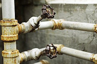
A valve is a device or natural object that regulates, directs or controls the flow of a fluid by opening, closing, or partially obstructing various passageways. Valves are technically fittings, but are usually discussed as a separate category. In an open valve, fluid flows in a direction from higher pressure to lower pressure. The word is derived from the Latin valva, the moving part of a door, in turn from volvere, to turn, roll.

A transducer is a device that converts energy from one form to another. Usually a transducer converts a signal in one form of energy to a signal in another. Transducers are often employed at the boundaries of automation, measurement, and control systems, where electrical signals are converted to and from other physical quantities. The process of converting one form of energy to another is known as transduction.

<span class="mw-page-title-main">Rack and pinion</span> Type of linear actuator

A rack and pinion is a type of linear actuator that comprises a circular gear engaging a linear gear. Together, they convert between rotational motion and linear motion. Rotating the pinion causes the rack to be driven in a line. Conversely, moving the rack linearly will cause the pinion to rotate. A rack-and-pinion drive can use both straight and helical gears. Though some suggest helical gears are quieter in operation, no hard evidence supports this theory. Helical racks, while being more affordable, have proven to increase side torque on the datums, increasing operating temperature leading to premature wear. Straight racks require a lower driving force and offer increased torque and speed per fraction of gear ratio which allows lower operating temperature and lessens viscal friction and energy use. The maximum force that can be transmitted in a rack-and-pinion mechanism is determined by the torque on the pinion and its size, or, conversely, by the force on the rack and the size of the pinion.

An actuator is a component of a machine that produces force, torque, or displacement, usually in a controlled way, when an electrical, pneumatic or hydraulic input is supplied to it in a system. An actuator converts such an input signal into the required form of mechanical energy. It is a type of transducer. In simple terms, it is a "mover".

<span class="mw-page-title-main">Fluid power</span> Use of fluids under pressure to generate, control, and transmit power

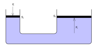
Fluid power is the use of fluids under pressure to generate, control, and transmit power. Fluid power is conventionally subdivided into hydraulics and pneumatics. Although steam is also a fluid, steam power is usually classified separately from fluid power. Compressed-air and water-pressure systems were once used to transmit power from a central source to industrial users over extended geographic areas; fluid power systems today are usually within a single building or mobile machine.

<span class="mw-page-title-main">Hydraulic machinery</span> Type of machine that uses liquid fluid power to perform work

Hydraulic machines use liquid fluid power to perform work. Heavy construction vehicles are a common example. In this type of machine, hydraulic fluid is pumped to various hydraulic motors and hydraulic cylinders throughout the machine and becomes pressurized according to the resistance present. The fluid is controlled directly or automatically by control valves and distributed through hoses, tubes, or pipes.

Power steering is a system for reducing a driver's effort to turn a steering wheel of a motor vehicle, by using a power source to assist steering.

<span class="mw-page-title-main">Pneumatic motor</span> Compressed-air engine

A pneumatic motor, or compressed-air engine, is a type of motor which does mechanical work by expanding compressed air. Pneumatic motors generally convert the compressed-air energy to mechanical work through either linear or rotary motion. Linear motion can come from either a diaphragm or piston actuator, while rotary motion is supplied by either a vane type air motor, piston air motor, air turbine or gear type motor.

<span class="mw-page-title-main">Damper (flow)</span> Valve or plate for regulating airflow inside a duct, chimney, vent, etc.

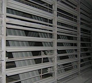
A damper is a valve or plate that stops or regulates the flow of air inside a duct, chimney, VAV box, air handler, or other air-handling equipment. A damper may be used to cut off central air conditioning to an unused room, or to regulate it for room-by-room temperature and climate control - for example, in the case of Volume Control Dampers. Its operation can be manual or automatic. Manual dampers are turned by a handle on the outside of a duct. Automatic dampers are used to regulate airflow constantly and are operated by electric or pneumatic motors, in turn controlled by a thermostat or building automation system. Automatic or motorized dampers may also be controlled by a solenoid, and the degree of air-flow calibrated, perhaps according to signals from the thermostat going to the actuator of the damper in order to modulate the flow of air-conditioned air in order to effect climate control.

<span class="mw-page-title-main">Solenoid valve</span> Electromechanical valve

A solenoid valve is an electromechanically operated valve.

<span class="mw-page-title-main">Linear actuator</span> Actuator that creates motion in a straight line

A linear actuator is an actuator that creates linear motion, in contrast to the circular motion of a conventional electric motor. Linear actuators are used in machine tools and industrial machinery, in computer peripherals such as disk drives and printers, in valves and dampers, and in many other places where linear motion is required. Hydraulic or pneumatic cylinders inherently produce linear motion. Many other mechanisms are used to generate linear motion from a rotating motor.

A pneumatic control valve actuator converts energy into mechanical motion. The motion can be rotary or linear, depending on the type of actuator.

A transmission control unit (TCU), also known as a transmission control module (TCM), or a gearbox control unit (GCU), is a type of automotive ECU that is used to control electronic automatic transmissions. Similar systems are used in conjunction with various semi-automatic transmissions, purely for clutch automation and actuation. A TCU in a modern automatic transmission generally uses sensors from the vehicle, as well as data provided by the engine control unit (ECU), to calculate how and when to change gears in the vehicle for optimum performance, fuel economy and shift quality.

<span class="mw-page-title-main">Diaphragm valve</span> Flow control device

Diaphragm valves consists of a valve body with two or more ports, a flexible diaphragm, and a "weir or saddle" or seat upon which the diaphragm closes the valve. The valve body may be constructed from plastic, metal, wood or other materials depending on the intended use.

<span class="mw-page-title-main">Pressure switch</span> Form of switch that operates an electrical contact

A pressure switch is a form of switch that operates an electrical contact when a certain set fluid pressure has been reached on its input. The switch may be designed to make contact either on pressure rise or on pressure fall. Pressure switches are widely used in industry to automatically supervise and control systems that use pressurized fluids.

A control valve is a valve used to control fluid flow by varying the size of the flow passage as directed by a signal from a controller. This enables the direct control of flow rate and the consequential control of process quantities such as pressure, temperature, and liquid level.

A shutdown valve is an actuated valve designed to stop the flow of a hazardous fluid upon the detection of a dangerous event. This provides protection against possible harm to people, equipment or the environment. Shutdown valves form part of a safety instrumented system. The process of providing automated safety protection upon the detection of a hazardous event is called functional safety.

An electrohydraulic servo valve (EHSV) is an electrically-operated valve that controls how hydraulic fluid is sent to an actuator. Servo valves are often used to control powerful hydraulic cylinders with a very small electrical signal. Servo valves can provide precise control of position, velocity, pressure, and force with good post-movement damping characteristics.

<span class="mw-page-title-main">Rotary actuator</span> AE motor

A rotary actuator is an actuator that produces a rotary motion or torque.

In engineering, a solenoid is a device that converts electrical energy to mechanical energy, using an electromagnet formed from a coil of wire. The device creates a magnetic field from electric current, and uses the magnetic field to create linear motion. In electromagnetic technology, a solenoid is an actuator assembly with a sliding ferromagnetic plunger inside the coil. Without power, the plunger extends for part of its length outside the coil; applying power pulls the plunger into the coil. Electromagnets with fixed cores are not considered solenoids. In simple terms, a solenoid converts electrical energy into mechanical work. Typically, it has a multiturn coil of magnet wire surrounded by a frame, which is also a magnetic flux carrier to enhance its efficiency. In engineering, the term may also refer to a variety of transducer devices that convert energy into linear motion, more sophisticated than simple two–position actuators. The term "solenoid" also often refers to a solenoid valve, an integrated device containing an electromechanical solenoid which actuates either a pneumatic or hydraulic valve, or a solenoid switch, which is a specific type of relay that internally uses an electromechanical solenoid to operate an electrical switch; for example, an automobile starter solenoid or linear solenoid. Solenoid bolts, a type of electromechanical locking mechanism, also exist.

References

  1. "Blog - La Fox, Illinois-BI-TORQ Valve Automation". www.bitorq.com. Retrieved 2018-08-28.
  2. Etheridge, Cooper (June 2014). "For Gate Valves, Actuation is not Turn Turn Turn". Valve World Americas (5): 6.
  3. Baumann, Oliver "Type of documents/Cut-away drawings/Actuators Archived 2013-05-15 at the Wayback Machine ". AUMA Riester GmbH & Co. KG. September 28, 2008.
  4. Preston, David. "Actuator drawings and catalogs"