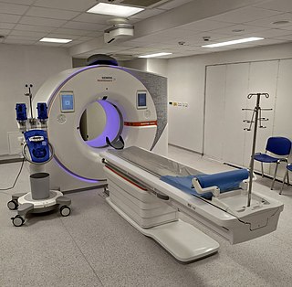
A computed tomography scan, formerly called computed axial tomography scan, is a medical imaging technique used to obtain detailed internal images of the body. The personnel that perform CT scans are called radiographers or radiology technologists. CT scanners use a rotating X-ray tube and a row of detectors placed in a gantry to measure X-ray attenuations by different tissues inside the body. The multiple X-ray measurements taken from different angles are then processed on a computer using tomographic reconstruction algorithms to produce tomographic (cross-sectional) images of a body. CT scans can be used in patients with metallic implants or pacemakers, for whom magnetic resonance imaging (MRI) is contraindicated.
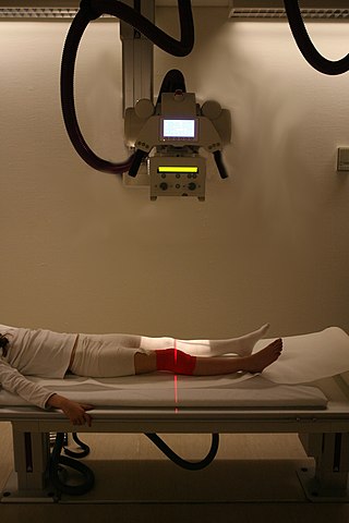
Radiography is an imaging technique using X-rays, gamma rays, or similar ionizing radiation and non-ionizing radiation to view the internal form of an object. Applications of radiography include medical and industrial radiography. Similar techniques are used in airport security,. To create an image in conventional radiography, a beam of X-rays is produced by an X-ray generator and it is projected towards the object. A certain amount of the X-rays or other radiation are absorbed by the object, dependent on the object's density and structural composition. The X-rays that pass through the object are captured behind the object by a detector. The generation of flat two-dimensional images by this technique is called projectional radiography. In computed tomography, an X-ray source and its associated detectors rotate around the subject, which itself moves through the conical X-ray beam produced. Any given point within the subject is crossed from many directions by many different beams at different times. Information regarding the attenuation of these beams is collated and subjected to computation to generate two-dimensional images on three planes which can be further processed to produce a three-dimensional image.

Agilent Technologies, Inc. is an American global company headquartered in Santa Clara, California, that provides instruments, software, services, and consumables for laboratories. Agilent was established in 1999 as a spin-off from Hewlett-Packard. The resulting IPO of Agilent stock was the largest in the history of Silicon Valley at the time. From 1999 to 2014, the company produced optics, semiconductors, EDA software and test and measurement equipment for electronics; that division was spun off to form Keysight. Since then, the company has continued to expand into pharmaceutical, diagnostics & clinical, and academia & government (research) markets.

Tomography is imaging by sections or sectioning that uses any kind of penetrating wave. The method is used in radiology, archaeology, biology, atmospheric science, geophysics, oceanography, plasma physics, materials science, cosmochemistry, astrophysics, quantum information, and other areas of science. The word tomography is derived from Ancient Greek τόμος tomos, "slice, section" and γράφω graphō, "to write" or, in this context as well, "to describe." A device used in tomography is called a tomograph, while the image produced is a tomogram.

Electron beam computed tomography (EBCT) is a fifth generation computed tomography (CT) scanner in which the X-ray tube is not mechanically spun in order to rotate the source of X-ray photons. This different design was explicitly developed to better image heart structures that never stop moving, performing a complete cycle of movement with each heartbeat.

In radiography, X-ray microtomography uses X-rays to create cross-sections of a physical object that can be used to recreate a virtual model without destroying the original object. It is similar to tomography and X-ray computed tomography. The prefix micro- is used to indicate that the pixel sizes of the cross-sections are in the micrometre range. These pixel sizes have also resulted in creation of its synonyms high-resolution X-ray tomography, micro-computed tomography, and similar terms. Sometimes the terms high-resolution computed tomography (HRCT) and micro-CT are differentiated, but in other cases the term high-resolution micro-CT is used. Virtually all tomography today is computed tomography.
In microtomography X-ray scanners, cone beam reconstruction is one of two common scanning methods, the other being Fan beam reconstruction.
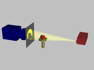
A fiducial marker or fiducial is an object placed in the field of view of an image for use as a point of reference or a measure. It may be either something placed into or on the imaging subject, or a mark or set of marks in the reticle of an optical instrument.
The CTX is an explosive detection device, a family of x-ray devices developed by InVision Technologies in 1990 that uses CAT scans and sophisticated image processing software to automatically screen checked baggage for explosives.

Automated optical inspection (AOI) is an automated visual inspection of printed circuit board (PCB) manufacture where a camera autonomously scans the device under test for both catastrophic failure and quality defects. It is commonly used in the manufacturing process because it is a non-contact test method. It is implemented at many stages through the manufacturing process including bare board inspection, solder paste inspection (SPI), pre-reflow and post-re-flow as well as other stages.
Bernard Marshall Gordon is an American engineer, inventor, entrepreneur, and philanthropist. He is considered "the father of high-speed analog-to-digital conversion".
Terahertz tomography is a class of tomography where sectional imaging is done by terahertz radiation. Terahertz radiation is electromagnetic radiation with a frequency between 0.1 and 10 THz; it falls between radio waves and light waves on the spectrum; it encompasses portions of the millimeter waves and infrared wavelengths. Because of its high frequency and short wavelength, terahertz wave has a high signal-to-noise ratio in the time domain spectrum. Tomography using terahertz radiation can image samples that are opaque in the visible and near-infrared regions of the spectrum. Terahertz wave three-dimensional (3D) imaging technology has developed rapidly since its first successful application in 1997, and a series of new 3D imaging technologies have been proposed successively.
Automated X-ray inspection (AXI) is a technology based on the same principles as automated optical inspection (AOI). It uses X-rays as its source, instead of visible light, to automatically inspect features, which are typically hidden from view.

Tomosynthesis, also digital tomosynthesis (DTS), is a method for performing high-resolution limited-angle tomography at radiation dose levels comparable with projectional radiography. It has been studied for a variety of clinical applications, including vascular imaging, dental imaging, orthopedic imaging, mammographic imaging, musculoskeletal imaging, and chest imaging.
Viscom AG is a manufacturer of inspection technologies, in particular for automatic optical inspection (AOI) and X-ray inspection, with headquarters in Hanover, Germany, used in automotive electronics, entertainment electronics, telecommunications and industrial electronics.
John Fitzallen Moore was an American physicist, the son of authors Virginia Moore and Louis Untermeyer. His last name was legally changed after his parents' divorce. His work in military electronics, communications, and spectroscopy culminated in medical electronics and x-ray products with the founding of the company Bio-Imaging Research.

Industrial computed tomography (CT) scanning is any computer-aided tomographic process, usually X-ray computed tomography, that uses irradiation to produce three-dimensional internal and external representations of a scanned object. Industrial CT scanning has been used in many areas of industry for internal inspection of components. Some of the key uses for industrial CT scanning have been flaw detection, failure analysis, metrology, assembly analysis and reverse engineering applications. Just as in medical imaging, industrial imaging includes both nontomographic radiography and computed tomographic radiography.
Keysight Technologies, Inc. is an American company that manufactures electronics test and measurement equipment and software. The name is a blend of key and insight. The company was formed as a spin-off of Agilent Technologies, which inherited and rebranded the test and measurement product lines developed and produced from the late 1960s to the turn of the millennium by Hewlett-Packard's Test & Measurement division.

X-ray computed tomography operates by using an X-ray generator that rotates around the object; X-ray detectors are positioned on the opposite side of the circle from the X-ray source.
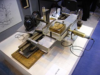
The history of X-ray computed tomography (CT) dates back to at least 1917 with the mathematical theory of the Radon transform. In the early 1900s an Italian radiologist named Alessandro Vallebona invented tomography which used radiographic film to see a single slice of the body. It was not widely used until the 1930s, when Dr Bernard George Ziedses des Plantes developed a practical method for implementing the technique, known as focal plane tomography. It relies on mechanical movement of the X-ray beam source and capture film in unison to ensure that the plane of interest remains in focus with objects falling outside of the plane being examined blurring out.
