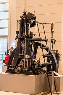
Air-blast injection

Last updated
US patent #432260 Brayton's 1890 4 stroke kerosene fuel air blast engine US432260-Figure1.png
US patent #432260 Brayton's 1890 4 stroke kerosene fuel air blast engine
Lufteinblasflaschen.jpg
Compressed-air tanks
Dieselmotor Langen & Wolf, 1898.jpg
Lateral view
Langen & Wolf Diesel engine using air-blast injection, 1898
Dieselmotor No 561.jpg
Lateral view, compressor and compressed-air tanks well visible
OHC-Ventilsteuerung 1915.jpg
Camshaft and rocker arms seen from above

Air-blast injection is a historical direct injection system for Diesel engines. Unlike modern designs, air-blast injected Diesel engines do not have an injection pump. A simple low-pressure fuel-feed-pump is used instead to supply the injection nozzle with fuel. At injection, a blast of compressed air presses the fuel into the combustion chamber, hence the name air-blast injection. The compressed air comes from compressed-air tanks which feed the injection nozzle. A large crankshaft-driven compressor is used to re-fill these tanks; the size of the compressor and the low rotational frequency of the engine's crankshaft means that air-blast injected Diesel engines are huge in size and mass, this, combined with the problem that air-blast injection does not allow for quick load alteration [1] makes it only suitable for stationary applications and watercraft. Before the invention of precombustion chamber injection, air-blast injection was the only way a properly working internal air fuel mixture system could be built, required for a Diesel engine. During the 1920s, [2] air-blast injection was rendered obsolete by superior injection system designs that allowed much smaller but more powerful engines. [3] Rudolf Diesel was granted a patent on air-blast injection in November 1893 (DRP 82 168). [4]

Contents

History

The air-blast injection system was first used by George Bailey Brayton in 1872 for a gas engine, and in 1890 for a four-stroke kerosene fueled engine. Rudolf Diesel wanted to build an engine with direct injection for which he tried using accumulating in 1893. [5] Due to the highly viscous fuels Diesel used and thermal afterburning occurring, the principle of accumulating did not work sufficiently. Therefore, Diesel had to improve the injection system. German engineer Friedrich Sass says that Diesel knew about Brayton's invention and that it is therefore very likely that Diesel decided to replace his own inferior injection system with an air-blast injection system similar to Brayton's. [6] Diesel did so in February 1894, [4] because he could not come up with a better solution, however, Diesel wanted to replace the air-blast injection system with a superior system ever since; an improved accumulating system which allowed for direct injection without a huge compressor was patented by Diesel and Rudolf Brandstetter in 1905. [7] Nevertheless, this improved system was still insufficient and Diesel considered direct injection without a huge compressor „unfeasible“. It took another ten years for the first working direct injected Diesel engines which were not air-blast injected to show up in 1915; [8] the precombustion chamber, which made motor vehicle Diesel engines possible, had been invented in 1909. [9]

Design

Atomiser design

Initially, sieve-type amtomisers were used for the injections nozzles, until the sieves were widely replaced by discs. [1] Also, ring-type atomisers were used for some engines. [10]

The ring-type atomiser is based on the principle of different air velocities occurring inside the nozzle, which force the fuel to mix up with air. [11] Disc-type atomisers have small perforated discs placed above each other with small gaps in between (as seen in Fig. 6 in the sectional drawing on the right). The discs are slightly misaligned to increase constriction. Depending on the capacity of the engine and, therefore, quantity of injected fuel, either two, three or four dics are used per injection nozzle. The disc material depends on the fuel type. In general, bronze casting and phosphor bronze casting are used; for engines running on coal tar, the discs are usually made from steel. [12]

For engines with disc-type atomisers, the injection pressure should be in sync with the rotational frequency of the crankshaft. This means that with an increase in rotational frequency, the air pressure must be increased as well. [13] Usually, at injection, 97% air and 3% fuel are getting injected through the injection nozzle. [8] The injection pressure is between 5 and 7 MPa which limits the rotational frequency. Also, with increasing engine load, the injection pressure must be reduced to prevent misfire. [13]

Neither disc hole diameter calculation nor the proper size of the discs were known engineering knowledge at the beginning of the 20th Century. The disc designs were usually based on the engineers' experience. While big holes require a lot of compressed air and therefore consume more engine power, holes being too small reduce the engine power output. Julius Magg recommends a disc hole diameter depending on the indicated cylinder power output: . is the hole diameter in millimetres, is the power output in PS. [14]

Nozzle layout

In the early 20th Century, two different injection nozzle designs for air-blast injected engines were common: The open nozzle and the closed nozzle design. [15]

The closed nozzle design was the initial and most common design, it is usually found in vertical engines (such as the Langen & Wolf engine as seen on the right). It can be used for both two- and four-stroke engines. The injection nozzle is supplied with fuel from the fuel-feed-pump while constantly being fed with compressed air from the compressed-air tank. This means that the fuel-feed-pump has to overcome the resistance caused by the injection-air-pressure. A separate cam on the camshaft (as seen in Fig. 5 and on the two-cylinder Johann-Weitzer-engine on the right) would activate the injection valve so the compressed air would then press the fuel into the combustion chamber. Before the injection valve opens, neither fuel nor compressed air can enter the combustion chamber. [16] The closed nozzle design allowed for a good air-fuel-mixture at the time which made it very useful for high capacity engines. This also resulted in lower fuel consumption compared to the open nozzle design. Biggest disadvantages were the higher manufacturing cost and the injection nozzle restrictions that made designing engines with horizontal cylinders considerably difficult, [17] since in horizontal cylinder engines, compressed air can easily enter the cylinder without pressing a sufficient quantity of fuel into the combustion chamber which leads to engine misfire or postignition. [18]

The open nozzle design was mostly used for engines with horizontal cylinders and unusual for engines with vertical cylinders. It can only be used for four-stroke engines. [17] Like in the closed nozzle design, the fuel is fed to the injection nozzle. However, the injection valve only prevents compressed air from entering the cylinder; the fuel constantly enters a prechamber above the combustion chamber in the cylinder. Between prechamber and combustion chamber, the disc-type atomisers are placed to separate the chambers from each other. At injection, the compressed air would then press the fuel through the disc-type atomisers into the combustion chamber. [19] Manufacturing engines featuring the open nozzle design was considerably cheaper and easier than making them with a closed nozzle design. It also allows for using tar as fuel. However, fuel supply is insufficient and at the beginning of the injection, too much fuel enters the combustion chamber which causes too much pressure buildup inside the cylinder. This, as well as the problem that it is impossible to supply high capacity engines sufficiently with fuel, means, that the open nozzle design can only be used for smaller engines. [17]

Related Research Articles

Diesel engine Type of internal combustion engine

The diesel engine, named after Rudolf Diesel, is an internal combustion engine in which ignition of the fuel is caused by the elevated temperature of the air in the cylinder due to mechanical compression; thus, the diesel engine is a so-called compression-ignition engine. This contrasts with engines using spark plug-ignition of the air-fuel mixture, such as a petrol engine or a gas engine.

Fuel injection Feature of internal combustion engine

Fuel injection is the introduction of fuel in an internal combustion engine, most commonly automotive engines, by the means of an injector. This article focuses on fuel injection in reciprocating piston and rotary piston engines.

A stratified charge engine describes a certain type of internal combustion engine, usually spark ignition (SI) engine that can be used in trucks, automobiles, portable and stationary equipment. The term "stratified charge" refers to the working fluids and fuel vapors entering the cylinder. Usually the fuel is injected into the cylinder or enters as a fuel rich vapor where a spark or other means are used to initiate ignition where the fuel rich zone interacts with the air to promote complete combustion. A stratified charge can allow for slightly higher compression ratios without "knock," and leaner air/fuel ratio than in conventional internal combustion engines.

Brayton cycle Thermodynamic cycle

The Brayton cycle is a thermodynamic cycle that describes the operation of certain heat engines that have air or some other gas as their working fluid. The original Brayton engines used a piston compressor and piston expander, but modern gas turbine engines and airbreathing jet engines also follow the Brayton cycle. Although the cycle is usually run as an open system, it is conventionally assumed for the purposes of thermodynamic analysis that the exhaust gases are reused in the intake, enabling analysis as a closed system.

A combustion chamber is part of an internal combustion engine in which the fuel/air mix is burned. For steam engines, the term has also been used for an extension of the firebox which is used to allow a more complete combustion process.

Indirect injection in an internal combustion engine is fuel injection where fuel is not directly injected into the combustion chamber. Gasoline engines equipped with indirect injection systems, wherein a fuel injector delivers the fuel at some point before the intake valve, have mostly fallen out of favor to direct injection. However, certain manufacturers such as Volkswagen, Toyota and Ford have developed a 'dual injection' system, combining direct injectors with port (indirect) injectors, combining the benefits of both types of fuel injection. Direct injection allows the fuel to be precisely metered into the combustion chamber under high pressure which can lead to greater power, fuel efficiency. The issue with direct injection is that it typically leads to greater amounts of particulate matter and with the fuel no longer contacting the intake valves, carbon can accumulate on the intake valves over time. Adding indirect injection keeps fuel spraying on the intake valves, reducing or eliminating the carbon accumulation on intake valves and in low load conditions, indirect injection allows for better fuel-air mixing. This system is mainly used in higher cost models due to the added expense and complexity.

Gasoline direct injection Mixture formation system

Gasoline direct injection (GDI), also known as petrol direct injection (PDI), is a mixture formation system for internal combustion engines that run on gasoline (petrol), where fuel is injected into the combustion chamber. This is distinct from manifold fuel injection systems, which inject fuel into the intake manifold.

Hot-bulb engine Internal combustion engine

The hot-bulb engine is a type of internal combustion engine in which fuel ignites by coming in contact with a red-hot metal surface inside a bulb, followed by the introduction of air (oxygen) compressed into the hot-bulb chamber by the rising piston. There is some ignition when the fuel is introduced, but it quickly uses up the available oxygen in the bulb. Vigorous ignition takes place only when sufficient oxygen is supplied to the hot-bulb chamber on the compression stroke of the engine.
Aprilia SR50

The Aprilia SR50 is a scooter built by Aprilia. Introduced in 1992, more than 800,000 units have been sold, bucking the trend for less use of two-stroke engines. Aprilia claims several firsts for the SR50 in the scooter market, including 13 inch wheels, liquid cooling, double disc braking, and a direct injection engine.

Glowplug Heating element used to aid in starting diesel engines

A glowplug is a heating device used to aid in starting diesel engines. In cold weather, high-speed diesel engines can be difficult to start because the mass of the cylinder block and cylinder head absorb the heat of compression, preventing ignition. Pre-chambered engines use small glowplugs inside the pre-chambers. Direct-injected engines have these glowplugs in the combustion chamber.

Diesel engine runaway is a rare condition affecting diesel engines, in which the engine draws extra fuel from an unintended source and overspeeds at higher and higher RPM, producing up to ten times the engine's rated output until destroyed by mechanical failure or bearing seizure due to a lack of lubrication. Two-stroke hot-bulb engines can also run away via the same process.

Two-stroke diesel engine Engine type

A two-stroke diesel engine is an internal combustion engine that uses compression ignition, with a two-stroke combustion cycle. It was invented by Hugo Güldner in 1899.

Internal combustion engines come in a wide variety of types, but have certain family resemblances, and thus share many common types of components.

Internal combustion engine Engine in which the combustion of a fuel occurs with an oxidizer in a combustion chamber

An internal combustion engine is a heat engine in which the combustion of a fuel occurs with an oxidizer in a combustion chamber that is an integral part of the working fluid flow circuit. In an internal combustion engine, the expansion of the high-temperature and high-pressure gases produced by combustion applies direct force to some component of the engine. The force is applied typically to pistons, turbine blades, a rotor, or a nozzle. This force moves the component over a distance, transforming chemical energy into useful kinetic energy and is used to propel, move or power whatever the engine is attached to. This replaced the external combustion engine for applications where weight or size of the engine is important.

Mercedes-Benz OM 138 Motor vehicle engine

The Mercedes-Benz OM 138 is a diesel engine manufactured by Daimler-Benz. In total, 5,719 units were produced between 1935 and 1940. It was the first diesel engine especially developed and made for a passenger car. The first vehicle powered by the OM 138 was the Mercedes-Benz W 138. The light Mercedes-Benz trucks L 1100 and L 1500 as well as the bus O 1500 were also offered with the OM 138 as an alternative to the standard Otto engine.

Julius Magg was an Austrian engineer and university professor. In the early 20th century, he contributed significantly to the further development of the Diesel engine. Later, he was known as the founder of the Graz method of engine design.

M-System

The MAN M-System, also referred to as M-Process and M combustion process, is a direct injection system for Diesel engines. In M-System engines, the fuel is injected onto the walls of the combustion chamber that is solely located inside the piston, and shaped like a sphere. The M-System was rendered obsolete by modern fuel injection systems for Diesel engines. Due to its particularities, the M-System was only used for stationary applications and commercial vehicle engines, passenger car engines with this design have never been made. The letter M is an abbreviation for the German word Mittenkugelverfahren, meaning centre sphere combustion process.

Manifold injection is a mixture formation system for internal combustion engines with external mixture formation. It is commonly used in engines with spark ignition that use petrol as fuel, such as the Otto engine, and the Wankel engine. In a manifold-injected engine, the fuel is injected into the intake manifold, where it begins forming a combustible air-fuel mixture with the air. As soon as the intake valve opens, the piston starts sucking in the still forming mixture. Usually, this mixture is relatively homogeneous, and, at least in production engines for passenger cars, approximately stoichiometric; this means that there is an even distribution of fuel and air across the combustion chamber, and enough, but not more air present than what is required for the fuel's complete combustion. The injection timing and measuring of the fuel amount can be controlled either mechanically, or electronically. Since the 1970s and 1980s, manifold injection has been replacing carburettors in passenger cars. However, since the late 1990s, car manufacturers have started using petrol direct injection, which caused a decline in manifold injection installation in newly produced cars.

Motor 250/400 Motor vehicle engine

The Motor 250/400 is the first functional diesel engine. It was designed by Rudolf Diesel, and drawn by Imanuel Lauster. The workshop of the Maschinenfabrik Augsburg built two units, the A-Motor, and the B-Motor. The latter has been on static display at the Deutsches Museum in Munich since testing it came to an end. Throughout the late 1890s, several licensed copies of the Motor 250/400 were made. Most of these copies were very unreliable, which almost caused the diesel engine's demise.

Friedrich Sass was a German engineer, university professor and historian.

References

  1. 1 2 Rüdiger Teichmann, Günter P. Merker (publisher): Grundlagen Verbrennungsmotoren : Funktionsweise, Simulation, Messtechnik , 7th issue, Springer, Wiesbaden, 2014, ISBN   978-3-658-03195-4, p. 381.
  2. Rüdiger Teichmann, Günter P. Merker (publisher): Grundlagen Verbrennungsmotoren : Funktionsweise, Simulation, Messtechnik , 7th issue, Springer, Wiesbaden, 2014, ISBN   978-3-658-03195-4, p. 382.
  3. Anton Pischinger, Otto Cordier: Gemischbildung und Verbrennung im Dieselmotor, Springer, Wien, 1939, ISBN   978-3-7091-9724-0, p. 1
  4. 1 2 Rudolf Diesel: Die Entstehung des Dieselmotors, Springer, Berlin 1913, ISBN   978-3-642-64940-0, p. 21
  5. MAN Nutzfahrzeuge AG: Leistung und Weg: Zur Geschichte des MAN Nutzfahrzeugbaus.Springer, Berlin / Heidelberg, 1991, ISBN   978-3-642-93490-2. p. 440
  6. Friedrich Sass: Geschichte des deutschen Verbrennungsmotorenbaus von 1860 bis 1918, Springer, Berlin/Heidelberg 1962, ISBN   978-3-662-11843-6, p. 414
  7. MAN Nutzfahrzeuge AG: Leistung und Weg: Zur Geschichte des MAN Nutzfahrzeugbaus.Springer, Berlin / Heidelberg, 1991, ISBN   978-3-642-93490-2. p. 417
  8. 1 2 MAN Nutzfahrzeuge AG: Leistung und Weg: Zur Geschichte des MAN Nutzfahrzeugbaus.Springer, Berlin / Heidelberg, 1991, ISBN   978-3-642-93490-2. p. 419
  9. Friedrich Sass: Bau und Betrieb von Dieselmaschinen: Ein Lehrbuch für Studierende. Erster Band: Grundlagen und Maschinenelemente, 2nd issue, Springer, Berlin / Heidelberg, 1948, ISBN   9783662004197, p. 94 & 95
  10. Julius Magg: Die Steuerungen der Verbrennungskraftmaschinen, Springer, Berlin, 1914, ISBN   978-3-642-47608-2, p. 270
  11. Julius Magg: Die Steuerungen der Verbrennungskraftmaschinen, Springer, Berlin, 1914, ISBN   978-3-642-47608-2, p. 271
  12. Julius Magg: Die Steuerungen der Verbrennungskraftmaschinen, Springer, Berlin, 1914, ISBN   978-3-642-47608-2, p. 265
  13. 1 2 Julius Magg: Die Steuerungen der Verbrennungskraftmaschinen, Springer, Berlin, 1914, ISBN   978-3-642-47608-2, p. 269
  14. Julius Magg: Die Steuerungen der Verbrennungskraftmaschinen, Springer, Berlin, 1914, ISBN   978-3-642-47608-2, p. 274
  15. Julius Magg: Die Steuerungen der Verbrennungskraftmaschinen, Springer, Berlin, 1914, ISBN   978-3-642-47608-2, p. 261
  16. Julius Magg: Die Steuerungen der Verbrennungskraftmaschinen, Springer, Berlin, 1914, ISBN   978-3-642-47608-2, p. 263
  17. 1 2 3 Julius Magg: Die Steuerungen der Verbrennungskraftmaschinen, Springer, Berlin, 1914, ISBN   978-3-642-47608-2, p. 280
  18. Julius Magg: Die Steuerungen der Verbrennungskraftmaschinen, Springer, Berlin, 1914, ISBN   978-3-642-47608-2, p. 268
  19. Julius Magg: Die Steuerungen der Verbrennungskraftmaschinen, Springer, Berlin, 1914, ISBN   978-3-642-47608-2, p. 275