
Amplitude modulation (AM) is a modulation technique used in electronic communication, most commonly for transmitting messages with a radio wave. In amplitude modulation, the amplitude of the wave is varied in proportion to that of the message signal, such as an audio signal. This technique contrasts with angle modulation, in which either the frequency of the carrier wave is varied, as in frequency modulation, or its phase, as in phase modulation.

An electronic oscillator is an electronic circuit that produces a periodic, oscillating electronic signal, often a sine wave or a square wave or a triangle wave. Oscillators convert direct current (DC) from a power supply to an alternating current (AC) signal. They are widely used in many electronic devices ranging from simplest clock generators to digital instruments and complex computers and peripherals etc. Common examples of signals generated by oscillators include signals broadcast by radio and television transmitters, clock signals that regulate computers and quartz clocks, and the sounds produced by electronic beepers and video games.

A superheterodyne receiver, often shortened to superhet, is a type of radio receiver that uses frequency mixing to convert a received signal to a fixed intermediate frequency (IF) which can be more conveniently processed than the original carrier frequency. It was long believed to have been invented by US engineer Edwin Armstrong, but after some controversy the earliest patent for the invention is now credited to French radio engineer and radio manufacturer Lucien Lévy. Virtually all modern radio receivers use the superheterodyne principle; except software-defined radios, which use direct sampling.

Wireless telegraphy or radiotelegraphy is transmission of text messages by radio waves, analogous to electrical telegraphy using cables. Before about 1910, the term wireless telegraphy was also used for other experimental technologies for transmitting telegraph signals without wires. In radiotelegraphy, information is transmitted by pulses of radio waves of two different lengths called "dots" and "dashes", which spell out text messages, usually in Morse code. In a manual system, the sending operator taps on a switch called a telegraph key which turns the transmitter on and off, producing the pulses of radio waves. At the receiver the pulses are audible in the receiver's speaker as beeps, which are translated back to text by an operator who knows Morse code.

A heterodyne is a signal frequency that is created by combining or mixing two other frequencies using a signal processing technique called heterodyning, which was invented by Canadian inventor-engineer Reginald Fessenden. Heterodyning is used to shift signals from one frequency range into another, and is also involved in the processes of modulation and demodulation. The two input frequencies are combined in a nonlinear signal-processing device such as a vacuum tube, transistor, or diode, usually called a mixer.
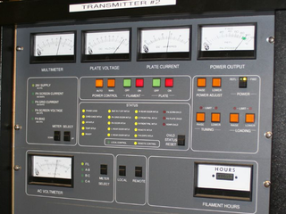
In electronics and telecommunications, a radio transmitter or just transmitter is an electronic device which produces radio waves with an antenna. The transmitter itself generates a radio frequency alternating current, which is applied to the antenna. When excited by this alternating current, the antenna radiates radio waves.

In communications and electronic engineering, an intermediate frequency (IF) is a frequency to which a carrier wave is shifted as an intermediate step in transmission or reception. The intermediate frequency is created by mixing the carrier signal with a local oscillator signal in a process called heterodyning, resulting in a signal at the difference or beat frequency. Intermediate frequencies are used in superheterodyne radio receivers, in which an incoming signal is shifted to an IF for amplification before final detection is done.
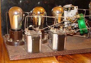
A tetrode is a vacuum tube having four active electrodes. The four electrodes in order from the centre are: a thermionic cathode, first and second grids and a plate. There are several varieties of tetrodes, the most common being the screen-grid tube and the beam tetrode. In screen-grid tubes and beam tetrodes, the first grid is the control grid and the second grid is the screen grid. In other tetrodes one of the grids is a control grid, while the other may have a variety of functions.
A continuous wave or continuous waveform (CW) is an electromagnetic wave of constant amplitude and frequency, typically a sine wave, that for mathematical analysis is considered to be of infinite duration. It may refer to e.g. a laser or particle accelerator having a continuous output, as opposed to a pulsed output.

A regenerative circuit is an amplifier circuit that employs positive feedback. Some of the output of the amplifying device is applied back to its input so as to add to the input signal, increasing the amplification. One example is the Schmitt trigger, but the most common use of the term is in RF amplifiers, and especially regenerative receivers, to greatly increase the gain of a single amplifier stage.
A tuned radio frequency receiver is a type of radio receiver that is composed of one or more tuned radio frequency (RF) amplifier stages followed by a detector (demodulator) circuit to extract the audio signal and usually an audio frequency amplifier. This type of receiver was popular in the 1920s. Early examples could be tedious to operate because when tuning in a station each stage had to be individually adjusted to the station's frequency, but later models had ganged tuning, the tuning mechanisms of all stages being linked together, and operated by just one control knob. By the mid 1930s, it was replaced by the superheterodyne receiver patented by Edwin Armstrong.

In radio communications, a radio receiver, also known as a receiver, a wireless, or simply a radio, is an electronic device that receives radio waves and converts the information carried by them to a usable form. It is used with an antenna. The antenna intercepts radio waves and converts them to tiny alternating currents which are applied to the receiver, and the receiver extracts the desired information. The receiver uses electronic filters to separate the desired radio frequency signal from all the other signals picked up by the antenna, an electronic amplifier to increase the power of the signal for further processing, and finally recovers the desired information through demodulation.

In a radio receiver, a beat frequency oscillator or BFO is a dedicated oscillator used to create an audio frequency signal from Morse code radiotelegraphy (CW) transmissions to make them audible. The signal from the BFO is mixed with the received signal to create a heterodyne or beat frequency which is heard as a tone in the speaker. BFOs are also used to demodulate single-sideband (SSB) signals, making them intelligible, by essentially restoring the carrier that was suppressed at the transmitter. BFOs are sometimes included in communications receivers designed for short wave listeners; they are almost always found in communication receivers for amateur radio, which often receive CW and SSB signals.

A spark-gap transmitter is an obsolete type of radio transmitter which generates radio waves by means of an electric spark. Spark-gap transmitters were the first type of radio transmitter, and were the main type used during the wireless telegraphy or "spark" era, the first three decades of radio, from 1887 to the end of World War I. German physicist Heinrich Hertz built the first experimental spark-gap transmitters in 1887, with which he proved the existence of radio waves and studied their properties.
A direct-conversion receiver (DCR), also known as homodyne, synchrodyne, or zero-IF receiver, is a radio receiver design that demodulates the incoming radio signal using synchronous detection driven by a local oscillator whose frequency is identical to, or very close to the carrier frequency of the intended signal. This is in contrast to the standard superheterodyne receiver where this is accomplished only after an initial conversion to an intermediate frequency.

The Neutrodyne radio receiver, invented in 1922 by Louis Hazeltine, was a particular type of tuned radio frequency (TRF) receiver, in which the instability-causing inter-electrode capacitance of the triode RF tubes is cancelled out or "neutralized" to prevent parasitic oscillations which caused "squealing" or "howling" noises in the speakers of early radio sets. In most designs, a small extra winding on each of the RF amplifiers' tuned anode coils was used to generate a small antiphase signal, which could be adjusted by special variable trim capacitors to cancel out the stray signal coupled to the grid via plate-to-grid capacitance. The Neutrodyne circuit was popular in radio receivers until the 1930s, when it was superseded by the superheterodyne receiver.
Radio receiver design includes the electronic design of different components of a radio receiver which processes the radio frequency signal from an antenna in order to produce usable information such as audio. The complexity of a modern receiver and the possible range of circuitry and methods employed are more generally covered in electronics and communications engineering. The term radio receiver is understood in this article to mean any device which is intended to receive a radio signal in order to generate useful information from the signal, most notably a recreation of the so-called baseband signal which modulated the radio signal at the time of transmission in a communications or broadcast system.

In radio, a detector is a device or circuit that extracts information from a modulated radio frequency current or voltage. The term dates from the first three decades of radio (1888-1918). Unlike modern radio stations which transmit sound on an uninterrupted carrier wave, early radio stations transmitted information by radiotelegraphy. The transmitter was switched on and off to produce long or short periods of radio waves, spelling out text messages in Morse code. Therefore, early radio receivers did not have to demodulate the radio signal, but just distinguish between the presence or absence of a radio signal, to reproduce the Morse code "dots" and "dashes". The device that performed this function in the receiver circuit was called a detector. A variety of different detector devices, such as the coherer, electrolytic detector, magnetic detector and the crystal detector, were used during the wireless telegraphy era until superseded by vacuum tube technology.

A reflex radio receiver, occasionally called a reflectional receiver, is a radio receiver design in which the same amplifier is used to amplify the high-frequency radio signal (RF) and low-frequency audio (sound) signal (AF). It was first invented in 1914 by German scientists Wilhelm Schloemilch and Otto von Bronk, and rediscovered and extended to multiple tubes in 1917 by Marius Latour and William H. Priess. The radio signal from the antenna and tuned circuit passes through an amplifier, is demodulated in a detector which extracts the audio signal from the radio carrier, and the resulting audio signal passes again through the same amplifier for audio amplification before being applied to the earphone or loudspeaker. The reason for using the amplifier for "double duty" was to reduce the number of active devices, vacuum tubes or transistors, required in the circuit, to reduce the cost. The economical reflex circuit was used in inexpensive vacuum tube radios in the 1920s, and was revived again in simple portable tube radios in the 1930s.
A tikker, alternately spelled ticker, was a vibrating interrupter used in early wireless telegraphy radio receivers such as crystal radio receivers in order to receive continuous wave (CW) radiotelegraphy signals.
