In physics, attenuation or, in some contexts, extinction is the gradual loss of flux intensity through a medium. For instance, dark glasses attenuate sunlight, lead attenuates X-rays, and water and air attenuate both light and sound at variable attenuation rates.
The optical power budget in a fiber-optic communication link is the allocation of available optical power among various loss-producing mechanisms such as launch coupling loss, fiber attenuation, splice losses, and connector losses, in order to ensure that adequate signal strength is available at the receiver. In optical power budget attenuation is specified in decibel (dB) and optical power in dBm.
An optical switch is a device that enables optical signals to be selectively switched-on and -off or switched from one channel to another. The former is known as an optical (time-domain) switch or an optical modulator, while the latter can be specifically called an optical space switch or an optical router. In its ways to be switched temporally or spatially, it can be seen as physical analogies to the one-way or two-way switches in electrical circuits. In general, optical modulators and routers can be made from each other.

In fiber-optic communication, a single-mode optical fiber (SMF) is an optical fiber designed to carry light only directly down the fiber - the transverse mode. Modes are the possible solutions of the Helmholtz equation for waves, which is obtained by combining Maxwell's equations and the boundary conditions. These modes define the way the wave travels through space, i.e. how the wave is distributed in space. Waves can have the same mode but have different frequencies. This is the case in single-mode fibers, where we can have waves with different frequencies, but of the same mode, which means that they are distributed in space in the same way, and that gives us a single ray of light. Although the ray travels parallel to the length of the fiber, it is often called transverse mode since its electromagnetic oscillations occur perpendicular (transverse) to the length of the fiber. The 2009 Nobel Prize in Physics was awarded to Charles K. Kao for his theoretical work on the single-mode optical fiber.

A fiberscope is a flexible optical fiber bundle with an eyepiece on one end and a lens on the other that is used to examine and inspect small, difficult-to-reach places such as the insides of machines, locks, and the human body.
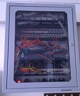
Hybrid fiber-coaxial (HFC) is a telecommunications industry term for a broadband network that combines optical fiber and coaxial cable. It has been commonly employed globally by cable television operators since the early 1990s.

In physics, backscatter is the reflection of waves, particles, or signals back to the direction from which they came. It is a diffuse reflection due to scattering, as opposed to specular reflection as from a mirror. Backscattering has important applications in astronomy, photography, and medical ultrasonography. The opposite effect is forward scatter, e.g. when a translucent material like a cloud diffuses sunlight, giving soft light.

Photonic-crystal fiber (PCF) is a class of optical fiber based on the properties of photonic crystals. It was first explored in 1996 at University of Bath, UK. Because of its ability to confine light in hollow cores or with confinement characteristics not possible in conventional optical fiber, PCF is now finding applications in fiber-optic communications, fiber lasers, nonlinear devices, high-power transmission, highly sensitive gas sensors, and other areas. More specific categories of PCF include photonic-bandgap fiber, holey fiber, hole-assisted fiber, and Bragg fiber. Photonic crystal fibers may be considered a subgroup of a more general class of microstructured optical fibers, where light is guided by structural modifications, and not only by refractive index differences.

A fibre optic gyroscope (FOG) senses changes in orientation using the Sagnac effect, thus performing the function of a mechanical gyroscope. However its principle of operation is instead based on the interference of light which has passed through a coil of optical fibre, which can be as long as 5 km.
Optical networking is a means of communication that uses signals encoded onto light to transmit information among various nodes of a telecommunications network. They operate from the limited range of a local-area network (LAN) or over a wide-area network (WAN), which can cross metropolitan and regional areas all the way to national, international and transoceanic distances. It is a form of optical communication that relies on optical amplifiers, lasers or LEDs and wave division multiplexing (WDM) to transmit large quantities of data, generally across fiber-optic cables. Because it is capable of achieving extremely high bandwidth, it is an enabling technology for today’s Internet and the communication networks that transmit the vast majority of all human and machine-to-machine information.
Fiber-optic communication is a method of transmitting information from one place to another by sending pulses of light through an optical fiber. The light forms an electromagnetic carrier wave that is modulated to carry information. Fiber is preferred over electrical cabling when high bandwidth, long distance, or immunity to electromagnetic interference are required.

An optical power meter (OPM) is a device used measure the power in an optical signal. The term usually refers to a device for testing average power in fiber optic systems. Other general purpose light power measuring devices are usually called radiometers, photometers, laser power meters, light meters or lux meters.
Radio over fiber (RoF) or RF over fiber (RFoF) refers to a technology whereby light is modulated by a radio frequency signal and transmitted over an optical fiber link. Main technical advantages of using fiber optical links are lower transmission losses and reduced sensitivity to noise and electromagnetic interference compared to all-electrical signal transmission.
A fiber optic sensor is a sensor that uses optical fiber either as the sensing element, or as a means of relaying signals from a remote sensor to the electronics that process the signals. Fibers have many uses in remote sensing. Depending on the application, fiber may be used because of its small size, or because no electrical power is needed at the remote location, or because many sensors can be multiplexed along the length of a fiber by using light wavelength shift for each sensor, or by sensing the time delay as light passes along the fiber through each sensor. Time delay can be determined using a device such as an optical time-domain reflectometer and wavelength shift can be calculated using an instrument implementing optical frequency domain reflectometry.
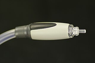
TOSLINK is a standardized optical fiber connector system. Also known generically as an "optical audio cable" or just "optical cable", its most common use is in consumer audio equipment, where it carries a digital audio stream from components such as CD and DVD players, DAT recorders, computers, and modern video game consoles, to an AV receiver that can decode two channels of uncompressed lossless PCM audio or compressed 5.1/7.1 surround sound such as Dolby Digital or DTS Surround System. Unlike HDMI, TOSLINK does not have the bandwidth to carry the lossless versions of Dolby TrueHD, DTS-HD Master Audio, or more than two channels of PCM audio.
Rayleigh scattering based distributed acoustic sensing (DAS) systems use fiber optic cables to provide distributed strain sensing. In DAS, the optical fiber cable becomes the sensing element and measurements are made, and in part processed, using an attached optoelectronic device. Such a system allows acoustic frequency strain signals to be detected over large distances and in harsh environments.