Related Research Articles
A valve is a device or natural object that regulates, directs or controls the flow of a fluid by opening, closing, or partially obstructing various passageways. Valves are technically fittings, but are usually discussed as a separate category. In an open valve, fluid flows in a direction from higher pressure to lower pressure. The word is derived from the Latin valva, the moving part of a door, in turn from volvere, to turn, roll.

A safety valve is a valve that acts as a fail-safe. An example of safety valve is a pressure relief valve (PRV), which automatically releases a substance from a boiler, pressure vessel, or other system, when the pressure or temperature exceeds preset limits. Pilot-operated relief valves are a specialized type of pressure safety valve. A leak tight, lower cost, single emergency use option would be a rupture disk.

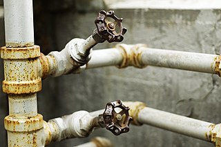
A tap is a valve controlling the release of a liquid or gas.

The J-2 was a liquid-fuel cryogenic rocket engine used on NASA's Saturn IB and Saturn V launch vehicles. Built in the U.S. by Rocketdyne, the J-2 burned cryogenic liquid hydrogen (LH2) and liquid oxygen (LOX) propellants, with each engine producing 1,033.1 kN (232,250 lbf) of thrust in vacuum. The engine's preliminary design dates back to recommendations of the 1959 Silverstein Committee. Rocketdyne won approval to develop the J-2 in June 1960 and the first flight, AS-201, occurred on 26 February 1966. The J-2 underwent several minor upgrades over its operational history to improve the engine's performance, with two major upgrade programs, the de Laval nozzle-type J-2S and aerospike-type J-2T, which were cancelled after the conclusion of the Apollo program.

A relief valve or pressure relief valve (PRV) is a type of safety valve used to control or limit the pressure in a system; pressure might otherwise build up and create a process upset, instrument or equipment failure, or fire. The pressure is relieved by allowing the pressurized fluid to flow from an auxiliary passage out of the system. The relief valve is designed or set to open at a predetermined set pressure to protect pressure vessels and other equipment from being subjected to pressures that exceed their design limits. When the set pressure is exceeded, the relief valve becomes the "path of least resistance" as the valve is forced open and a portion of the fluid is diverted through the auxiliary route. In systems containing flammable fluids, the diverted fluid is usually routed through a piping system known as a flare header or relief header to a central, elevated gas flare where it is usually burned and the resulting combustion gases are released to the atmosphere. In non-hazardous systems, the fluid is often discharged to the atmosphere by a suitable discharge pipework designed to prevent rainwater ingress which can affect the set lift pressure, and positioned not to cause a hazard to personnel. As the fluid is diverted, the pressure inside the vessel will stop rising. Once it reaches the valve's reseating pressure, the valve will close. The blowdown is usually stated as a percentage of set pressure and refers to how much the pressure needs to drop before the valve reseats. The blowdown can vary from roughly 2–20%, and some valves have adjustable blowdowns.

Hydraulic machines use liquid fluid power to perform work. Heavy construction vehicles are a common example. In this type of machine, hydraulic fluid is pumped to various hydraulic motors and hydraulic cylinders throughout the machine and becomes pressurized according to the resistance present. The fluid is controlled directly or automatically by control valves and distributed through hoses, tubes, and/or pipes.

In petroleum and natural gas extraction, a Christmas tree, or "tree", is an assembly of valves, casing spools, and fittings used to regulate the flow of pipes in an oil well, gas well, water injection well, water disposal well, gas injection well, condensate well and other types of wells.
A piping and instrumentation diagram (P&ID) is a detailed diagram in the process industry which shows the piping and process equipment together with the instrumentation and control devices.
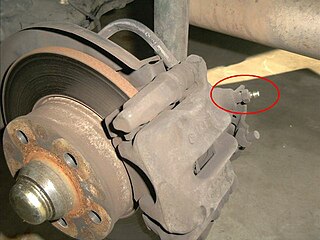
Brake bleeding is the procedure performed on hydraulic brake systems whereby the brake lines are purged of any air bubbles. This is necessary because, while the brake fluid is an incompressible liquid, air bubbles are compressible gas and their presence in the brake system greatly reduces the hydraulic pressure that can be developed within the system. The same methods used for bleeding are also used for brake flushing or purging, where the old fluid is replaced with new fluid, which is necessary maintenance.

A drill stem test (DST) is a procedure for isolating and testing the pressure, permeability and productive capacity of a geological formation during the drilling of a well. The test is an important measurement of pressure behaviour at the drill stem and is a valuable way of obtaining information on the formation fluid and establishing whether a well has found a commercial hydrocarbon reservoir.
A Block and bleed manifold is a hydraulic manifold that combines one or more block/isolate valves, usually ball valves, and one or more bleed/vent valves, usually ball or needle valves, into one component for interface with other components of a hydraulic (fluid) system. The purpose of the block and bleed manifold is to isolate or block the flow of fluid in the system so the fluid from upstream of the manifold does not reach other components of the system that are downstream. Then they bleed off or vent the remaining fluid from the system on the downstream side of the manifold. For example, a block and bleed manifold would be used to stop the flow of fluids to some component, then vent the fluid from that component’s side of the manifold, in order to effect some kind of work (maintenance/repair/replacement) on that component.
A control valve is a valve used to control fluid flow by varying the size of the flow passage as directed by a signal from a controller. This enables the direct control of flow rate and the consequential control of process quantities such as pressure, temperature, and liquid level.
A blowdown stack is an elevated vent or vertical stack that is used to vent the pressure of components of a chemical, refinery or other plant if there is a process problem or emergency. A blowdown stack can be used to complement a flare stack or as an alternative. The purpose is to prevent 'loss of containment' of volatile liquids and gases. Blowdown from several systems may be combined in a blowdown header prior to the stack. A knock-out pot may be provided at the base of the stack to remove any liquids. Blowdown stacks may either be ignited or un-ignited. The height of the blowdown stack must be tall enough to ensure the safe dispersal of vapour.

A valve actuator is the mechanism for opening and closing a valve. Manually operated valves require someone in attendance to adjust them using a direct or geared mechanism attached to the valve stem. Power-operated actuators, using gas pressure, hydraulic pressure or electricity, allow a valve to be adjusted remotely, or allow rapid operation of large valves. Power-operated valve actuators may be the final elements of an automatic control loop which automatically regulates some flow, level or other process. Actuators may be only to open and close the valve, or may allow intermediate positioning; some valve actuators include switches or other ways to remotely indicate the position of the valve.
The term separator in oilfield terminology designates a pressure vessel used for separating well fluids produced from oil and gas wells into gaseous and liquid components. A separator for petroleum production is a large vessel designed to separate production fluids into their constituent components of oil, gas and water. A separating vessel may be referred to in the following ways: Oil and gas separator, Separator, Stage separator, Trap, Knockout vessel, Flash chamber, Expansion separator or expansion vessel, Scrubber, Filter. These separating vessels are normally used on a producing lease or platform near the wellhead, manifold, or tank battery to separate fluids produced from oil and gas wells into oil and gas or liquid and gas. An oil and gas separator generally includes the following essential components and features:
A high-integrity pressure protection system (HIPPS) is a type of safety instrumented system (SIS) designed to prevent over-pressurization of a plant, such as a chemical plant or oil refinery. The HIPPS will shut off the source of the high pressure before the design pressure of the system is exceeded, thus preventing loss of containment through rupture (explosion) of a line or vessel. Therefore, a HIPPS is considered as a barrier between a high-pressure and a low-pressure section of an installation.
Surge control is the use of different techniques and equipment in a hydraulic system to prevent any excessive gain in pressure that would cause the hydraulic process pressure to exceed the maximum working pressure of the mechanical equipment used in the system.
Instrumentation is used to monitor and control the process plant in the oil, gas and petrochemical industries. Instrumentation comprises sensor elements, signal transmitters, controllers, indicators and alarms, actuated valves, logic circuits and operator interfaces.
References
- ↑ Nesbitt, Brian (19 April 2011). Handbook of Valves and Actuators. p. 82. ISBN 9780080549286.
- ↑ Royals, William T. (1997). Flammability and sensitivity of materials in oxygen-enriched atmospheres. American Society for Testing and Materials. p. 433. ISBN 0-8031-2401-5.
- 1 2 3 Green, John W (1997). Perry's chemical engineers' handbook. McGraw Hill. pp. Section 10 - Transport and Storage of Fluids. ISBN 0-07-049841-5.
- 1 2 Gas Processors Suppliers Association (2004). Engineering Data Book. Tulsa, Oklahoma: Gas Processors Suppliers Association. pp. Section 17 Fluid Flow and Piping.
- 1 2 3 4 HSE (2006). "The safe isolation of plant and equipment" (PDF). Health and Safety Executive. Retrieved 2 December 2019.
- ↑ Nolan, Dennis (2011). Handbook of Fire and Explosion Protection Engineering Principles: For Oil. Elsevier, Inc. p. 220. ISBN 978-1-4377-7857-1.
- ↑ Menon, E. Shashi (2011). Pipeline Planning and Construction Field Manual. Elsevier, Inc. p. 396. ISBN 9780123838544.
- ↑ Joyce, Michael A. (2012). Residential Construction Academy - Plumbing, Second Edition. Delmar, Cengage Learning. p. 116. ISBN 978-1-111-30777-6.
- ↑ "Information Notice No. 85-71: CONTAINMENT INTEGRATED LEAK RATE TESTS". United States Nuclear Regulatory Commission. Retrieved 25 February 2012.
- ↑ McAleese, Stuart (2000). Operational aspects of oil and gas well testing. Elsevier. p. 69. ISBN 0-444-50311-0.