NACA airfoil

Last updated
Profile geometry - 1: Zero-lift line; 2: Leading edge; 3: Nose circle; 4: Max. thickness; 5: Camber; 6: Upper surface; 7: Trailing edge; 8: Camber mean-line; 9: Lower surface Airfoil geometry.svg
Profile geometry – 1: Zero-lift line; 2: Leading edge; 3: Nose circle; 4: Max. thickness; 5: Camber; 6: Upper surface; 7: Trailing edge; 8: Camber mean-line; 9: Lower surface
Profile lines - 1: Chord, 2: Camber, 3: Length, 4: Midline Airfoil lines.png
Profile lines – 1: Chord, 2: Camber, 3: Length, 4: Midline
A: blue line = chord, green line = camber mean-line, B: leading-edge radius, C: xy coordinates for the profile geometry (chord = x axis; y axis line on that leading edge) NACA Profil 0.svg
A: blue line = chord, green line = camber mean-line, B: leading-edge radius, C: xy coordinates for the profile geometry (chord = x axis; y axis line on that leading edge)

NACA stands for the National Advisory Committee for Aeronautics, which was a U.S. federal agency founded in 1915 to undertake, promote, and institutionalize aeronautical research. It played a crucial role in advancing aviation technology, including the development of airfoils, which are the cross-sectional shapes of wings and other aerodynamic surfaces. The NACA airfoil series is a set of standardized airfoil shapes developed by this agency, which became widely used in the design of aircraft wings.

Contents

Origins

NACA initially developed the numbered airfoil system which was further refined by the United States Air Force at Langley Research Center. According to the NASA website:

During the late 1920s and into the 1930s, the NACA developed a series of thoroughly tested airfoils and devised a numerical designation for each airfoil — a four digit number that represented the airfoil section's critical geometric properties. By 1929, Langley had developed this system to the point where the numbering system was complemented by an airfoil cross-section, and the complete catalog of 78 airfoils appeared in the NACA's annual report for 1933. Engineers could quickly see the peculiarities of each airfoil shape, and the numerical designator ("NACA 2415," for instance) specified camber lines, maximum thickness, and special nose features. These figures and shapes transmitted the sort of information to engineers that allowed them to select specific airfoils for desired performance characteristics of specific aircraft. [1]

Four-digit series

The NACA four-digit wing sections define the profile by: [2]

  1. First digit describing maximum camber as percentage of the chord.
  2. Second digit describing the distance of maximum camber from the airfoil leading edge in tenths of the chord.
  3. Last two digits describing maximum thickness of the airfoil as percent of the chord. [3]

For example, the NACA 2412 airfoil has a maximum camber of 2% located 40% (0.4 chords) from the leading edge with a maximum thickness of 12% of the chord.

The NACA 0015 airfoil is symmetrical, the 00 indicating that it has no camber. The 15 indicates that the airfoil has a 15% thickness to chord length ratio: it is 15% as thick as it is long.

Equation for a symmetrical 4-digit NACA airfoil

Plot of a NACA 0015 foil generated from formula NACA0015 a.png
Plot of a NACA 0015 foil generated from formula

The formula for the shape of a NACA 00xx foil, with "xx" being replaced by the percentage of thickness to chord, is [4]

[5] [6]

where:

x is the position along the chord from 0 to 1.00 (0 to 100%),
is the half thickness at a given value of x (centerline to surface),
t is the maximum thickness as a fraction of the chord (so t gives the last two digits in the NACA 4-digit denomination divided by 100).

In this equation, at x = 1 (the trailing edge of the airfoil), the thickness is not quite zero. If a zero-thickness trailing edge is required, for example for computational work, one of the coefficients should be modified such that they sum to zero. Modifying the last coefficient (i.e. to −0.1036) will result in the smallest change to the overall shape of the airfoil. The leading edge approximates a cylinder with a chord-normalized radius of

[7]

Now the coordinates of the upper airfoil surface and of the lower airfoil surface are

Symmetrical 4-digit series airfoils by default have maximum thickness at 30% of the chord from the leading edge.

Equation for a cambered 4-digit NACA airfoil

Plot of a NACA 2412 foil. The camber line is shown in red, and the thickness - or the symmetrical airfoil 0012 - is shown in purple. NACA 2412.png
Plot of a NACA 2412 foil. The camber line is shown in red, and the thickness – or the symmetrical airfoil 0012 – is shown in purple.

The simplest asymmetric foils are the NACA 4-digit series foils, which use the same formula as that used to generate the 00xx symmetric foils, but with the line of mean camber bent. The formula used to calculate the mean camber line is [4]

where

m is the maximum camber (100 m is the first of the four digits),
p is the location of maximum camber (10 p is the second digit in the NACA xxxx description).

For example, a NACA 2412 airfoil uses a 2% camber (first digit) 40% (second digit) along the chord of a 0012 symmetrical airfoil having a thickness 12% (digits 3 and 4) of the chord.

For this cambered airfoil, because the thickness needs to be applied perpendicular to the camber line, the coordinates and , of respectively the upper and lower airfoil surface, become [8]

where

Five-digit series

The NACA five-digit series describes more complex airfoil shapes. [9] Its format is LPSTT, where:

For example, the NACA 23112 profile describes an airfoil with design lift coefficient of 0.3 (0.15 × 2), the point of maximum camber located at 15% chord (5 × 3), reflex camber (1), and maximum thickness of 12% of chord length (12).

The camber line for the simple case (S = 0) is defined in two sections: [10]

where the chordwise location and the ordinate have been normalized by the chord. The constant is chosen so that the maximum camber occurs at ; for example, for the 230 camber line, and . Finally, constant is determined to give the desired lift coefficient. For a 230 camber-line profile (the first 3 numbers in the 5-digit series), is used.

Non-reflexed 3 digit camber lines

3-digit camber lines provide a very far forward location for the maximum camber.

The camber line is defined as [10]

with the camber line gradient

The following table presents the various camber-line profile coefficients for a theoretical design lift coefficient of 0.3 - the value of must be linearly scaled for a different desired design lift coefficient: [11]

Camber-line profile
2100.050.0580361.40
2200.100.12651.640
2300.150.202515.957
2400.200.2906.643
2500.250.3913.230

Reflexed 3-digit camber lines

Camber lines such as 231 makes the negative trailing edge camber of the 230 series profile to be positively cambered. This results in a theoretical pitching moment of 0.

From

From

The following table presents the various camber-line profile coefficients for a theoretical design lift coefficient of 0.3 - the value of , and must be linearly scaled for a different desired design lift coefficient: [11]

Camber-line profile
2210.100.13051.9900.000764
2310.150.21715.7930.00677
2410.200.3186.5200.0303
2510.250.4413.1910.1355

Modifications

Four- and five-digit series airfoils can be modified with a two-digit code preceded by a hyphen in the following sequence:

  1. One digit describing the roundness of the leading edge, with 0 being sharp, 6 being the same as the original airfoil, and larger values indicating a more rounded leading edge.
  2. One digit describing the distance of maximum thickness from the leading edge in tenths of the chord.

For example, the NACA 1234-05 is a NACA 1234 airfoil with a sharp leading edge and maximum thickness 50% of the chord (0.5 chords) from the leading edge.

In addition, for a more precise description of the airfoil all numbers can be presented as decimals.

1-series

A new approach to airfoil design was pioneered in the 1930s, in which the airfoil shape was mathematically derived from the desired lift characteristics. Prior to this, airfoil shapes were first created and then had their characteristics measured in a wind tunnel. The 1-series airfoils are described by five digits in the following sequence:

  1. The number "1" indicating the series.
  2. One digit describing the distance of the minimum-pressure area in tenths of chord.
  3. A hyphen.
  4. One digit describing the lift coefficient in tenths.
  5. Two digits describing the maximum thickness in percent of chord.

For example, the NACA 16-123 airfoil has minimum pressure 60% of the chord back with a lift coefficient of 0.1 and maximum thickness of 23% of the chord.

6-series

An improvement over 1-series airfoils with emphasis on maximizing laminar flow. The airfoil is described using six digits in the following sequence:

  1. The number "6" indicating the series.
  2. One digit describing the distance of the minimum pressure area in tenths of the chord.
  3. The subscript digit gives the range of lift coefficient in tenths above and below the design lift coefficient in which favorable pressure gradients exist on both surfaces.
  4. A hyphen.
  5. One digit describing the design lift coefficient in tenths.
  6. Two digits describing the maximum thickness as percent of chord.
  7. "a=" followed by a decimal number describing the fraction of chord over which laminar flow is maintained. a=1 is the default if no value is given.


For example, the NACA 654-415, has the minimum pressure placed at 50% of the chord, has a maximum thickness of 15% of the chord, design lift coefficient of 0.4 and maintains laminar flow for lift coefficients between 0 and 0.8.

7-series

Further advancement in maximizing laminar flow achieved by separately identifying the low-pressure zones on upper and lower surfaces of the airfoil. The airfoil is described by seven digits in the following sequence:

  1. The number "7" indicating the series.
  2. One digit describing the distance of the minimum pressure area on the upper surface in tenths of the chord.
  3. One digit describing the distance of the minimum pressure area on the lower surface in tenths of the chord.
  4. One letter referring to a standard profile from the earlier NACA series.
  5. One digit describing the lift coefficient in tenths.
  6. Two digits describing the maximum thickness as percent of chord.

For example, the NACA 712A315 has the area of minimum pressure 10% of the chord back on the upper surface and 20% of the chord back on the lower surface, uses the standard "A" profile, has a lift coefficient of 0.3, and has a maximum thickness of 15% of the chord.

8-series

Supercritical airfoils designed to independently maximize laminar flow above and below the wing. The numbering is identical to the 7-series airfoils except that the sequence begins with an "8" to identify the series.

See also

Related Research Articles

<i>p</i>-adic number Number system extending the rational numbers

In number theory, given a prime number p, the p-adic numbers form an extension of the rational numbers which is distinct from the real numbers, though with some similar properties; p-adic numbers can be written in a form similar to decimals, but with digits based on a prime number p rather than ten, and extending to the left rather than to the right.

<span class="mw-page-title-main">Chebyshev polynomials</span> Polynomial sequence

The Chebyshev polynomials are two sequences of polynomials related to the cosine and sine functions, notated as and . They can be defined in several equivalent ways, one of which starts with trigonometric functions:

<span class="mw-page-title-main">Aircraft flight dynamics</span> Science of air vehicle orientation and control in three dimensions

Flight dynamics is the science of air vehicle orientation and control in three dimensions. The three critical flight dynamics parameters are the angles of rotation in three dimensions about the vehicle's center of gravity (cg), known as pitch, roll and yaw. These are collectively known as aircraft attitude, often principally relative to the atmospheric frame in normal flight, but also relative to terrain during takeoff or landing, or when operating at low elevation. The concept of attitude is not specific to fixed-wing aircraft, but also extends to rotary aircraft such as helicopters, and dirigibles, where the flight dynamics involved in establishing and controlling attitude are entirely different.

<span class="mw-page-title-main">Beta function</span> Mathematical function

In mathematics, the beta function, also called the Euler integral of the first kind, is a special function that is closely related to the gamma function and to binomial coefficients. It is defined by the integral

<span class="mw-page-title-main">Aspect ratio (aeronautics)</span> Ratio of an aircrafts wing span to its mean chord

In aeronautics, the aspect ratio of a wing is the ratio of its span to its mean chord. It is equal to the square of the wingspan divided by the wing area. Thus, a long, narrow wing has a high aspect ratio, whereas a short, wide wing has a low aspect ratio.

<span class="mw-page-title-main">Airfoil</span> Cross-sectional shape of a wing, blade of a propeller, rotor, or turbine, or sail

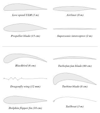
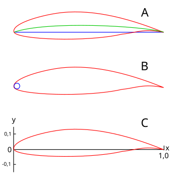
An airfoil or aerofoil is a streamlined body that is capable of generating significantly more lift than drag. Wings, sails and propeller blades are examples of airfoils. Foils of similar function designed with water as the working fluid are called hydrofoils.

In fluid dynamics, the lift coefficient is a dimensionless quantity that relates the lift generated by a lifting body to the fluid density around the body, the fluid velocity and an associated reference area. A lifting body is a foil or a complete foil-bearing body such as a fixed-wing aircraft. CL is a function of the angle of the body to the flow, its Reynolds number and its Mach number. The section lift coefficient cl refers to the dynamic lift characteristics of a two-dimensional foil section, with the reference area replaced by the foil chord.

In probability theory, the Vysochanskij–Petunin inequality gives a lower bound for the probability that a random variable with finite variance lies within a certain number of standard deviations of the variable's mean, or equivalently an upper bound for the probability that it lies further away. The sole restrictions on the distribution are that it be unimodal and have finite variance; here unimodal implies that it is a continuous probability distribution except at the mode, which may have a non-zero probability.

Blade element theory (BET) is a mathematical process originally designed by William Froude (1878), David W. Taylor (1893) and Stefan Drzewiecki (1885) to determine the behavior of propellers. It involves breaking a blade down into several small parts then determining the forces on each of these small blade elements. These forces are then integrated along the entire blade and over one rotor revolution in order to obtain the forces and moments produced by the entire propeller or rotor. One of the key difficulties lies in modelling the induced velocity on the rotor disk. Because of this the blade element theory is often combined with momentum theory to provide additional relationships necessary to describe the induced velocity on the rotor disk, producing blade element momentum theory. At the most basic level of approximation a uniform induced velocity on the disk is assumed:

In fluid dynamics, the pressure coefficient is a dimensionless number which describes the relative pressures throughout a flow field. The pressure coefficient is used in aerodynamics and hydrodynamics. Every point in a fluid flow field has its own unique pressure coefficient, Cp.

<span class="mw-page-title-main">Flap (aeronautics)</span> Anti-stalling high-lift device on aircraft

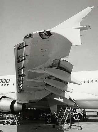
A flap is a high-lift device used to reduce the stalling speed of an aircraft wing at a given weight. Flaps are usually mounted on the wing trailing edges of a fixed-wing aircraft. Flaps are used to reduce the take-off distance and the landing distance. Flaps also cause an increase in drag so they are retracted when not needed.

In thermodynamics, the heat transfer coefficient or film coefficient, or film effectiveness, is the proportionality constant between the heat flux and the thermodynamic driving force for the flow of heat. It is used in calculating the heat transfer, typically by convection or phase transition between a fluid and a solid. The heat transfer coefficient has SI units in watts per square meter per kelvin (W/m2K).

In aeronautics and aeronautical engineering, camber is the asymmetry between the two acting surfaces of an airfoil, with the top surface of a wing commonly being more convex. An airfoil that is not cambered is called a symmetric airfoil. The benefits of cambering were discovered and first utilized by George Cayley in the early 19th century.

<span class="mw-page-title-main">Aerodynamic center</span> Point on an airfoil where pitching moment coefficient is constant for all angles of attack

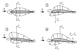
In aerodynamics, the torques or moments acting on an airfoil moving through a fluid can be accounted for by the net lift and net drag applied at some point on the airfoil, and a separate net pitching moment about that point whose magnitude varies with the choice of where the lift is chosen to be applied. The aerodynamic center is the point at which the pitching moment coefficient for the airfoil does not vary with lift coefficient, making analysis simpler.

<span class="mw-page-title-main">Pitching moment</span> Torque on an airfoil from forces applied at the aerodynamic center

In aerodynamics, the pitching moment on an airfoil is the moment produced by the aerodynamic force on the airfoil if that aerodynamic force is considered to be applied, not at the center of pressure, but at the aerodynamic center of the airfoil. The pitching moment on the wing of an airplane is part of the total moment that must be balanced using the lift on the horizontal stabilizer. More generally, a pitching moment is any moment acting on the pitch axis of a moving body.

The Prandtl lifting-line theory is a mathematical model in aerodynamics that predicts lift distribution over a three-dimensional wing based on its geometry. It is also known as the Lanchester–Prandtl wing theory.

A repeating decimal or recurring decimal is a decimal representation of a number whose digits are eventually periodic ; if this sequence consists only of zeros, the decimal is said to be terminating, and is not considered as repeating. It can be shown that a number is rational if and only if its decimal representation is repeating or terminating. For example, the decimal representation of 1/3 becomes periodic just after the decimal point, repeating the single digit "3" forever, i.e. 0.333.... A more complicated example is 3227/555, whose decimal becomes periodic at the second digit following the decimal point and then repeats the sequence "144" forever, i.e. 5.8144144144.... Another example of this is 593/53, which becomes periodic after the decimal point, repeating the 13-digit pattern "1886792452830" forever, i.e. 11.18867924528301886792452830....

<span class="mw-page-title-main">Falkner–Skan boundary layer</span> Boundary layer that forms on a wedge

In fluid dynamics, the Falkner–Skan boundary layer describes the steady two-dimensional laminar boundary layer that forms on a wedge, i.e. flows in which the plate is not parallel to the flow. It is also representative of flow on a flat plate with an imposed pressure gradient along the plate length, a situation often encountered in wind tunnel flow. It is a generalization of the flat plate Blasius boundary layer in which the pressure gradient along the plate is zero.

In mathematics, and in particular in mathematical analysis, the Gagliardo–Nirenberg interpolation inequality is a result in the theory of Sobolev spaces that relates the -norms of different weak derivatives of a function through an interpolation inequality. The theorem is of particular importance in the framework of elliptic partial differential equations and was originally formulated by Emilio Gagliardo and Louis Nirenberg in 1958. The Gagliardo-Nirenberg inequality has found numerous applications in the investigation of nonlinear partial differential equations, and has been generalized to fractional Sobolev spaces by Haim Brezis and Petru Mironescu in the late 2010s.

<span class="mw-page-title-main">Dynamic stall on helicopter rotors</span> Dynamic stall on helicopter rotors

The dynamic stall is one of the hazardous phenomena on helicopter rotors, which can cause the onset of large torsional airloads and vibrations on the rotor blades. Unlike fixed-wing aircraft, of which the stall occurs at relatively low flight speed, the dynamic stall on a helicopter rotor emerges at high airspeeds or/and during manoeuvres with high load factors of helicopters, when the angle of attack(AOA) of blade elements varies intensively due to time-dependent blade flapping, cyclic pitch and wake inflow. For example, during forward flight at the velocity close to VNE, velocity, never exceed, the advancing and retreating blades almost reach their operation limits whereas flows are still attached to the blade surfaces. That is, the advancing blades operate at high Mach numbers so low values of AOA is needed but shock-induced flow separation may happen, while the retreating blade operates at much lower Mach numbers but the high values of AoA result in the stall.

References

  1. Allen, Bob (31 January 2017). "NACA Airfoils". nasa.gov. NASA. Retrieved 27 July 2020.
  2. E. N. Jacobs, K. E. Ward, & R. M. Pinkerton. NACA Report No. 460, "The characteristics of 78 related airfoil sections from tests in the variable-density wind tunnel". NACA, 1933.
  3. "Fundamentals of aerodynamics", John D. Anderson, Jr., third ed., ch. 4.
  4. 1 2 Moran, Jack (2003). An introduction to theoretical and computational aerodynamics. Dover. p.  7. ISBN   0-486-42879-6.
  5. Aerospaceweb.org | Ask Us - NACA Airfoil Series
  6. Payne, Greg (8 Jul 1994), NACA 6, 7, and 8 series, archived from the original on April 27, 2009
  7. Gordon J. Leishman. Principles of Helicopter Aerodynamics. p. 361.
  8. Marzocca, Pier. "The NACA airfoil series" (PDF). Clarkson University. Retrieved July 5, 2016.
  9. E. N. Jacobs & R. M. Pinkerton 1936 Test in the variable-density wind tunnel of related airfoils having the maximum camber unusually far forward, NACA Report No. 537.
  10. 1 2 Abbott, Ira; von Doenhoff, Albert (1959). Theory of Wing Sections: Including a Summary of Airfoil Data . New York: Dover Publications. p.  115. ISBN   978-0486605869.
  11. 1 2 C. L. Ladson, C.W. Brooks Jr., A. S. Hill. NASA Technical Memorandum 4741, Computer Program To Obtain Ordinates for NACA Airfoils. Page 7. NASA, 1996.