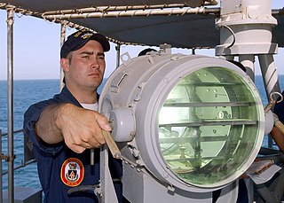
Optical communication, also known as optical telecommunication, is communication at a distance using light to carry information. It can be performed visually or by using electronic devices. The earliest basic forms of optical communication date back several millennia, while the earliest electrical device created to do so was the photophone, invented in 1880.

In aviation, the instrument landing system (ILS) is a precision radio navigation system that provides short-range guidance to aircraft to allow them to approach a runway at night or in bad weather. In its original form, it allows an aircraft to approach until it is 200 feet (61 m) over the ground, within a 1⁄2 mile (800 m) of the runway. At that point the runway should be visible to the pilot; if it is not, they perform a missed approach. Bringing the aircraft this close to the runway dramatically increases the range of weather conditions in which a safe landing can be made. Other versions of the system, or "categories", have further reduced the minimum altitudes, runway visual ranges (RVRs), and transmitter and monitoring configurations designed depending on the normal expected weather patterns and airport safety requirements.
In aviation, a go-around is an aborted landing of an aircraft that is on final approach or has already touched down. A go-around can either be initiated by the pilot flying or requested by air traffic control for various reasons, such as an unstabilized approach or an obstruction on the runway.
Aviation is the design, development, production, operation, and use of aircraft, especially heavier-than-air aircraft. Articles related to aviation include:
The visual approach slope indicator (VASI) is a system of lights on the side of an airport runway threshold that provides visual descent guidance information during final approach. These lights may be visible from up to 8 kilometres (5.0 mi) during the day and up to 32 kilometres (20 mi) or more at night.

A precision approach path indicator (PAPI) is a system of lights on the side of an airport runway threshold that provides visual descent guidance information during final approach. It is generally located on the left-hand side of the runway approximately 300 metres (980 ft) beyond the landing threshold of the runway.

In aviation, an instrument approach or instrument approach procedure (IAP) is a series of predetermined maneuvers for the orderly transfer of an aircraft operating under instrument flight rules from the beginning of the initial approach to a landing, or to a point from which a landing may be made visually. These approaches are approved in the European Union by EASA and the respective country authorities and in the United States by the FAA or the United States Department of Defense for the military. The ICAO defines an instrument approach as "a series of predetermined maneuvers by reference to flight instruments with specific protection from obstacles from the initial approach fix, or where applicable, from the beginning of a defined arrival route to a point from which a landing can be completed and thereafter, if landing is not completed, to a position at which holding or en route obstacle clearance criteria apply."

Precision approach radar orPAR is a type of radar guidance system designed to provide lateral and vertical guidance to an aircraft pilot for landing, until the landing threshold is reached. Controllers monitoring the PAR displays observe each aircraft's position and issue instructions to the pilot that keep the aircraft on course and glidepath during final approach. After the aircraft reaches the decision height (DH) or decision altitude (DA), further guidance is advisory only. The overall concept is known as ground-controlled approach (GCA), and this name was also used to refer to the radar systems in the early days of its development.
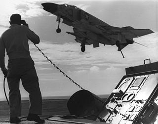
A landing signal officer or landing safety officer (LSO), also informally known as paddles or batsman, is a naval aviator specially trained to facilitate the "safe and expeditious recovery" of naval aircraft aboard aircraft carriers. LSOs aboard smaller air capable ships that launch and recover helicopters are informally known as deck. Originally LSOs were responsible for bringing aircraft aboard ship using hand-operated signals. Since the introduction of optical landing systems in the 1950s, LSOs assist pilots by giving information via radio handsets.

An approach lighting system (ALS) is a lighting system installed on the approach end of an airport runway and consisting of a series of lightbars, strobe lights, or a combination of the two that extends outward from the runway end. ALS usually serves a runway that has an instrument approach procedure (IAP) associated with it and allows the pilot to visually identify the runway environment and align the aircraft with the runway upon arriving at a prescribed point on an approach.
In aviation, a ground-controlled approach (GCA) is a type of service provided by air-traffic controllers whereby they guide aircraft to a safe landing, including in adverse weather conditions, based on primary radar images. Most commonly, a GCA uses information from either a precision approach radar or an airport surveillance radar. The term GCA may refer to any type of ground radar guided approach such as a PAR, PAR without glideslope or ASR. When both vertical and horizontal guidance from the PAR is given, the approach is termed a precision approach. If no PAR glidepath is given, even if PAR equipment is used for lateral guidance, it is considered a non-precision approach.
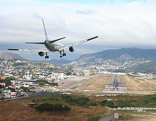
In aeronautics, the final approach is the last leg in an aircraft's approach to landing, when the aircraft is lined up with the runway and descending for landing. In aviation radio terminology, it is often shortened to "final".

Landing lights are lights, mounted on aircraft, that illuminate the terrain and runway ahead during takeoff and landing, as well as being used as a collision avoidance measure against other aircraft and bird strikes. Landing lights must be activated when the aircraft is under 10,000 feet in altitude.

Modern United States Navy aircraft carrier air operations include the operation of fixed-wing and rotary aircraft on and around an aircraft carrier for performance of combat or noncombat missions. The flight operations are highly evolved, based on experiences dating back to 1922 with USS Langley.
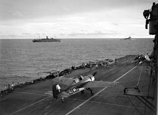
Aircraft carriers are warships that evolved from balloon-carrying wooden vessels into nuclear-powered vessels carrying many dozens of fixed- and rotary-wing aircraft. Since their introduction they have allowed naval forces to project air power great distances without having to depend on local bases for staging aircraft operations.
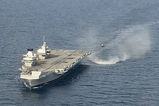
Shipborne rolling vertical landing (SRVL) is a method used to land a V/STOL aircraft that uses both the vertical thrust from the jet engine and lift from the wings.

Aeroflot Flight 99 was a Tupolev Tu-124 operating a scheduled domestic passenger flight from Leningrad to Murmansk, both in the Soviet Union, which crashed while attempting to land on 11 November 1965. Of the 64 passengers and crew on board, 32 were killed in the accident, and many of the survivors sustained injuries.

Delta Air Lines Flight 723 was a flight operated by a McDonnell Douglas DC-9 twin-engine jetliner, operating as a scheduled domestic passenger flight from Burlington, Vermont, to Logan International Airport in Boston, Massachusetts, with an intermediate stop in Manchester, New Hampshire. On July 31, 1973, at 11:08 a.m., while on an instrument landing system (ILS) instrument approach into Logan in low clouds and fog, the aircraft descended below the glidepath, struck a seawall, and crashed. All 89 of the occupants aboard were killed, including an initial survivor who died more than 4 months after the crash.
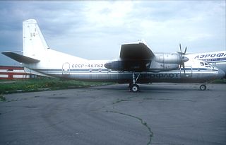
Aeroflot Flight N-36 was a scheduled domestic Aeroflot passenger flight from Chernivtsi International Airport to Zhuliany Airport, Ukrainian Soviet Socialist Republic that crashed on 17 December 1976 near Kiev Airport, resulting in 48 fatalities and 7 survivors.

Training Air Wing ONE is a United States Navy aircraft training air wing based aboard Naval Air Station Meridian, located 11 miles northeast of Meridian, Mississippi in Lauderdale County and Kemper County. TW-1 is one of five training air wings in the Naval Air Training Command, and consists of two jet training squadrons. The wing trains Student Naval Aviators from the U.S. Navy, U.S. Marine Corps, and international allies. Following completion of primary flight training and selection of an advanced training pipeline, Student Naval Aviators are assigned to TW-1 for either intermediate and advanced strike pipeline training or advanced E-2/C-2 training in the T-45C Goshawk jet training aircraft.


