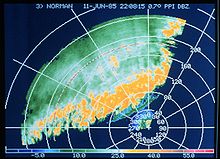
Image of a thunderstorm line (in dBZ) seen on a 0.7-degree elevation PPI (NOAA)Diagram showing the evolution of the height above ground, in kilometers, with the distance to the radar for the 24 PPI angles used on the Canadian weather radars (curved lines)
A plan position indicator (PPI) is a type of radar display that represents the radar antenna in the center of the display, with the distance from it and height above ground drawn as concentric circles. As the radar antenna rotates, a radial trace on the PPI sweeps in unison with it about the center point. It is the most common type of radar display.
The radar antenna sends pulses while rotating 360 degrees around the radar site at a fixed elevation angle. It can then change angle or repeat at the same angle according to the need. Return echoes from targets are received by the antenna and processed by the receiver and the most direct display of those data is the PPI.
The height of the echoes increases with the distance to the radar, as represented in the adjacent image. This change is not a straight line but a curve as the surface of the Earth is curved and sinks below the radar horizon. For fixed-site installations, north is usually represented at the top of the image. For moving installations, such as small ship and aircraft radars, the top may represent the bow or nose of the ship or aircraft, i.e., its heading (direction of travel) and this is usually represented by a lubber line. Some systems may incorporate the input from a gyrocompass to rotate the display and once again display north as "up".
Also, the signal represented is the reflectivity at only one elevation of the antenna, so it is possible to have many PPIs at one time, one for each antenna elevation.
History
A photograph of an H2S PPI display taken during an attack on Cologne. The annotations were added later for post-attack analysis. The Rhine River can clearly be seen.
Originally, data was displayed in real time on a cathode-ray tube (CRT), and thus the only way to store the information received was by taking a photograph of the screen.
Philo Taylor Farnsworth, the American inventor of all-electronic television in September 1927, contributed[citation needed] to this in an important way. Farnsworth refined a version of his picture tube (CRT) and called it an "Iatron;" generically known as a storage tube. It could store an image for milliseconds to minutes and even hours. One version that kept an image alive about a second before fading proved to be useful for radar. This slow-to-fade display tube was used by air traffic controllers from the very beginning of radar usage.
With the development of more sophisticated radar systems, it became possible to digitize data and store it in memory, allowing access at a later date.
Uses
Simplified animation of a Plan Position Indicator radar display
The PPI is used in many domains involving display of range and positioning, especially in radars, including air traffic control, ship navigation, meteorology, on board ships and aircraft etc. PPI displays are also used to display sonar data, especially in underwater warfare. However, because the speed of sound in water is very slow compared to microwaves in air, a sonar PPI has an expanding circle that starts with each transmitted "ping" of sound. In meteorology, a competing display system is the CAPPI (Constant Altitude Plan Position Indicator) when a multi-angle scan is available.
Using computers to process data, modern sonar and lidar installations can mimic radar PPI displays too.[1]
Bibliography
Sir Bernard Lovell ECHOES OF WAR: The Story of H2S RadarISBN0-85274-317-3
Yves Blanchard, Le radar, 1904-2004: histoire d'un siècle d'innovations techniques et opérationnelles , published by Ellipses, Paris, France, 2004 ISBN2-7298-1802-2
Brown, Louis. A Radar History of World War II: Technical and Military Imperatives, Philadelphia, Pa.: Institute of Physics Publishing, 1999.
R. J. Doviak et D. S. Zrnic, Doppler Radar and Weather Observations, Academic Press. Seconde Edition, San Diego Cal., 1993 p.562.
Roger M. Wakimoto and Ramesh Srivastava, Radar and Atmospheric Science: A Collection of Essays in Honor of David Atlas, publié par l'American Meteorological Society, Boston, August 2003. Series: Meteorological Monograph, Volume 30, number 52, 270 pages, ISBN1-878220-57-8; AMS Code MM52.
This page is based on this Wikipedia article Text is available under the CC BY-SA 4.0 license; additional terms may apply. Images, videos and audio are available under their respective licenses.