Robotic non-destructive testing (NDT) is a method of inspection used to assess the structural integrity of petroleum, natural gas, and water installations. Crawler-based robotic tools are commonly used for in-line inspection (ILI) applications in pipelines that cannot be inspected using traditional intelligent pigging tools (or unpiggable pipelines).
Robotic NDT tools can also be used for mandatory inspections in inhospitable areas (e.g., tank interiors, subsea petroleum installations) to minimize danger to human inspectors, as these tools are operated remotely by a trained technician or NDT analyst. These systems transmit data and commands via either a wire (typically called an umbilical cable or tether) or wirelessly (in the case of battery-powered tetherless crawlers).
Applications
Robotic NDT tools help pipeline operators and utility companies complete required structural integrity data sets for maintenance purposes in the following applications:
Technicians can manually adjust robotic tool travel speed, orientation, and configuration to navigate fittings that might trap or damage a free-flowing pig.
Product flow may not be conducive to pig travel.
Technician control of self-propelled crawler travel reduces the risk of velocity-based sensor malfunction.
Real-time tool monitoring allows the technician to adjust the tool run immediately if readings become unacceptable, including adjusting tool settings to re-scan missed areas or repairing damaged components.
Most robotic tools employ non-contact examination methods – technicians are not forced to manage a layer of couplant.
Limited tool access may impact use of traditional tools – smart pigs require special entry and exit points (called launchers and receivers, respectively), which may be permanently or temporarily installed.
Some crawlers can be inserted via removed fittings or cut-out spools as small as 24” in length, providing greater flexibility in launch and retrieval options – these tools do not require special fixtures.
Some crawlers are designed to enter and exit natural gas lines via hot taps, which can be placed at pipeline operator convenience without taking the line out of service.
Even in pipelines that could feasibly accept a traditional smart pig, the ability of crawlers to perform short inspections inside specific areas of concern is much more efficient for pipeline operators than arranging a lengthy pig run just to reach the same small area.
Robotic NDT tools also offer safety advantages in inhospitable areas:
Tank shell inspection crawlers typically climb the sides of the tanks, avoiding the danger to the inspectors and time/expense to the tank owner of providing fall protection or/and scaffolding.
Similarly, tank floor inspection crawlers that can be lowered into the tank via portholes on the tank roof eliminate the hazards of confined space entry and the time/expense involved in air quality monitoring.
Tools capable of working while submerged eliminate the hazards, difficulty, and expense of draining the inspection area. When used in storage tank inspections and subsea applications, these tools also eliminate hazards associated with diving.
Robotic ILI crawler variants
Tethered tool overview
A tethered pipeline ILI crawler manufactured and operated by Diakont. Technicians use the socket on the front of this crawler to attach modules using different inspection technologies; this crawler is shown with an EMAT inspection module.
Tethered robotic inspection tools have an umbilical cable attached to them, which provides power and control commands to the tool while relaying sensor data back to the technician. Tethered crawlers have the following advantages over untethered crawlers:
Technicians can use the tether to help retrieve the crawler in an emergency or to perform repairs
Unlimited power supply from the umbilical cable allows technicians to examine potential defects as necessary without concern for battery life
The umbilical cable supplies real-time control and sensor data to technicians, allowing re-inspection of questionable findings if necessary as well as alerting technicians immediately to tool malfunctions (i.e., minimizing false calls or/and missed anomalies)
Most tethered ILI crawlers are small enough to be inserted via removed fittings/flanges or small cuts in a pipeline, minimizing inconvenience to the pipeline operator
Bi-directional capabilities require only one access point for pipe inspections
Tethered crawlers have the following disadvantages against untethered crawlers:
The length and weight of the umbilical cable limits the distance these tools can travel
Pipelines and tanks typically must be taken out of service to accommodate ILI tool entry and travel
Untethered ILI crawler overview
Pipetel Explorer untethered NDT pipeline crawler, manufactured and operated by Pipetel Technologies
Untethered robotic ILI crawlers are powered by onboard batteries; these tools transmit sensor data wirelessly to the tool operator or store the data for downloading upon tool retrieval. Untethered crawlers have the following advantages over tethered crawlers:
Untethered tools have a greater effective distance without the limitations imposed by an umbilical cable
Pipelines can be sealed with untethered tools inside – the pipe can often remain in service during the inspection
Bi-directional capabilities require only one access point for pipe inspections
Untethered crawlers have the following disadvantages against tethered crawlers:
Untethered robotic ILI crawlers can get stuck, requiring excavation and pipe cutting to retrieve the tool
Data-recording robotic ILI crawlers do not supply real time data to operators, which can require additional inspection runs to analyze possible findings
Untethered robotic ILI crawlers typically require large launchers to deploy and retrieve
Inspection technologies
Robotic NDT tools employ suites of inspection sensors. This section describes common sensor types; most tools combine several types of sensor depending on factors such as robot size, design, and application.
A transducer uses the direct beam method to discover anomalies in a pipe wall; the pink arrows represent the ultrasonic waves.
Electromagnetic acoustic transducers (EMAT) induce ultrasonic waves into uniformly-milled metal inspection objects (e.g., pipe walls, tank floors). Technicians can assess metal condition and detect anomalies based on the reflections of these waves – when the transducer passes over an anomaly, a new reflection appears between the initial pulse and the normal reflection.[1]
Direct beam EMAT, where the tool induces ultrasonic waves into the metal at a 0° angle (or perpendicular to the metal surface), is the most common inspection method. Direct beam inspections determine metal thickness as well as detect and measure the following defects:
Metal loss on the internal surface (e.g., pitting corrosion, general metal loss)
Metal loss on the external surface (e.g., pitting corrosion, gouges), including a residual thickness measurement in defect areas
A tool uses the angle beam method to discover a crack in a pipe wall; the solid arrow represents the original ultrasonic wave (created at an angle relative to the pipe radius) and the dotted arrow represents the wave reflected back to the tool from the crack.
Angle beam inspections, where the tool induces ultrasonic waves into the metal at an angle relative to the metal surface, can be performed concurrently with direct beam inspections to confirm anomaly detections. An angle beam transducer only registers echoes from anomalies or reflectors that fall into the beam path; unlike direct beam, it does not receive reflections from the opposite wall of normal steel.[1]
The combination of angle beam and direct beam methods may find additional anomalies and increase inspection accuracy. However, the angle beam method has a lower tolerance for surface debris than the direct beam method. Angle beam inspections discover crack-like anomalies parallel to the pipe axis and metal loss defects that are too small to detect via direct beam, including the following:
Besides its uses in unpiggable pipelines, the non-contact nature of EMAT tools makes this method ideal for dry applications where liquid couplant requirements may make traditional UT tools undesirable (e.g., natural gas lines).
EMAT – girth welds
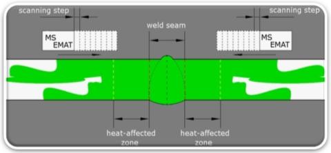
Weld integrity is a crucial component of pipeline safety, especially girth welds (or the circumferential welds that join each section of pipe together). However, unlike the consistent molecular structure of milled steel, welds and their heat-affected zones (HAZs) have an anisotropic grain structure that attenuates ultrasonic signals and creates wave velocity variances that are difficult for ILI tools to analyze.
One angle-beam EMAT method employs a set of nine frequency-time (FT) scans on each side of the girth weld, where each frequency corresponds to a different input wave angle.[2] The following figure shows a diagram of the inspection area covered by this method, where the green area represents the propagation of shear waves in the weld and surrounding metal.
The principle of angle-beam EMAT use in pipeline girth weld assessment.The frequency-time matrix for a lateral cylindrical hole in a pipe
The tool merges each set of FT scans into a single frequency-time matrix scan to display weld conditions, with anomalies color-coded by severity.[2] This method of girth weld scanning is designed to detect the following weld defects:
Magnetic flux leakage (MFL) tools use a sensor sandwiched between multiple powerful magnets to create and measure the flow of magnetic flux in the pipe wall. Structurally-sound steel has a uniform structure that allows regular flow of the magnetic flux, while anomalies and features interrupt the flow of flux in identifiable patterns; the sensor registers these flow interruptions and records them for later analysis. The following figure illustrates the principle of a typical MFL inspection tool; the left side of the diagram shows how an MFL tool works in structurally sound pipe, while the right side shows how the tool detects and measures a metal loss defect.[3]
The principle of a typical MFL pipeline inspection tool.
MFL tools are used primarily to detect pitting corrosion, and some tool configurations can detect weld defects. One advantage of MFL tools over ultrasonic tools is the ability to maintain reasonable sensitivity through relatively thick surface coatings (e.g., paint, pipe liners).[4]
Video inspection
A high-resolution camera image of an internal corrosion pit in a pipe wall
Robotic NDT tools employ cameras to provide technicians an optimal view of the inspection area. Some cameras provide specific views of the pipeline (e.g., straight forward, sensor contact area on the metal) to assist in controlling the tool, while other cameras are used to take high-resolution photographs of inspection findings.
Some tools exist solely to perform video inspection; many of these tools include a mechanism to aim the camera to completely optimize technicians’ field of vision, and the lack of other bulky ILI sensor packages makes these tools exceptionally maneuverable. Cameras on multipurpose ILI tools are usually placed in locations that maximize technicians’ ability to analyze findings as well as optimally control the tool.
Laser profilometry
Laser profilometry assessment of the pipe wall corrosion pit shown in the previous image
Laser profilometers project a shape onto the object surface. Technicians configure the laser (both angle of incidence and distance from the object) to ensure the shape is uniform on normal metal. Superficial anomalies (e.g., pitting corrosion, dents) distort the shape, allowing the inspection technicians to measure the anomalies using proprietary software programs. Photographs of these laser distortions provide visual evidence that improves the data analysis process and contributes to structural integrity efforts.
Pulsed-eddy current (PEC) tools use a probe coil to send a pulsed magnetic field into a metal object. The varying magnetic field induces eddy currents on the metal surface. The tool processes the detected eddy current signal and compares it to a reference signal set before the tool run; the material properties are eliminated to give a reading for the average wall thickness within the area covered by the magnetic field. The tool logs the signal for later analysis.[5] The following diagram illustrates the principle of a typical PEC inspection tool.
PEC tool operating principle.
PEC tools can inspect accurately with a larger gap between the transducer and the inspection object than other tools, making it ideal for inspecting metal through non-metal substances (e.g., pipe coatings, insulation, marine growth).
Case studies
United States federal law requires baseline inspections to establish pipeline as-built statistics and subsequent periodic inspections to monitor asset deterioration. Pipeline operators also are responsible to designate high-consequence areas (HCAs) in all pipelines, perform regular assessments to monitor pipeline conditions, and develop preventive actions and response plans.[6]
State regulations for inspecting pipelines vary based on the level of public safety concerns. For example, a 2010 natural gas pipeline explosion in a San Bruno residential neighborhood led the California Public Utilities Commission to require safety enhancement plans from California natural gas transmission operators.[7] The safety plan included numerous pipeline replacements and in-line inspections.
Tethered robotic ILI crawler application examples
The federal Pipeline and Hazardous Materials Safety Administration (PHMSA) does not permit use of tetherless crawlers in HCAs due to the risk of getting stuck. Excavating buried pipelines to retrieve stuck tools beneath freeway crossings, river crossings or dense urban areas would impact the community infrastructure too greatly. Natural gas and oil pipeline operators therefore rely on tethered robotic ILI crawlers to inspect unpiggable pipelines.
Williams used a tethered robotic ILI crawler to inspect an unpiggable section of the Transco Pipeline in New Jersey in 2015.[8] The pipeline system ran beneath the Hudson River; construction of a new condominium development nearby created a new HCA, requiring Williams to create an integrity management program per PHMSA regulations.
Alyeska Pipeline Service Company inspected Pump Station 3 on the Trans-Alaska Pipeline System after an oil leak was discovered in an underground oil pipeline at Pump Station 1 in 2011.[9] The spill resulted in a consent agreement between Alyeska and PHMSA requiring Alyeska to remove all liquid-transport piping from its system that could not be assessed using ILI tools or a similar suitable inspection technique. Because other ILI tools could not navigate the pipeline geometry common to each of the eleven pump stations along the pipeline, Alyeska received approval to use a tethered robotic ILI crawler manufactured by Diakont to complete an inspection project at Pump Station 3. This tool allowed Alyeska to only remove a few small aboveground fittings to permit crawler entry into the piping, saving the time and expense necessary to excavate hundreds of feet of pipe (some of which was also encased in concrete vaults) to inspect by hand.
Nuclear power plants in the United States are subject to unique integrity management mandates per the Nuclear Energy Institute (NEI) NEI 09-14, Guideline for the Management of Buried Piping Integrity.
The Cooper Nuclear Station in Nebraska performed buried pipe inspections to comply with these industry mandates as part of a 2010 nuclear power plant license renewal. Part of the plant pipeline integrity management program included inspecting a high pressure coolant injection (HPCI) line using a tethered robotic ILI crawler manufactured by Diakont.[10]
Tetherless robotic ILI crawler application examples
Natural gas pipeline operators can use tetherless robotic ILI crawlers for smaller distribution pipelines that are not located beneath critical infrastructure elements (e.g., freeway crossings).
In 2011, Southern California Gas Company (SoCalGas) used a tetherless robotic ILI crawler manufactured by Pipetel to inspect an 8” natural gas pipeline whose product flow lacked the pressure to propel a traditional smart pig. The tool successfully inspected 2.5 miles of pipeline, including a cased segment and an area underneath a railway track.[12]
Southwest Gas Corporation used the same tool in 2013 to inspect approximately one mile of a 6” natural gas line in Las Vegas, Nevada.[13]
Central Hudson Gas & Electric used a similar crawler in 2015 to inspect a 3000’ section of a 16” natural gas line that included a roadway crossing.[14]
NDT method comparison
Robotic NDT tools have the following advantages over other NDT methods:
Real-time data analysis makes structural integrity efforts more effective and convenient.
Faster preliminary results make structural integrity management more efficient – results from a smart pig are not available until the tool run is complete and may take up to 90 days to analyze, whereas the shorter inspection scope and close real-time monitoring allow robotic tool results to be formally reported in as little as 30 days.
Robotic tools inspections can include an immediate reporting threshold.
Crews can use the separate reporting thresholds to better prioritize findings.
The ability to stop the tool and alert customer engineers to the most serious findings helps expedite structural integrity efforts.
Continuous monitoring allows for tool repair or/and inspection scope adjustment to prevent the cost/inconvenience of a whole repeat tool run.
Real-time data monitoring allows daily reports and makes a preliminary report (containing only the most serious anomalies) possible.
The inspection crew can stop the tool’s forward progress to re-examine findings in order to gather additional data and confirm defect identity/severity.
The ability to monitor tool function ensures tool data integrity for the entirety of the inspection.
The compact footprint of these tools allows them to be deployed at customer convenience rather than limited to pre-established endpoints (i.e., pig launcher/receiver).
This makes tethered tools less likely to get stuck, and easier to retrieve if stuck/damaged.
Pipeline operators can enjoy major savings on excavation costs when examining underground installations, especially if the tool run can be coordinated with an existing excavation during other maintenance efforts.
The smaller space requirements make robotic NDT crawlers much easier to use in urban environments and other cramped settings where pedestrians, vehicular traffic, and/or other workers are present.
Robotic NDT tools are specifically designed to navigate more complex environments.
The inspection crew can adapt tool travel to accommodate fixtures (e.g., tees, bends, tank roof supports) as well as findings (e.g., dents, corrosion pits) to prevent the tool from becoming damaged or stuck.
The inspection crew can also manipulate the tool to maximize sensor reception in areas where the tool’s normal travel path would impact readings.
Many inspection areas pose significant safety hazards to human occupants that can be eliminated or greatly reduced by robotic NDT tools:
The modest entry requirements and remote operation of pipeline inspection crawlers minimizes hazards associated with working in trenches.
Robotic inspection inside liquid tanks eliminates the hazards associated with working in confined spaces, especially if the tank contents include dangerous fumes.
Robotic inspection of tank shells eliminates the need for fall protection and the dangers involved with working at significant heights.
The cost of an outage for an inspection (and planned maintenance, if necessary) is a fraction of the costs involved in an asset failure.
Robotic tools have the following disadvantages against other NDT methods:
The need for the inspection crew to maintain communication with the tool limits its effective range.
Tethered tools may also be limited by the crawler’s ability to pull the tether over long distances.
Tension on a tethered crawler’s cable may limit tool movement after passing too many bends in pipeline applications, or after wrapping around roof supports during tank floor inspections.
Many self-propelled pipeline inspection tools are slower than pigs that can flow with product.
Unlike some remote-control vehicles that are commercially available for rent or sale, robotic NDT crawlers require significant training before they can be used for formal inspection.
Many crawlers require the inspection area to be taken out of service and cleaned before operations.
Continuous air-quality monitoring may be necessary during operations, up to provision of a blanket of inert gas (e.g., nitrogen) if the area contains especially flammable/explosive fumes.
Loose debris (e.g., ferromagnetic dust, paraffin) or internal corrosion can impact EMAT and MFL readings.
These services can often be performed during scheduled outages, but special shut-down may be necessary if regulatory requirements do not align with other planned service outages.
References
12Ultrasonic Testing. The Hashemite University NDT Center. Accessed 2 March 2016.
This page is based on this Wikipedia article Text is available under the CC BY-SA 4.0 license; additional terms may apply. Images, videos and audio are available under their respective licenses.