Most servos are rotary actuators although other types are available. Linear actuators are sometimes used, although it is more common to use a rotary actuator with a bellcrank and pushrod. Some types, originally used as sailwinches for model yachting, can rotate continuously.
Construction
Internal mechanism of a continuous rotation servo
A typical servo consists of a small electric motor driving a train of reduction gears. A potentiometer is connected to the output shaft. Some simple electronics provide a closed-loopservomechanism.
Operation
The position of the output, measured by the potentiometer, is continually compared to the commanded position from the control (i.e., the radio control). Any difference gives rise to an error signal in the appropriate direction, which drives the electric motor either forwards or backwards, and moving the output shaft to the commanded position. When the servo reaches this position, the error signal reduces and then becomes zero, at which point the servo stops moving.
If the servo position changes from that commanded, whether this is because the command changes, or because the servo is mechanically pushed from its set position, the error signal will re-appear and cause the motor to restore the servo output shaft to the position needed.
Almost all modern servos are proportional servos, where this commanded position can be anywhere within the range of movement. Early servos, and a precursor device called an escapement, could only move to a limited number of set positions.
Radio control servos are connected through a standard three-wire connection: two wires for a DC power supply and one for control, carrying a pulse-width modulation (PWM) signal. Each servo has a separate connection and PWM signal from the radio control receiver. This signal is easily generated by simple electronics, or by microcontrollers such as the Arduino. This, together with their low cost, has led to their wide adoption for robotics and physical computing.
RC servos use a three-pin 0.1"-spacing jack (female) which mates to standard 0.025" square pins. The most common order is signal, +voltage, ground. The standard voltage is 4.8 V DC, however 6 V and 12 V is also used on a few servos. The control signal is a digital PWM signal with a 50Hz frame rate. Within each 20 ms timeframe, an active-high digital pulse controls the position. The pulse nominally ranges from 1.0 ms to 2.0 ms with 1.5 ms always being center of range. Pulse widths outside this range can be used for "overtravel" - moving the servo beyond its normal range.
There are two general types of PWM. Each PWM defines a value that is used by the servo to determine its expected position. The first type is "absolute" and defines the value by the width of the active-high time pulse with an arbitrarily long period of low time. The second type is "relative" and defines the value by the percentage of time the control is active-high versus low-time. The "absolute" type allows up to eight servos to share one communication channel by multiplexing control signals using relatively simple electronics and is the basis of modern RC servos. The "relative" type is the more traditional usage of PWM whereby a simple low-pass filter converts a "relative" PWM signal into an analog voltage. The two types are both PWM because the servo responds to the width of the pulse. However, in the first case a servo may also be sensitive to pulse order.
The servo is controlled by three wires: ground, power, and control. The servo will move based on the pulses sent over the control wire, which set the angle of the actuator arm. The servo expects a pulse every 20 ms in order to gain correct information about the angle. The width of the servo pulse dictates the range of the servo's angular motion.
A servo pulse of 1.5 ms width will typically set the servo to its "neutral" position (typically half of the specified full range), a pulse of 1.0 ms will set it to 0°, and a pulse of 2.0 ms to 90° (for a 90° servo). The physical limits and timings of the servo hardware varies between brands and models, but a general servo's full angular motion will travel somewhere in the range of 90° – 180° and the neutral position (45° or 90°) is almost always at 1.5 ms. This is the "standard pulse servo mode" used by all hobby analog servos.
A hobby digital servo is controlled by the same "standard pulse servo mode" pulses as an analog servo.[1] Some hobby digital servos can be set to another mode that allows a robot controller to read back the actual position of the servo shaft. Some hobby digital servos can optionally be set to another mode and "programmed", so it has the desired PID controller characteristics when it is later driven by a standard RC receiver.[2]
Manufacturers and distributors of hobby RC servos often use a specific shorthand notation of mechanical properties of the servos. Two figures are typically stated: angular speed of servo shaft rotation and mechanical torque produced on the shaft. Speed is expressed as a time interval that a servo requires in order to rotate the shaft through a 60° angle. Torque is expressed as weight that can be pulled up by the servo if it hangs from a pulley with a certain radius mounted on the shaft.
For example, if a servo model is described as "0.2s / 2kg", that should be interpreted as "This servo rotates the shaft for 60° in 0.2seconds, and it is able to pull up a 2kg weight using a 1cm radius pulley". That is, that particular servo model rotates the shaft with the angular speed of (2π / 6) / 0.2s = 5.2rad/s while producing 2kg × 9.81m/s2 = 19.6N force at 1cm distance, i.e., it produces 19.6N × 0.01m = 0.196Nm torque.
Although not in accordance with either the SI or Imperial unit system, the shorthand notation is in fact quite useful, as 60° shaft rotation commands, 1cm long shaft cranks, as well as control rod "forces" in kilogram-force range are typical in hobby RC world.
Continuous-rotation servos
Continuous-rotation servos are servos that do not have a limited travel angle, instead they can rotate continuously. They can be thought of as a motor and gearbox with servo input controls. In such servos the input pulse results in a rotational speed, and the typical 1.5ms center value is the stop position. A smaller value should turn the servo clockwise and a higher one counterclockwise.
Escapements
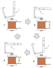
Escapement operating sequence
The earliest form of sequential (although not proportional) actuator for radio control was the escapement.[3] Like the device used in clocks, this escapement controls the release of stored energy from a spring or rubber band. Each signal from the transmitter operates a small solenoid that then allows a two- or four-lobed pawl to rotate. The pawl, like a clock, has two pallets so that the pawl can only rotate by one lobe's position, per signal pulse. This mechanism allows a simple keyed transmitter to give sequential control, i.e. selection between a number of defined positions at the model.
A typical four-lobe escapement used for rudder control is arranged so that the first and third positions are "straight ahead", with positions two and four as "left" and "right" rudder. A single pulse from the first straight-ahead position allows it to move to left, or three pulses would select right. A further single pulse returns to straight-ahead.[4] Such a system is difficult to use, as it requires the operator to remember which position the escapement is in, and so whether the next turn requires one or three pulses from the current position. A development of this was the two-lobe pawl, where keying the transmitter continuously (and thus holding the solenoid pallet in place) could be used to select the turn positions with the same keying sequence, no matter what the previous position.[4]
Escapements were low-powered, but light-weight. They were thus more popular for model aircraft than model boats.[3] Where a transmitter and receiver had multiple control channels (e.g., a frequency-keyed reed receiver), then multiple escapements could be used together, one for each channel.[3] Even with single channel radios, a sequence of escapements could sometimes be cascaded. Moving one escapement gave pulses that in turn drove a second, slower speed, escapement.[4] Escapements were disappearing from radio control, in favour of servos, by the early 1970s.[3]
Graupner 'Kinematic' escapement for model boat rudder control, circa 1965
The Graupner Kinematic escapement could be used for rudder and electric motor control with one channel. Short pulses for the motor; forward - stop - reverse - stop etc. and long pulses for the rudder; straight ahead - turn left - straight ahead - turn right - straight ahead etc.
Centrifugal fly-ball actuator
Centrifugal fly-ball actuator
The fly-ball actuator was introduced to R/C modelling in 1951 by Brayton Paul,[5] and consisted of an electric motor and a centrifugal governor connected to a free-running axis that could, with the motor running, pull a rudder control rod by varying degrees. Used with a keyed radio system, this allowed some control over the rudder position by varying the key push timing. The rudder would be pulled back by a spring when the motor speed decreased.
Pulse-width modulation (PWM), also known as pulse-duration modulation (PDM) or pulse-length modulation (PLM), is any method of representing a signal as a rectangular wave with a varying duty cycle.
A model aircraft is a physical model of an existing or imagined aircraft, and is built typically for display, research, or amusement. Model aircraft are divided into two basic groups: flying and non-flying. Non-flying models are also termed static, display, or shelf models.
Radio-controlled cars, or RC cars for short, are miniature model cars, vans, buses, trucks or buggies that can be controlled from a distance using a specialized transmitter or remote. The term "RC" has been used to mean both "remote controlled" and "radio-controlled". "Remote controlled" includes vehicles that are controlled by radio waves, infrared waves or a physical wire connection. RC cars are powered by one of the three energy sources—electricity, nitro fuel or petrol. Electric RC models are powered by small but powerful electric motors and rechargeable nickel-cadmium (Ni-Cd), nickel metal hydride(NiMH), or lithium polymer (LiPo) cells with the former two being the most used. Both NiMH and LiPo have advantages and disadvantages in various RC applications where NiMH is mainly used for recreational and LiPo for more demanding purposes. There are also brushed or brushless electric motors—brushless motors are more powerful, long lasting and efficient, but also much more expensive than brushed motors.
A radio-controlled model is a model that is steerable with the use of radio control (RC). All types of model vehicles have had RC systems installed in them, including ground vehicles, boats, planes, helicopters and even submarines and scale railway locomotives.
Pulse-position modulation (PPM) is a form of signal modulation in which M message bits are encoded by transmitting a single pulse in one of possible required time shifts. This is repeated every T seconds, such that the transmitted bit rate is bits per second. It is primarily useful for optical communications systems, which tend to have little or no multipath interference.
A stepper motor, also known as step motor or stepping motor, is an electrical motor that rotates in a series of small angular steps, instead of continuously. Stepper motors are a type of digital actuator. Like other electromagnetic actuators, they convert electric energy into mechanical position can be commanded to move and hold at one of these steps without any position sensor for feedback, as long as the motor is correctly sized to the application in respect to torque and speed.
Radio control is the use of control signals transmitted by radio to remotely operate a device. Examples of simple radio control systems are garage door openers and keyless entry systems for vehicles, in which a small handheld radio transmitter unlocks or opens doors. Radio control is also used for control of model vehicles from a hand-held radio transmitter. Industrial, military, and scientific research organizations make use of radio-controlled vehicles as well. A rapidly growing application is control of unmanned aerial vehicles for both civilian and military uses, although these have more sophisticated control systems than traditional applications.
In mechanical and control engineering, a servomechanism is a control system for the position and its time derivatives, such as velocity, of a mechanical system. It often includes a servomotor, and uses closed-loop control to reduce steady-state error and improve dynamic response. In closed-loop control, error-sensing negative feedback is used to correct the action of the mechanism. In displacement-controlled applications, it usually includes a built-in encoder or other position feedback mechanism to ensure the output is achieving the desired effect. Following a specified motion trajectory is called servoing, where "servo" is used as a verb. The servo prefix originates from the Latin word servus meaning slave.
A brushless DC electric motor (BLDC), also known as an electronically commutated motor, is a synchronous motor using a direct current (DC) electric power supply. It uses an electronic controller to switch DC currents to the motor windings producing magnetic fields that effectively rotate in space and which the permanent magnet rotor follows. The controller adjusts the phase and amplitude of the current pulses that control the speed and torque of the motor. It is an improvement on the mechanical commutator (brushes) used in many conventional electric motors.
A rotary encoder, also called a shaft encoder, is an electro-mechanical device that converts the angular position or motion of a shaft or axle to analog or digital output signals.
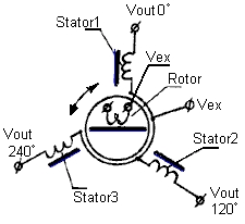
A synchro is, in effect, a transformer whose primary-to-secondary coupling may be varied by physically changing the relative orientation of the two windings. Synchros are often used for measuring the angle of a rotating machine such as an antenna platform or transmitting rotation. In its general physical construction, it is much like an electric motor. The primary winding of the transformer, fixed to the rotor, is excited by an alternating current, which by electromagnetic induction causes voltages to appear between the Y-connected secondary windings fixed at 120 degrees to each other on the stator. The voltages are measured and used to determine the angle of the rotor relative to the stator.
A radio-controlled aircraft is a small flying machine that is radio controlled by an operator on the ground using a hand-held radio transmitter. The transmitter continuously communicates with a receiver within the craft that sends signals to servomechanisms (servos) which move the control surfaces based on the position of joysticks on the transmitter. The control surfaces, in turn, directly affect the orientation of the plane.
An electronic speed control (ESC) is an electronic circuit that controls and regulates the speed of an electric motor. It may also provide reversing of the motor and dynamic braking. Miniature electronic speed controls are used in electrically powered radio controlled models. Full-size electric vehicles also have systems to control the speed of their drive motors.
A servomotor is a rotary or linear actuator that allows for precise control of angular or linear position, velocity, and acceleration in a mechanical system. It constitutes part of a servomechanism, and consists of a suitable motor coupled to a sensor for position feedback and a controller.
A radio-controlled boat is a boat or ship model controlled remotely with radio control equipment.
A servo drive is an electronic amplifier used to power electric servomechanisms.
The Tamiya TXT-1, which stands for Tamiya eXtreme Truck, was one of Tamiya's 1/10 scale radio controlled (RC) Monster Trucks.
Servo control is a method of controlling many types of RC/hobbyist servos by sending the servo a PWM signal, a series of repeating pulses of variable width where either the width of the pulse or the duty cycle of a pulse train determines the position to be achieved by the servo. The PWM signal might come from a radio control receiver to the servo or from common microcontrollers such as the Arduino.
A rotary actuator is an actuator that produces a rotary motion or torque.
A reed receiver or tuned reed receiver (US) was a form of multi-channel signal decoder used for early radio control systems. It uses a simple electromechanical device or 'resonant reed' to demodulate the signal, in effect a receive-only modem. The encoding used is a simple form of frequency-shift keying.
This page is based on this Wikipedia article Text is available under the CC BY-SA 4.0 license; additional terms may apply. Images, videos and audio are available under their respective licenses.