Related Research Articles

In telecommunications, a collinear antenna array is an array of dipole or quarter-wave antennas mounted in such a manner that the corresponding elements of each antenna are parallel and collinear; that is, they are located along a common axis.

A log-periodic antenna (LP), also known as a log-periodic array or log-periodic aerial, is a multi-element, directional antenna designed to operate over a wide band of frequencies. It was invented by John Dunlavy in 1952.

In a radio antenna's radiation pattern, the main lobe, or main beam, is the lobe containing the higher power. This is the lobe that exhibits the greater field strength.

In telecommunications and radar, a reflective array antenna is a class of directive antennas in which multiple driven elements are mounted in front of a flat surface designed to reflect the radio waves in a desired direction. They are a type of array antenna. They are often used in the VHF and UHF frequency bands. VHF examples are generally large and resemble a highway billboard, so they are sometimes called billboard antennas. Other names are bedspring array and bowtie array depending on the type of elements making up the antenna. The curtain array is a larger version used by shortwave radio broadcasting stations.

In radio engineering, an antenna or aerial is the interface between radio waves propagating through space and electric currents moving in metal conductors, used with a transmitter or receiver. In transmission, a radio transmitter supplies an electric current to the antenna's terminals, and the antenna radiates the energy from the current as electromagnetic waves. In reception, an antenna intercepts some of the power of a radio wave in order to produce an electric current at its terminals, that is applied to a receiver to be amplified. Antennas are essential components of all radio equipment.

Effective radiated power (ERP), synonymous with equivalent radiated power, is an IEEE standardized definition of directional radio frequency (RF) power, such as that emitted by a radio transmitter. It is the total power in watts that would have to be radiated by a half-wave dipole antenna to give the same radiation intensity as the actual source antenna at a distant receiver located in the direction of the antenna's strongest beam. ERP measures the combination of the power emitted by the transmitter and the ability of the antenna to direct that power in a given direction. It is equal to the input power to the antenna multiplied by the gain of the antenna. It is used in electronics and telecommunications, particularly in broadcasting to quantify the apparent power of a broadcasting station experienced by listeners in its reception area.

A helical antenna is an antenna consisting of one or more conducting wires wound in the form of a helix. A helical antenna made of one helical wire, the most common type, is called monofilar, while antennas with two or four wires in a helix are called bifilar, or quadrifilar, respectively.

A whip antenna is an antenna consisting of a straight flexible wire or rod. The bottom end of the whip is connected to the radio receiver or transmitter. The antenna is designed to be flexible so that it does not break easily, and the name is derived from the whip-like motion that it exhibits when disturbed. Whip antennas for portable radios are often made of a series of interlocking telescoping metal tubes, so they can be retracted when not in use. Longer ones, made for mounting on vehicles and structures, are made of a flexible fiberglass rod around a wire core and can be up to 35 ft long. The length of the whip antenna is determined by the wavelength of the radio waves it is used with. The most common type is the quarter-wave whip, which is approximately one-quarter of a wavelength long. Whips are the most common type of monopole antenna, and are used in the higher frequency HF, VHF and UHF radio bands. They are widely used as the antennas for hand-held radios, cordless phones, walkie-talkies, FM radios, boom boxes, and Wi-Fi enabled devices, and are attached to vehicles as the antennas for car radios and two-way radios for wheeled vehicles and for aircraft. Larger versions mounted on roofs, balconies and radio masts are used as base station antennas for amateur radio and police, fire, ambulance, taxi, and other vehicle dispatchers.

A slot antenna consists of a metal surface, usually a flat plate, with one or more holes or slots cut out. When the plate is driven as an antenna by an applied radio frequency current, the slot radiates electromagnetic waves in a way similar to a dipole antenna. The shape and size of the slot, as well as the driving frequency, determine the radiation pattern. Slot antennas are usually used at UHF and microwave frequencies at which wavelengths are small enough that the plate and slot are conveniently small. At these frequencies, the radio waves are often conducted by a waveguide, and the antenna consists of slots in the waveguide; this is called a slotted waveguide antenna. Multiple slots act as a directive array antenna and can emit a narrow fan-shaped beam of microwaves. They are used in standard laboratory microwave sources used for research, UHF television transmitting antennas, antennas on missiles and aircraft, sector antennas for cellular base stations, and particularly marine radar antennas. A slot antenna's main advantages are its size, design simplicity, and convenient adaptation to mass production using either waveguide or PC board technology.
A broadcast transmitter is an electronic device which radiates radio waves modulated with information content intended to be received by the general public. Examples are a radio broadcasting transmitter which transmits audio (sound) to broadcast radio receivers (radios) owned by the public, or a television transmitter, which transmits moving images (video) to television receivers (televisions). The term often includes the antenna which radiates the radio waves, and the building and facilities associated with the transmitter. A broadcasting station consists of a broadcast transmitter along with the production studio which originates the broadcasts. Broadcast transmitters must be licensed by governments, and are restricted to specific frequencies and power levels. Each transmitter is assigned a unique identifier consisting of a string of letters and numbers called a callsign, which must be used in all broadcasts.
A loop antenna is a radio antenna consisting of a loop or coil of wire, tubing receiving predominantly the magnetic component of the electromagnetic wave, or other electrical conductor usually fed by a balanced source or feeding a balanced load. Within this physical description there are two distinct antenna types:

A television antenna is an antenna specifically designed for use with a television receiver (TV) to receive over-the-air broadcast television signals from a television station. Terrestrial television is broadcast on frequencies from about 47 to 250 MHz in the very high frequency (VHF) band, and 470 to 960 MHz in the ultra high frequency (UHF) band in different countries. Television antennas are manufactured in two different types: "indoor" antennas, to be located on top of or next to the television set, and "outdoor" antennas, mounted on a mast on top of the owner's house. They can also be mounted in a loft or attic, where the dry conditions and increased elevation are advantageous for reception and antenna longevity. Outdoor antennas are more expensive and difficult to install, but are necessary for adequate reception in fringe areas far from television stations. The most common types of indoor antennas are the dipole and loop antennas, and for outdoor antennas the yagi, log periodic, and for UHF channels the multi-bay reflective array antenna.

A monopole antenna is a class of radio antenna consisting of a straight rod-shaped conductor, often mounted perpendicularly over some type of conductive surface, called a ground plane. The driving signal from the transmitter is applied, or for receiving antennas the output signal to the receiver is taken, between the lower end of the monopole and the ground plane. One side of the antenna feedline is attached to the lower end of the monopole, and the other side is attached to the ground plane, which is often the Earth. This contrasts with a dipole antenna which consists of two identical rod conductors, with the signal from the transmitter applied between the two halves of the antenna.

A turnstile antenna, or crossed-dipole antenna, is a radio antenna consisting of a set of two identical dipole antennas mounted at right angles to each other and fed in phase quadrature; the two currents applied to the dipoles are 90° out of phase. The name reflects the notion the antenna looks like a turnstile when mounted horizontally. The antenna can be used in two possible modes. In normal mode the antenna radiates horizontally polarized radio waves perpendicular to its axis. In axial mode the antenna radiates circularly polarized radiation along its axis.

A transmitter station or transmission facility is an installation used for transmitting radio frequency signals for wireless communication, broadcasting, microwave link, mobile telephone or other purposes.

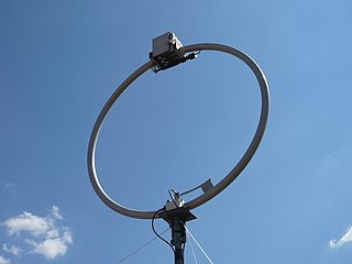
A halo antenna, or halo, is a 1⁄2 wavelength dipole antenna, which has been bent into a circle with an electrical break directly opposite the feed point. The dipole ends are close but do not meet, and may have an air capacitor between them to adjust the antenna's resonant frequency. If mounted horizontally, this antenna's radiation is approximately omnidirectional and horizontally polarized.
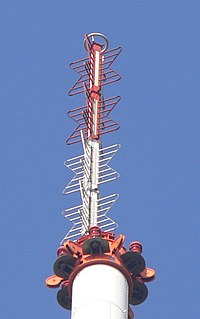
A batwing or super turnstile antenna is a type of broadcasting antenna used at VHF and UHF frequencies, named for its distinctive shape which resembles a bat wing or bow tie. Stacked arrays of batwing antennas are used as television broadcasting antennas due to their omnidirectional characteristics. Batwing antennas generate a horizontally polarized signal. The advantage of the "batwing" design for television broadcasting is that it has a wide bandwidth. It was the first widely used television broadcasting antenna.
An antenna array is a set of multiple connected antennas which work together as a single antenna, to transmit or receive radio waves. The individual antennas are usually connected to a single receiver or transmitter by feedlines that feed the power to the elements in a specific phase relationship. The radio waves radiated by each individual antenna combine and superpose, adding together to enhance the power radiated in desired directions, and cancelling to reduce the power radiated in other directions. Similarly, when used for receiving, the separate radio frequency currents from the individual antennas combine in the receiver with the correct phase relationship to enhance signals received from the desired directions and cancel signals from undesired directions. More sophisticated array antennas may have multiple transmitter or receiver modules, each connected to a separate antenna element or group of elements.
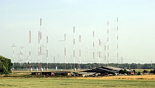
Curtain arrays are a class of large multielement directional wire radio transmitting antennas, used in the shortwave radio bands. They are a type of reflective array antenna, consisting of multiple wire dipole antennas, suspended in a vertical plane, often in front of a "curtain" reflector made of a flat vertical screen of many long parallel wires. These are suspended by support wires strung between pairs of tall steel towers, up to 300 ft (90 m) high. They are used for long-distance skywave transmission; they transmit a beam of radio waves at a shallow angle into the sky just above the horizon, which is reflected by the ionosphere back to Earth beyond the horizon. Curtain antennas are mostly used by international short wave radio stations to broadcast to large areas at transcontinental distances.
In radio systems, many different antenna types are used with specialized properties for particular applications. Antennas can be classified in various ways. The list below groups together antennas under common operating principles, following the way antennas are classified in many engineering textbooks.
References
- ↑ R.Busi: High altitude VHF and UHF Broadcasting stations, EBU technical center, Brussels, 1967 p 25