Vortex lift

Last updated
Image showing formation of vortices behind the leading edge of a delta wing at high angle of attack Vortex lift.gif
Image showing formation of vortices behind the leading edge of a delta wing at high angle of attack
A cloud of smoke shows the roll-up of the vortex sheet shed from the whole trailing edge of a wing producing lift from attached flow, with its core aligned with the wing tip. Vortex lift has an additional vortex close to the body when shed by a leading edge root extension or closer to the tip when shed by a sweptback leading edge. Airplane vortex edit.jpg
A cloud of smoke shows the roll-up of the vortex sheet shed from the whole trailing edge of a wing producing lift from attached flow, with its core aligned with the wing tip. Vortex lift has an additional vortex close to the body when shed by a leading edge root extension or closer to the tip when shed by a sweptback leading edge.

Vortex lift is that portion of lift due to the action of leading edge vortices. [1] It is generated by wings with highly sweptback, sharp, leading edges (beyond 50 degrees of sweep) or highly-swept wing-root extensions added to a wing of moderate sweep. [2] It is sometimes known as non-linear lift due to its rapid increase with angle of attack. [3] and controlled separation lift, to distinguish it from conventional lift which occurs with attached flow.
Contents

How it works

Vortex lift works by capturing vortices generated from the sharply swept leading edge of the wing. The vortex, formed roughly parallel to the leading edge of the wing, is trapped by the airflow and remains fixed to the upper surface of the wing. As the air flows around the leading edge, it flows over the trapped vortex and is pulled in and down to generate the lift.

A straight, or moderate sweep, wing may experience, depending on its airfoil section, a leading-edge stall and loss of lift, as a result of flow separation at the leading edge [4] and a non-lifting wake over the top of the wing. However, on a highly-swept wing leading-edge separation still occurs but instead creates a vortex sheet that rolls up above the wing producing spanwise flow beneath. Flow not entrained by the vortex passes over the top of the vortex and reattaches to the wing surface. [5] The vortex generates a high negative pressure field on the top of the wing. Vortex lift increases with angle of attack (AOA) as seen on lift~AOA plots which show the vortex, or unattached flow, adding to the normal attached lift as an extra non-linear component of the overall lift. [6] Vortex lift has a limiting AoA at which the vortex bursts or breaks down.

Applications

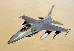
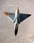
Four basic configurations which have used vortex lift are, in chronological order, the 60-degree delta wing; the ogive delta wing with its sharply-swept leading edge at the root; the moderately-swept wing with a leading-edge extension, which is known as a hybrid wing; and the sharp-edge forebody, or vortex-lift strake. [7] Wings which generate vortex lift have been used on delta-winged research aircraft such as the Convair XF-92A and Fairey Delta 2. Early delta wing fighters such as the F-102, the F-106, and contemporaries such as Dassault's deltas had cambered leading edges that were blunt and did not generate significant vortexes. The Concorde supersonic airliner had sharp leading edges. Wings with vortex lift over the inboard section are the moderate-sweep wings with an easily identified LERX used on high-manoeuvrability combat aircraft, such as the Northrop F-5 and McDonnell Douglas F/A-18 Hornet. Vortex lift sharp forebody strakes are used on the General Dynamics F-16 Fighting Falcon.

Benefits and shortcomings

Vortex lift provides high lift with increasing AoA at landing speeds and in manoeuvring flight. A high AoA needed to meet landing requirements has, in the past, restricted pilot visibility and led to design complications to accommodate a drooping nose, as in the case of the Fairey Delta 2 and Concorde. For moderate swept wings the addition of a LERX reduces wave drag and improves turning performance and enables a far wider range of flying attitudes. [8] The use of vortex lift is restricted by vortex breakdown or bursting and an inherent instability in yaw. There is considerable drag due to increased lift production and loss of leading edge suction that is part of normal attached flow round a leading edge. [9]

Among animals

Animals such as hummingbirds, and bats that eat pollen and nectar, are able to hover. They produce vortex lift with the sharp leading edges of their wings and change their wing shapes and curvatures to create stability in the lift. [10]

See also

Related Research Articles

<span class="mw-page-title-main">Wing</span> Appendage used for flight

A wing is a type of fin that produces lift while moving through air or some other fluid. Accordingly, wings have streamlined cross-sections that are subject to aerodynamic forces and act as airfoils. A wing's aerodynamic efficiency is expressed as its lift-to-drag ratio. The lift a wing generates at a given speed and angle of attack can be one to two orders of magnitude greater than the total drag on the wing. A high lift-to-drag ratio requires a significantly smaller thrust to propel the wings through the air at sufficient lift.

<span class="mw-page-title-main">Area rule</span> Aerodynamic concept

The Whitcomb area rule, named after NACA engineer Richard Whitcomb and also called the transonic area rule, is a design procedure used to reduce an aircraft's drag at transonic speeds which occur between about Mach 0.75 and 1.2. For supersonic speeds a different procedure called the supersonic area rule, developed by NACA aerodynamicist Robert Jones, is used.

<span class="mw-page-title-main">Stall (fluid dynamics)</span> Abrupt reduction in lift due to flow separation

In fluid dynamics, a stall is a reduction in the lift coefficient generated by a foil as angle of attack increases. This occurs when the critical angle of attack of the foil is exceeded. The critical angle of attack is typically about 15°, but it may vary significantly depending on the fluid, foil, and Reynolds number.

<span class="mw-page-title-main">Delta wing</span> Triangle shaped aircraft wing configuration

A delta wing is a wing shaped in the form of a triangle. It is named for its similarity in shape to the Greek uppercase letter delta (Δ).

<span class="mw-page-title-main">Leading-edge extension</span> Anti-stall control surface on aircraft

A leading-edge extension (LEX) is a small extension to an aircraft wing surface, forward of the leading edge. The primary reason for adding an extension is to improve the airflow at high angles of attack and low airspeeds, to improve handling and delay the stall. A dog tooth can also improve airflow and reduce drag at higher speeds.

<span class="mw-page-title-main">Swept wing</span> Plane wing that angles backwards or forwards

A swept wing is a wing angled either backward or occasionally forward from its root rather than perpendicular to the fuselage.

<span class="mw-page-title-main">Lockheed L-2000</span> Proposed US supersonic airliner design

The Lockheed L-2000 was Lockheed Corporation's entry in a government-funded competition to build the United States' first supersonic airliner in the 1960s. The L-2000 lost the contract to the Boeing 2707, but that competing design was ultimately canceled for political, environmental and economic reasons.

<span class="mw-page-title-main">Airfoil</span> Cross-sectional shape of a wing, blade of a propeller, rotor, or turbine, or sail

An airfoil or aerofoil is a streamlined body that is capable of generating significantly more lift than drag. Wings, sails and propeller blades are examples of airfoils. Foils of similar function designed with water as the working fluid are called hydrofoils.

<span class="mw-page-title-main">High-lift device</span> Wing surface area adjuster, typically for shortening take-off and landing

In aircraft design and aerospace engineering, a high-lift device is a component or mechanism on an aircraft's wing that increases the amount of lift produced by the wing. The device may be a fixed component, or a movable mechanism which is deployed when required. Common movable high-lift devices include wing flaps and slats. Fixed devices include leading-edge slots, leading edge root extensions, and boundary layer control systems.

<span class="mw-page-title-main">Wingtip vortices</span> Turbulence caused by difference in air pressure on either side of wing

Wingtip vortices are circular patterns of rotating air left behind a wing as it generates lift. The name is a misnomer because the cores of the vortices are slightly inboard of the wing tips. Wingtip vortices are sometimes named trailing or lift-induced vortices because they also occur at points other than at the wing tips. Indeed, vorticity is trailed at any point on the wing where the lift varies span-wise ; it eventually rolls up into large vortices near the wingtip, at the edge of flap devices, or at other abrupt changes in wing planform.

<span class="mw-page-title-main">Leading-edge cuff</span> Fixed aerodynamic wing device

A leading-edge cuff is a fixed aerodynamic wing device employed on fixed-wing aircraft to improve the stall and spin characteristics. Cuffs may be either factory-designed or an after-market add-on modification.

<span class="mw-page-title-main">Vertical stabilizer</span> Aircraft component

A vertical stabilizer or tail fin is the static part of the vertical tail of an aircraft. The term is commonly applied to the assembly of both this fixed surface and one or more movable rudders hinged to it. Their role is to provide control, stability and trim in yaw. It is part of the aircraft empennage, specifically of its stabilizers.

Boundary layer control refers to methods of controlling the behaviour of fluid flow boundary layers.

<span class="mw-page-title-main">Lippisch DM-1</span> German single-seat research glider, 1944

The Lippisch DM-1 was a single-seat research glider that was designed and built in Germany from 1944.

The Kutta–Joukowski theorem is a fundamental theorem in aerodynamics used for the calculation of lift of an airfoil translating in a uniform fluid at a constant speed large enough so that the flow seen in the body-fixed frame is steady and unseparated. The theorem relates the lift generated by an airfoil to the speed of the airfoil through the fluid, the density of the fluid and the circulation around the airfoil. The circulation is defined as the line integral around a closed loop enclosing the airfoil of the component of the velocity of the fluid tangent to the loop. It is named after Martin Kutta and Nikolai Zhukovsky who first developed its key ideas in the early 20th century. Kutta–Joukowski theorem is an inviscid theory, but it is a good approximation for real viscous flow in typical aerodynamic applications.

<span class="mw-page-title-main">Handley Page HP.115</span> 1961 experimental aircraft by Handley Page

The Handley Page HP.115 was an experimental delta wing aircraft designed and produced by the British aircraft manufacturer Handley Page. It was built to test the low-speed handling characteristics to be expected from the slender delta configuration anticipated for a future supersonic airliner.

<span class="mw-page-title-main">Wing configuration</span> Describes the general shape and layout of an aircraft wing

The wing configuration of a fixed-wing aircraft is its arrangement of lifting and related surfaces.

<span class="mw-page-title-main">Strake (aeronautics)</span> Flight control surface

In aviation, a strake is an aerodynamic surface generally mounted on the fuselage of an aircraft to improve the flight characteristics either by controlling the airflow or by a simple stabilising effect.

<span class="mw-page-title-main">Vortilon</span> Aerodynamic device

Vortilons are fixed aerodynamic devices on aircraft wings used to improve handling at low speeds.

<span class="mw-page-title-main">Chine (aeronautics)</span> Sharp angle in aircraft cross-sections used as control surface

In aircraft design, a chine is a longitudinal line of sharp change in the cross-section profile of the fuselage or similar body. The term chine originates in boatbuilding, where it applies to a sharp profile change in the hull of a boat. In a flying boat hull or floatplane float, the longitudinal line of sharp change in cross-section where the bottom plane meets the sidewall is an example of a chine.

References

  1. Aircraft Performance and Design, John D. Anderson, Jr., Tata McGraw-Hill Edition 2010, ISBN   978 0 07 070245 5, p.100
  2. "Why's And Wherefore's Of Wings", B.R.A. Burns, Air International magazine, February 1979, p.82
  3. Polhamus, E. C. (December 1966). "NASA Technical Reports Server (NTRS)" (PDF). Ntrs.nasa.gov. Retrieved 2020-11-02.
  4. Design For Air Combat, Ray Whitford 1987, ISBN   0 7106 0426 2, p.16
  5. NASA TM X 2626
  6. Design For Air Combat, Ray Whitford 1987, ISBN   0 7106 0426 2, Fig.81
  7. Design For Air Combat, Ray Whitford 1987, ISBN   0 7106 0426 2, Fig.87
  8. Design For Air Combat, Ray Whitford 1987, ISBN   0 7106 0426 2, p.89-91
  9. "The behaviour and performance of leading-edge Vortex flaps" (PDF). Retrieved 2023-12-17.
  10. "Leading Edge Vortex Allows Bats to Stay Aloft, Aerospace Professor Reports". USC Viterbi School of Engineering. 29 February 2008.