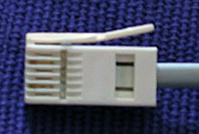
BS 6312 431A plug, colloquially a British Telecom 4-wire male plug
British telephone sockets were introduced in their current plug and socket form on 19 November 1981 by British Telecom to allow subscribers to connect their own telephones. The connectors are specified in British StandardBS 6312.[1][2][3] Electrical characteristics of the telephone interface are specified by individual network operators,[4] e.g. in British Telecom's SIN 351.[5] Electrical characteristics required of British telephones used to be specified in BS 6305.[6]
They are similar to modular connectors (as used in RJ11), but have a side-mounted hook, rather than a bottom-mounted one, and are physically incompatible.
Standard sockets were introduced, as part of the 'New Plan' wiring policy, to allow customers to easily purchase their own telephones, as required by Oftel, the phone regulator. Thus any phone whose plug conformed to BS 6312 and met certain other regulatory standards, such as BABT, could be connected to the network, rather than British Telecom controlling the market. The 'New Plan' was only new to the UK and was based extensively on systems which had been available elsewhere for many years, especially in the US.
The new system replaced the older hard-wired system, which came in many 'flavours' (e.g., Plans 1, 1A, 1B, 1C, 2, 2A, 105, 107 etc.), which could be very complicated and required the attendance at the premises of a GPO telephone-engineer, who needed a complete set of 'N' (wiring) Diagrams,[7][bettersourceneeded] which was very extensive and ran to over 15 volumes of little black ring binders. N diagrams also had their own numbering system (e.g., a Plan 1A had an N diagram of N4502), and were frequently updated.
From the early years of the 1900s, the GPO (subsequently British Telecom) had a plug and socket system available for rent.[8] It was later called a "Plan 4" (N762—first edition), and employed a heavy-duty, four-way jack plug 404 (circular in cross-section), on the end of the standard, plaited, cotton-covered instrument cord. It also had to have a separate bell-set, which was permanently in-circuit to provide ringing if there were no telephones plugged in. This system survived through various models of telephones from the "candlestick" 200 and 300 type Bakelite phones until the introduction of the 700 series in 1959, when a smaller "Plug 420" was introduced. The separate bell-set, with its on-board capacitor and coils, also provided a testing circuit for remote engineers, by providing the mandatory 1000 ohm capacitive loop-back. Rental had to be paid on each telephone and on all the sockets, and hence the system was not that common.
Sockets
A fixed BT Master Socket front LJ 2/1A that does not allow disconnection of internal wiring with previous 1980–1991 BT "T" logo - surface mountedNEW BT NTE5 in 2016BT fibre-to-the-cabinet (FTTC) VDSL faceplate
A domestic single British telephone line installation will have a single master socket or line box in the premises, which is provided by BT or another service provider: this socket is the demarcation point between the customer-owned and maintained on-premises wiring, and the telephone network. For installations using the NTE5 line box (NTE for network termination equipment), the demarcation point is actually within the socket: the lower half of the front plate and associated wiring is the customer's, while the permanent wiring on the non-removable section behind this, remains the responsibility of the service provider. Customers are not permitted to access the wiring in a master socket without a removable lower section. Plug-in extension kits are available for customers with this type of installation. The two wires from the exchange are denoted the B leg at −48V relative to ground when the line is not in use and the A leg which is near ground potential when the line is not in use. The A leg goes to pin 5 and the B leg to pin 2 in the master socket. (Although all equipment will work with a reversed line, so a reverse wired socket is not strictly a fault.) When current is flowing on the line, the B leg voltage collapses to nearer ground and the A leg voltage moves nearer to the B leg voltage. The exact voltage drop is a function of the distance to the exchange, and the network wiring type. According to SIN 352 the average DC current in the loop and voltage across the phone will be up to 42 mA at 12.5 V (short line), up to 33.5 mA at 10 V, and will be not less than 25 mA at 9 V. (long line limit) Line polarity reverses during calls if caller ID is in use.[9] Once in a call the audio and tone levels superimposed on the DC voltage are expressed as dBm in 600 ohms, although the line impedances are permitted to be some way off 600 ohms (as per SIN351) -9 dBm (275 mV RMS) [0 dBm = 1mW ( 0.775V RMS) in 600 ohms.[10]
Until recently,[when?] this socket contained an enclosed spark gap, SP1, that could safely flash over internally to provide high voltage surge protection. This component is no longer used due to negative effects on VDSL speeds. The socket includes a 1.8μF capacitor (bell circuit) to feed the AC ringing and a 470kΩ resistor (R1, out-of-service resistor) to permit remote testing when no telephones are plugged into any sockets. Additional internal extension (secondary) sockets are wired off the master socket (connected in parallel using the IDC system) but not containing the surge protector, bell circuit capacitor, and the out-of-service resistor.
The 'old style' fixed master socket had only one set of terminals on the back and customers were supposed to use extension kits plugged into the front socket; however, many customers hard-wired their own extensions anyway for neatness and robustness reasons, which was a poor arrangement since it provided no way to isolate the customer's internal extension wiring from BT's wiring.
NTE5 Linebox sockets have for many years been fitted in place of master sockets. The lower part of the front plate can be removed after unscrewing two screws, allowing users access to the terminals required for connecting internal extension sockets. The removable panel also allows the external telephone line to be easily disconnected from the internal wiring, provided the wiring of the premises has been correctly carried out. This leaves a single working master telephone connector; if a telephone connected to this connector works while there had been problems with telephones connected to extensions, faults must be due to the customer's wiring in the building. The terminals on the back part were originally large screw terminals, later replaced in all BT NTE5 sockets by insulation-displacement connectors (IDCs).
As BT no longer has a monopoly of internal wiring, they make a substantial charge if a fault reported to them is found to be in the customer's internal/domestic wiring. It is therefore important for the customer to have the facility to check whether a fault is in their internal wiring/equipment or externally in BT's cabling or systems. Since the NTE5 socket represents the official demarcation point between the internal/domestic wiring (at the removable front of the socket which is the customer's responsibility) and the external telephone line/cabling fixed at the rear (which is BT's responsibility) the physical disconnection of the two sets of wires (made possible by the NTE5's removable front plate) is crucial in identifying faults and allocating responsibility for their rectification.
In 2009 BT Introduced a vDSL service to the UK known as BT Infinity, and at the same time introduced the BT vDSL Interstitial Faceplate, which performs two functions: DSL filter and Bell Wire noise suppression. The vDSL modem now plugs directly into the 6P6C modular socket on the faceplate. The faceplate can be easily fitted by removing the two bottom screws on a NTE5, sliding the bottom section out and fitting this in between. The result is that the entire extension circuit is filtered by the vDSL plate, so that DSL filters are no longer needed on a telephone socket used for DSL. The vDSL Interstitial Faceplate can also be fitted to lines used for ADSL, for which it has been shown to improve connection speeds.
There are several versions of the NTE5 (e.g., NTE5, NTE5a, NTE5c) and of the vDSL Interstitial Faceplate (Mk2, Mk3).
Plugs
British telephone plug with only two pins present (2 and 5), from a modem cable
BT631A wiring
Pin
Pair
Signal
Color
1
Reserved
Green/white
2
1
Leg A
Blue/white
3
External Bell wire
Orange/white
4
Reserved
White/orange
5
1
Leg B
White/blue
6
Reserved
White/green
There are two types of modern British Telecom plugs in common use for connecting telephones, the 431A and 631A.
431A is 4-way and 631A 6-way. There are also plugs with only two contacts commonly seen on modem leads. These are a recent introduction and do not seem to be easily available as separate parts. All fit any right-handed "Type 600" telephone socket.
Type 430A and 630A plugs have the latch on the opposite (left hand) side of the plug, and were used as headset plugs on some switchboards and as handset connectors on some telephones, e.g. Ambassador.
The 631A and 630A plugs are also used for connecting sensors to interfaces for computer-based measurements in educational environments, the former for connecting analogue sensors and the latter for digital sensors. Companies using these plugs include Vernier, TI and Casio, for interfaces connecting to their graphical calculators, and in the Netherlands CMA.
The BS 6312 specification defines the terminal numbering of a socket-outlet in the opposite direction to the pin numbers of the socket. Thus terminal 1 is connected to pin 6, terminal 2 to pin 5 and so on. The pins of the 631A plug are numbered in ascending order from left to right with the contacts facing upwards and the latch on the right-hand side.
Connector on phone
The connector on the phone is not standardized: the connector at the wall is standardized by regulation, to allow individuals to use their own phones (interconnection), but the wire from the phone to the wall may be hard-wired to the phone, or use various connectors.
Typically it will have a 6P4C or 6P2C modular connector at the telephone end: this latter may be wired as per the RJ11 standard (with pins 3 and 4), or it may be wired with pins 2 and 5, as a straight-through cable from the BT plug (which uses pins 2 and 5 for the line, unlike RJ11, which uses pins 3 and 4). Thus cables are not in general compatible between different phones, as the phone base may have a socket with pins 2 and 5 (requiring a straight-through cable), or have an RJ11 socket (requiring a crossover cable).
Use in other countries
The BS 6312 jack has been used in New Zealand since the 1980s, replacing a number of other connectors and hard-wired connections, and was subsequently replaced by a "2-wire" version suited to daisy chain wiring that eliminated the 3rd anti-tinkling wire. The "BT Jack" is still the most common phone jack in use, although many installations in business use structured cabling with "RJ45" 8P8C modular connectors for telephone as well as data services. Since 2010 the Telecommunications Carriers Forum Premises Wiring Code of Practice[11] has deprecated BT jacks in favour of "RJ45" modular jacks for all new residential and SOHO phone/data networks, although not yet a mandatory standard in 2016.
While BS 6312 was not adopted in the Republic of Ireland, Malaysia or Singapore, Irish, Malaysian and Singaporean phone jacks bear some varying levels of similarity to their UK cousins due to GPO influences in the old Irish, Malaysian and Singaporean phone wiring systems. The Malaysian Telecommunications Department (now Telekom Malaysia) and Telecommunication Authority of Singapore (now Singtel) adopted Bell System-style 6P2C sockets and 6P4C "RJ11" plugs in the 1970s, with Ireland's P&T (now Eir) doing so (but with 6P6C instead of 6P2C sockets) slightly later, some time before BS 6312 was rolled out by BT in the UK. Irish, Malaysian and Singaporean phone sockets are normally wired, as per the international standard, with the line carried on the centre pair (pin 3 and 4). However, although rarely connected in practice, Irish phone jacks also contain a ringing capacitor circuit very similar to their UK counterparts. This is carried on pin 5. Or, if wired for two-line service (rare), a second ring wire is carried on pin 2 for line 2, with the outer pair, pins 1 and 6 carrying the second line. This arrangement was introduced for the same reason as the capacitor in BS 6313; to allow backwards compatibility with older GPO style type 3 wire phones that lacked an anti-tinkle circuit, which were common in the 1970s and into the 1980s. Modern Irish jacks also contain screw down lugs to connect extension phone wiring or a hardwired pre 1970s phone. The connection block has an "R" terminal for connecting the ringing wire to the capacitor. Despite the circuitry being available in the jack, UK phones should still be connected with an adapter with its own ringing capacitor, as the "R" wire typically is no longer connected in most homes, unless the wiring was originally used with rotary dial telephones.[citation needed]
Making the connections
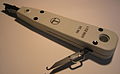
As previously mentioned the actual connections are made using Insulation-displacement connectors (IDC). A punch down tool is required to do this and two sorts are available. One is of plastic construction and only intended for occasional use. The other is a professional tool used by installers, which is a spring loaded push down tool that both inserts the wire and trims it in one action: an example is shown in the photograph. It also comes with a tool for removing wires from sockets. From Q3 2016, Openreach started using a new, "toolless" version of the demarcation socket—the NTE5C—which does not require an IDC tool to make the connections.
Krone IDC Tool, showing the wire removal tool open officially known as Inserter Wire No. 2a
Plastic IDC Tool, for occasional use only
4 wire cable the old sort, but much thinner
6 wire cable the current type
LJ 2/1A - 4 wire cable connected to a master socket
LJ 2/1A - 6 wire cable connected to a master socket
Cabling arrangements
Shown below are the cabling arrangements for both 4-wire and 6-wire cable. Initially 4-wire was used and many older installations still use it, then the 6-wire became the new standard, but the 4-wire has latterly been reissued to all Openreach technicians as part of cost savings. Modern 4-wire however is the same diameter as 6-wire to allow technicians to retain existing tacking guns and cable clips. Note that the wires in the 6-wire cable are coloured with two colours in a ratio of four to one in length, with the first colour mentioned being the predominant one, e.g. if the indicated colour of the wire is W-B then the wire will be coloured white for 12mm, then blue for 3mm and so on. (In other words, it looks like a white wire with blue patches on it.)
Four wire cabling
Six wire cabling
Strictly speaking, a textbook installation will only actually use pins 2, 5 (for the voice) and 3 (for the ringer). Having said this, most modern telephones no longer require a ringing capacitor may have 2-wire connections, which means that extension wiring can usually be run with only pins 2 and 5. Often where multi-core cable is used, the remaining cables are used for wiring extensions on additional incoming telephone lines.
DSL FilterReplacement face plate for an NTE5 containing a built-in ADSL filter
In order to use broadbandInternet services simultaneously with voice telephony, it is necessary to use a DSL filter. This is a low pass filter in line with the phone outlet. This prevents high frequency data noise from affecting the lower frequency voice bandwidth and it also prevents the low impedance of the connected phone from attenuating or modulating the high speed DSL data Path. Enough bandwidth is retained for voice telephony and the majority is used for high speed data.
All phones (or other voice band devices) must be connected via a filter (either a separate filter for each phone or one filter covering multiple phones) to avoid interference between the phones and the DSL signal. If the data transmission is still audible the use of two DSL filters, daisychained in series, should eliminate the problem. The RJ11 female port provided on the filter case simply connects the DSL router directly to the phone line (most DSL filters have a socket marked DSL or ADSL that just connects the DSL line pair directly through to the incoming phone line pair via the BT plug, without any filtering or processing of any kind). The ringer wire is unnecessary in unfiltered parts of the wiring and its removal can often improve performance and reliability of the broadband service. This is due to the unbalancing effect that the ringer wire (on long extensions) can have on the matched twisted pair. Thus reducing the signal to noise ratio and also the high frequency response of the subscriber line.
When ADSL was first introduced in the UK it was installed by a technician who replaced the front part of the NTE5 (if the property still had an old style master socket it would be replaced with an NTE5) with one containing a filter. Any hardwired phone extensions were disconnected from the original front part and connected to filtered terminals on the back of the filter. The DSL modem (which at the time was also BT supplied) and, if present, a phone or plug-in extension, could then be plugged into the front. If it was desired to locate the DSL modem away from the master socket a plug-in ADSL extension kit could be purchased.
BT also offered "wires-only" ADSL service and promoted the technique of using a separate plug-in filter on every socket.[13] While both technically inferior and far less tidy than the solution BT engineers had used, it was usually adequate and was simple enough for a non-technical householder to understand. The more discerning customer can purchase a variety of hardwired filtering products, including replacement front plates for the NTE5, some of which have unfiltered as well as filtered terminals on the back to avoid the need to plug in the extension wiring that leads to the DSL modem.
NTE5 showing it being fitted with a BT IPlate. The IPlate is the part in the middle of the sandwich
In 2008 BT trialled and launched their 'IPlate'; the "I" is for interstitial, as it is fitted between the socket and the front panel. This plate is fitted by the consumer inside the NTE 5 and reduces interference carried by the 3rd (bell) wire. The reduced interference allows faster broadband speeds - BT claim a speed improvement of up to 1.5Mbit/s with a theoretical 4Mbit/s. By November 2009 BT were calling the I-plate a "BT Broadband Accelerator".
Structured cabling
Structured cabling systems are general-purpose communications wires installed in offices and increasingly also homes, which can be used for several different communication technologies (analog phone, ADSL, ISDN, Ethernet, video, etc.). The most common type uses Category 5 cables (four twisted pairs with 100 ohm impedance) between 8P8C (colloquially and incorrectly called RJ45) room sockets and a central patch panel.
The A and B wires of an analogue phone line appear in a structured cabling system usually on the centre pins of the 8P8C connector (pins 4 and 5; the blue/white TIA/EIA-568 pair 1 in Cat5 cables). In most other countries, those two wires are all that is needed to connect an analogue telephone. In the UK, however, many telephone circuits still have an anti-tinkle connection between the master socket and extensions on a third wire. But such a 3-wire interface is not the symmetric interface needed for balanced twisted-pair transmission lines, and therefore prone to electromagnetic interference and crosstalk with nearby other wiring. It is modern practice to remove the bell wire to rebalance the circuit and thus reduce potential interference from office or far field RF interference. The telephone is plugged at the other end into the structured cabling via a line adapter unit (LAU) / Mod-Tap / Molex that contains the capacitor needed to connect the bell signal. Different types of LAUs are on the market:
PSTN secondary/slave: for phones that need no bell wire
PABX master: contains ring capacitor, to provide from the 8P8C 2-wire interface the 3rd bell wire required by UK phones
PSTN master: implements all the circuitry found in a BT master socket, including surge protection, ring capacitor, test resistor
There exists no well-established standard in which polarity pins 2 and 5 of the phone socket are connected to pins 4 and 5 of the 8P8C connector; both alternatives are common.[14] This polarity is not normally important; BT does specify that the B wire is more negative than the A, though they no longer specify which of the A and B wires are connected to pins 2 and 5 of their master telephone socket,[5] although earlier standards specified that the A wire be connected to 5 and the B wire to 2.
↑ BS 6312-1:1994. Connectors for analogue telecommunication interfaces. Specification for plugs.
↑ BS 6312-2.1:1994. Connectors for analogue telecommunication interfaces. Sockets for use with plugs specified in BS 6312:Part 1. Specification for sockets. General requirements.
↑ BS 6312-2.2:1997. Connectors for analogue telecommunication interfaces. Sockets for use with plugs specified in BS 6312-1. Particular requirements for fixed socket-outlets used in permanent wiring installations.
↑ BS 6305:1992. Specification for general requirements for apparatus for connection to public switched telephone networks run by certain public telecommunication operators. (obsolescent)
In telecommunications, an acoustic coupler is an interface device for coupling electrical signals by acoustical means—usually into and out of a telephone.
Digital subscriber line is a family of technologies that are used to transmit digital data over telephone lines. In telecommunications marketing, the term DSL is widely understood to mean asymmetric digital subscriber line (ADSL), the most commonly installed DSL technology, for Internet access.
A 600 series connector is an obsolete three-pin connector with up to six conductors.
Components of an electrical circuit are electrically connected if an electric current can run between them through an electrical conductor. An electrical connector is an electromechanical device used to create an electrical connection between parts of an electrical circuit, or between different electrical circuits, thereby joining them into a larger circuit.
A digital subscriber line access multiplexer is a network device, often located in telephone exchanges, that connects multiple customer digital subscriber line (DSL) interfaces to a high-speed digital communications channel using multiplexing techniques. Its cable internet (DOCSIS) counterpart is the cable modem termination system.
In telephony, the demarcation point is the point at which the public switched telephone network ends and connects with the customer's on-premises wiring. It is the dividing line which determines who is responsible for installation and maintenance of wiring and equipment—customer/subscriber, or telephone company/provider. The demarcation point varies between countries and has changed over time.
A registered jack (RJ) is a standardized telecommunication network interface for connecting voice and data equipment to a computer service provided by a local exchange carrier or long distance carrier. Registered interfaces were first defined in the Universal Service Ordering Code (USOC) system of the Bell System in the United States for complying with the registration program for customer-supplied telephone equipment mandated by the Federal Communications Commission (FCC) in the 1970s. They were subsequently codified in title 47 of the Code of Federal Regulations Part 68. Registered jack connections began to see use after their invention in 1973 by Bell Labs. The specification includes physical construction, wiring, and signal semantics. Accordingly, registered jacks are primarily named by the letters RJ, followed by two digits that express the type. Additional letter suffixes indicate minor variations. For example, RJ11, RJ14, and RJ25 are the most commonly used interfaces for telephone connections for one-, two-, and three-line service, respectively. Although these standards are legal definitions in the United States, some interfaces are used worldwide.
A telephone jack and a telephone plug are electrical connectors for connecting a telephone set or other telecommunications apparatus to the telephone wiring inside a building, establishing a connection to a telephone network. The plug is inserted into its counterpart, the jack, which is commonly affixed to a wall or baseboard. The standards for telephone jacks and plugs vary from country to country, though the 6P2C style modular plug has become by far the most common type.
A telephone line or telephone circuit is a single-user circuit on a telephone communication system. It is designed to reproduce speech of a quality that is understandable. It is the physical wire or other signaling medium connecting the user's telephone apparatus to the telecommunications network, and usually also implies a single telephone number for billing purposes reserved for that user. Telephone lines are used to deliver landline telephone service and digital subscriber line (DSL) phone cable service to the premises. Telephone overhead lines are connected to the public switched telephone network. The voltage at a subscriber's network interface is typically 48 V between the ring and tip wires, with tip near ground and ring at –48 V.
A standard Swedish telephone plug carries one telephone line and has four flat metal pins and one plastic pin. The design is only used by Televerket in Sweden and older Póstur og Sími installations in Iceland. Neither plug nor socket is compatible with other plugs and sockets. It is defined in Swedish Standard SS 455 15 50.
The Freebox is an ADSL-VDSL-FTTH modem and a set-top box that the French Internet service provider named Free provides to its DSL-FTTH subscribers.
In telecommunications, structured cabling is building or campus cabling infrastructure that consists of a number of standardized smaller elements called subsystems. Structured cabling components include twisted pair and optical cabling, patch panels and patch cables.
As a former British colony and territory, technical standards in Hong Kong of today has been largely influenced by that of the United Kingdom, with some exceptions due to local and practical considerations.
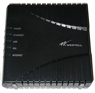
A digital subscriber line (DSL) modem is a device used to connect a computer or router to a telephone line which provides the digital subscriber line (DSL) service for connection to the Internet, which is often called DSL broadband. The modem connects to a single computer or router, through an Ethernet port, USB port, or is installed in a computer PCI slot.
A DSL filter is an analog low-pass filter installed between analog devices and a plain old telephone service (POTS) line. The DSL filter prevents interference between such devices and a digital subscriber line (DSL) service connected to the same line. Without DSL filters, signals or echoes from analog devices at the top of their frequency range can reduce performance and create connection problems with DSL service, while those from the DSL service at the bottom of its range can cause line noise and other problems for analog devices.
A modular connector is a type of electrical connector for cords and cables of electronic devices and appliances, such as in computer networking, telecommunication equipment, and audio headsets.
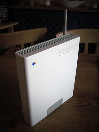
The BT Smart Hub is a family of wireless residential gateway router modems distributed by BT for use with their own products and services and those of wholesale resellers but not with other Internet services. Since v 5 Home/Smart Hubs support the faster Wi-Fi 802.11ac standard, in addition to the 802.11b/g/n standards. All models of the Home Hub prior to Home Hub 3 support VoIP Internet telephony via BT's Broadband Talk service, and are compatible with DECT telephone handsets. Since the Home Hub 4, all models have been dual band.
BT Highway was a UK retail ISDN2e service from British Telecom which was announced in November 1997 and withdrawn in February 2007. In the domestic market, it was sold as BT Home Highway and for small businesses, BT Business Highway. These names were used simply to differentiate billing schemes; the hardware for both services used the name BT Highway. Unlike regular ISDN2e service where only a digital S interface is provided BT Highway provided both digital and analogue connections simplifying migration from regular POTS service.
Asymmetric digital subscriber line (ADSL) is a type of digital subscriber line (DSL) technology, a data communications technology that enables faster data transmission over copper telephone lines than a conventional voiceband modem can provide. ADSL differs from the less common symmetric digital subscriber line (SDSL). In ADSL, bandwidth and bit rate are said to be asymmetric, meaning greater toward the customer premises (downstream) than the reverse (upstream). Providers usually market ADSL as an Internet access service primarily for downloading content from the Internet, but not for serving content accessed by others.
The Danish telephone plug is the special flat round telephone plug used in Denmark for POTS (analog) telephone lines and some "raw copper" telephone lines. The plug has 3 flat pins arranged at right angles to each other. This plug is used in few if any other places in the world, and most equipment now made uses the US/International RJ11 socket on the device end and includes either a cable with the Danish Telephone Plug at the wall end, or a standard RJ11 to RJ11 cable with a bundled Telephone Adapter.
This page is based on this Wikipedia article Text is available under the CC BY-SA 4.0 license; additional terms may apply. Images, videos and audio are available under their respective licenses.