Image stitching

Last updated
Two images stitched together. The photo on the right is distorted slightly so that it matches up with the one on the left. Riola1.jpg
Two images stitched together. The photo on the right is distorted slightly so that it matches up with the one on the left.

Image stitching or photo stitching is the process of combining multiple photographic images with overlapping fields of view to produce a segmented panorama or high-resolution image. Commonly performed through the use of computer software, most approaches to image stitching require nearly exact overlaps between images and identical exposures to produce seamless results, [1] [2] although some stitching algorithms actually benefit from differently exposed images by doing high-dynamic-range imaging in regions of overlap. [3] [4] Some digital cameras can stitch their photos internally.

Contents

Applications

Image stitching is widely used in modern applications, such as the following:

Alcatraz03182006.jpg
Alcatraz Island, shown in a panorama created by image stitching

Process

The image stitching process can be divided into three main components: image registration, calibration, and blending.

Image stitching algorithms

This sample image shows geometrical registration and stitching lines in panorama creation. Rochester NY.jpg
This sample image shows geometrical registration and stitching lines in panorama creation.

In order to estimate image alignment, algorithms are needed to determine the appropriate mathematical model relating pixel coordinates in one image to pixel coordinates in another. Algorithms that combine direct pixel-to-pixel comparisons with gradient descent (and other optimization techniques) can be used to estimate these parameters.

Distinctive features can be found in each image and then efficiently matched to rapidly establish correspondences between pairs of images. When multiple images exist in a panorama, techniques have been developed to compute a globally consistent set of alignments and to efficiently discover which images overlap one another.

A final compositing surface onto which to warp or projectively transform and place all of the aligned images is needed, as are algorithms to seamlessly blend the overlapping images, even in the presence of parallax, lens distortion, scene motion, and exposure differences.

Image stitching issues

Since the illumination in two views cannot be guaranteed to be identical, stitching two images could create a visible seam. Other reasons for seams could be the background changing between two images for the same continuous foreground. Other major issues to deal with are the presence of parallax, lens distortion, scene motion, and exposure differences. In a non-ideal real-life case, the intensity varies across the whole scene, and so does the contrast and intensity across frames. Additionally, the aspect ratio of a panorama image needs to be taken into account to create a visually pleasing composite.

For panoramic stitching, the ideal set of images will have a reasonable amount of overlap (at least 15–30%) to overcome lens distortion and have enough detectable features. The set of images will have consistent exposure between frames to minimize the probability of seams occurring.

Keypoint detection

Feature detection is necessary to automatically find correspondences between images. Robust correspondences are required in order to estimate the necessary transformation to align an image with the image it is being composited on. Corners, blobs, Harris corners, and differences of Gaussians of Harris corners are good features since they are repeatable and distinct.

One of the first operators for interest point detection was developed by Hans P. Moravec in 1977 for his research involving the automatic navigation of a robot through a clustered environment. Moravec also defined the concept of "points of interest" in an image and concluded these interest points could be used to find matching regions in different images. The Moravec operator is considered to be a corner detector because it defines interest points as points where there are large intensity variations in all directions. This often is the case at corners. However, Moravec was not specifically interested in finding corners, just distinct regions in an image that could be used to register consecutive image frames.

Harris and Stephens improved upon Moravec's corner detector by considering the differential of the corner score with respect to direction directly. They needed it as a processing step to build interpretations of a robot's environment based on image sequences. Like Moravec, they needed a method to match corresponding points in consecutive image frames, but were interested in tracking both corners and edges between frames.

SIFT and SURF are recent key-point or interest point detector algorithms but a point to note is that SURF is patented and its commercial usage restricted. Once a feature has been detected, a descriptor method like SIFT descriptor can be applied to later match them.

Registration

Image registration involves matching features [7] in a set of images or using direct alignment methods to search for image alignments that minimize the sum of absolute differences between overlapping pixels. [8] When using direct alignment methods one might first calibrate one's images to get better results. Additionally, users may input a rough model of the panorama to help the feature matching stage, so that e.g. only neighboring images are searched for matching features. Since there are smaller group of features for matching, the result of the search is more accurate and execution of the comparison is faster.

To estimate a robust model from the data, a common method used is known as RANSAC. The name RANSAC is an abbreviation for "RANdom SAmple Consensus". It is an iterative method for robust parameter estimation to fit mathematical models from sets of observed data points which may contain outliers. The algorithm is non-deterministic in the sense that it produces a reasonable result only with a certain probability, with this probability increasing as more iterations are performed. It being a probabilistic method means that different results will be obtained for every time the algorithm is run.

The RANSAC algorithm has found many applications in computer vision, including the simultaneous solving of the correspondence problem and the estimation of the fundamental matrix related to a pair of stereo cameras. The basic assumption of the method is that the data consists of "inliers", i.e., data whose distribution can be explained by some mathematical model, and "outliers" which are data that do not fit the model. Outliers are considered points which come from noise, erroneous measurements, or simply incorrect data.

For the problem of homography estimation, RANSAC works by trying to fit several models using some of the point pairs and then checking if the models were able to relate most of the points. The best model – the homography, which produces the highest number of correct matches – is then chosen as the answer for the problem; thus, if the ratio of number of outliers to data points is very low, the RANSAC outputs a decent model fitting the data.

Calibration

Image calibration aims to minimize differences between an ideal lens models and the camera-lens combination that was used, optical defects such as distortions, exposure differences between images, vignetting, [9] camera response and chromatic aberrations. If feature detection methods were used to register images and absolute positions of the features were recorded and saved, stitching software may use the data for geometric optimization of the images in addition to placing the images on the panosphere. Panotools and its various derivative programs use this method.

Alignment

Alignment may be necessary to transform an image to match the view point of the image it is being composited with. Alignment, in simple terms, is a change in the coordinates system so that it adopts a new coordinate system which outputs image matching the required viewpoint. The types of transformations an image may go through are pure translation, pure rotation, a similarity transform which includes translation, rotation and scaling of the image which needs to be transformed, Affine or projective transform.

Projective transformation is the farthest an image can transform (in the set of two dimensional planar transformations), where only visible features that are preserved in the transformed image are straight lines whereas parallelism is maintained in an affine transform.

Projective transformation can be mathematically described as

x’ = H x,

where x is points in the old coordinate system, x’ is the corresponding points in the transformed image and H is the homography matrix.

Expressing the points x and x’ using the camera intrinsics (K and K’) and its rotation and translation [R t] to the real-world coordinates X and X’, we get

x = K [R t] X and x’ = K’ [R’ t’] X’.

Using the above two equations and the homography relation between x’ and x, we can derive

H = K’ R’ R−1 K−1

The homography matrix H has 8 parameters or degrees of freedom. The homography can be computed using Direct Linear Transform and Singular value decomposition with

A h = 0,

where A is the matrix constructed using the coordinates of correspondences and h is the one dimensional vector of the 9 elements of the reshaped homography matrix. To get to h we can simple apply SVD: A = U S V T And h = V (column corresponding to the smallest singular vector). This is true since h lies in the null space of A. Since we have 8 degrees of freedom the algorithm requires at least four point correspondences. In case when RANSAC is used to estimate the homography and multiple correspondences are available the correct homography matrix is the one with the maximum number of inliers.

Compositing

Compositing is the process where the rectified images are aligned in such a way that they appear as a single shot of a scene. Compositing can be automatically done since the algorithm now knows which correspondences overlap.

Blending

Image blending involves executing the adjustments figured out in the calibration stage, combined with remapping of the images to an output projection. Colors are adjusted between images to compensate for exposure differences. If applicable, high dynamic range merging is done along with motion compensation and deghosting. Images are blended together and seam line adjustment is done to minimize the visibility of seams between images.

The seam can be reduced by a simple gain adjustment. This compensation is basically minimizing intensity difference of overlapping pixels. Image blending algorithm allots more weight to pixels near the center of the image. Gain compensated and multi band blended images compare the best. IJCV 2007.

Straightening is another method to rectify the image. Matthew Brown and David G. Lowe in their paper ‘Automatic Panoramic Image Stitching using Invariant Features’ describe methods of straightening which apply a global rotation such that vector u is vertical (in the rendering frame) which effectively removes the wavy effect from output panoramas. This process is similar to image rectification, and more generally software correction of optical distortions in single photographs.

Even after gain compensation, some image edges are still visible due to a number of unmodelled effects, such as vignetting (intensity decreases towards the edge of the image), parallax effects due to unwanted motion of the optical centre, mis-registration errors due to mismodelling of the camera, radial distortion and so on. Due to these reasons they propose a blending strategy called multi band blending.

Projective layouts

Comparison of Mercator and rectilinear projections
Comparing distortions near poles of panosphere by various cylindrical formats. Comparison of various cylindrical panoramic formats 165 degrees vertical field of view and 360 degrees horizontal field of view.jpg
Comparing distortions near poles of panosphere by various cylindrical formats.

For image segments that have been taken from the same point in space, stitched images can be arranged using one of various map projections.

Rectilinear

Rectilinear projection , where the stitched image is viewed on a two-dimensional plane intersecting the panosphere in a single point. Lines that are straight in reality are shown as straight regardless of their directions on the image. Wide views - around 120° or so - start to exhibit severe distortion near the image borders. One case of rectilinear projection is the use of cube faces with cubic mapping for panorama viewing. Panorama is mapped to six squares, each cube face showing 90 by 90 degree area of the panorama.

Cylindrical

Cylindrical projection , where the stitched image shows a 360° horizontal field of view and a limited vertical field of view. Panoramas in this projection are meant to be viewed as though the image is wrapped into a cylinder and viewed from within. When viewed on a 2D plane, horizontal lines appear curved while vertical lines remain straight. [10] Vertical distortion increases rapidly when nearing the top of the panosphere. There are various other cylindrical formats, such as Mercator and Miller cylindrical which have less distortion near the poles of the panosphere.

Spherical

2D plane of a 360deg sphere panorama
(view as a 360deg interactive panorama) Eckersdorf OT Hardt 360 pano.jpg
2D plane of a 360° sphere panorama
( view as a 360° interactive panorama )

Spherical projection or equirectangular projection — which is strictly speaking another cylindrical projection — where the stitched image shows a 360° horizontal by 180° vertical field of view i.e. the whole sphere. Panoramas in this projection are meant to be viewed as though the image is wrapped into a sphere and viewed from within. When viewed on a 2D plane, horizontal lines appear curved as in a cylindrical projection, while vertical lines remain vertical. [10]

Panini

Since a panorama is basically a map of a sphere, various other mapping projections from cartographers can also be used if so desired. Additionally there are specialized projections which may have more aesthetically pleasing advantages over normal cartography projections such as Hugin's Panini projection [11] - named after Italian vedutismo painter Giovanni Paolo Panini [12] - or PTgui's Vedutismo projection. [13] Different projections may be combined in same image for fine tuning the final look of the output image. [14]

Stereographic

Stereographic projection or fisheye projection can be used to form a little planet panorama by pointing the virtual camera straight down and setting the field of view large enough to show the whole ground and some of the areas above it; pointing the virtual camera upwards creates a tunnel effect. Conformality of the stereographic projection may produce more visually pleasing result than equal area fisheye projection as discussed in the stereo-graphic projection's article.

Artifacts

London Aquatics Centre interior.jpg
Artifacts due to parallax error
London Aquatics Centre interior.jpg
Artifacts due to subject movement

The use of images not taken from the same place (on a pivot about the entrance pupil of the camera) [15] can lead to parallax errors in the final product. When the captured scene features rapid movement or dynamic motion, artifacts may occur as a result of time differences between the image segments. "Blind stitching" through feature-based alignment methods (see autostitch), as opposed to manual selection and stitching, can cause imperfections in the assembly of the panorama.

Software

Dedicated programs include Autostitch, Hugin, Ptgui, Panorama Tools, Microsoft Research Image Composite Editor and CleVR Stitcher. Many other programs can also stitch multiple images; a popular example is Adobe Systems' Photoshop, which includes a tool known as Photomerge and, in the latest versions, the new Auto-Blend. Other programs such as VideoStitch make it possible to stitch videos, and Vahana VR enables real-time video stitching. Image Stitching module for QuickPHOTO microscope software enables to interactively stitch together multiple fields of view from microscope using camera's live view. It can be also used for manual stitching of whole microscopy samples.

See also

Related Research Articles

<span class="mw-page-title-main">Texture mapping</span> Method of defining surface detail on a computer-generated graphic or 3D model

Texture mapping is a method for mapping a texture on a computer-generated graphic. Texture here can be high frequency detail, surface texture, or color.

<span class="mw-page-title-main">Z-buffering</span> Type of data buffer in computer graphics

A depth buffer, also known as a z-buffer, is a type of data buffer used in computer graphics to represent depth information of objects in 3D space from a particular perspective. The depth is stored as a height map of the scene, the values representing a distance to camera, with 0 being the closest. The encoding scheme may be flipped with the highest number being the value closest to camera. Depth buffers are an aid to rendering a scene to ensure that the correct polygons properly occlude other polygons. Z-buffering was first described in 1974 by Wolfgang Straßer in his PhD thesis on fast algorithms for rendering occluded objects. A similar solution to determining overlapping polygons is the painter's algorithm, which is capable of handling non-opaque scene elements, though at the cost of efficiency and incorrect results.

<span class="mw-page-title-main">Ray casting</span> Methodological basis for 3D CAD/CAM solid modeling and image rendering

Ray casting is the methodological basis for 3D CAD/CAM solid modeling and image rendering. It is essentially the same as ray tracing for computer graphics where virtual light rays are "cast" or "traced" on their path from the focal point of a camera through each pixel in the camera sensor to determine what is visible along the ray in the 3D scene. The term "Ray Casting" was introduced by Scott Roth while at the General Motors Research Labs from 1978–1980. His paper, "Ray Casting for Modeling Solids", describes modeled solid objects by combining primitive solids, such as blocks and cylinders, using the set operators union (+), intersection (&), and difference (-). The general idea of using these binary operators for solid modeling is largely due to Voelcker and Requicha's geometric modelling group at the University of Rochester. See solid modeling for a broad overview of solid modeling methods. This figure on the right shows a U-Joint modeled from cylinders and blocks in a binary tree using Roth's ray casting system in 1979.

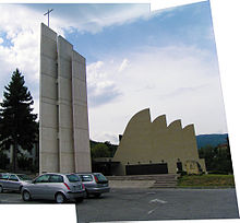
The scale-invariant feature transform (SIFT) is a computer vision algorithm to detect, describe, and match local features in images, invented by David Lowe in 1999. Applications include object recognition, robotic mapping and navigation, image stitching, 3D modeling, gesture recognition, video tracking, individual identification of wildlife and match moving.

<span class="mw-page-title-main">Hugin (software)</span> Photo stitching software

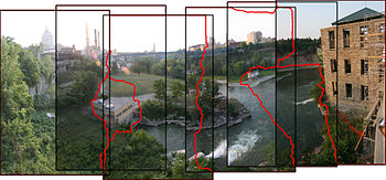
Hugin is a cross-platform open source panorama photo stitching and HDR merging program developed by Pablo d'Angelo and others. It is a GUI front-end for Helmut Dersch's Panorama Tools and Andrew Mihal's Enblend and Enfuse. Stitching is accomplished by using several overlapping photos taken from the same location, and using control points to align and transform the photos so that they can be blended together to form a larger image. Hugin allows for the easy creation of control points between two images, optimization of the image transforms along with a preview window so the user can see whether the panorama is acceptable. Once the preview is correct, the panorama can be fully stitched, transformed and saved in a standard image format.

<span class="mw-page-title-main">Motion estimation</span> Process used in video coding/compression

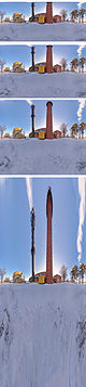
In computer vision and image processing, motion estimation is the process of determining motion vectors that describe the transformation from one 2D image to another; usually from adjacent frames in a video sequence. It is an ill-posed problem as the motion happens in three dimensions (3D) but the images are a projection of the 3D scene onto a 2D plane. The motion vectors may relate to the whole image or specific parts, such as rectangular blocks, arbitrary shaped patches or even per pixel. The motion vectors may be represented by a translational model or many other models that can approximate the motion of a real video camera, such as rotation and translation in all three dimensions and zoom.

In geometric optics, distortion is a deviation from rectilinear projection; a projection in which straight lines in a scene remain straight in an image. It is a form of optical aberration.

Optical resolution describes the ability of an imaging system to resolve detail, in the object that is being imaged. An imaging system may have many individual components, including one or more lenses, and/or recording and display components. Each of these contributes to the optical resolution of the system; the environment in which the imaging is done often is a further important factor.

In the fields of computing and computer vision, pose represents the position and orientation of an object, usually in three dimensions. Poses are often stored internally as transformation matrices. The term “pose” is largely synonymous with the term “transform”, but a transform may often include scale, whereas pose does not.

Camera resectioning is the process of estimating the parameters of a pinhole camera model approximating the camera that produced a given photograph or video; it determines which incoming light ray is associated with each pixel on the resulting image. Basically, the process determines the pose of the pinhole camera.

The correspondence problem refers to the problem of ascertaining which parts of one image correspond to which parts of another image, where differences are due to movement of the camera, the elapse of time, and/or movement of objects in the photos.

Binocular disparity refers to the difference in image location of an object seen by the left and right eyes, resulting from the eyes’ horizontal separation (parallax). The mind uses binocular disparity to extract depth information from the two-dimensional retinal images in stereopsis. In computer vision, binocular disparity refers to the difference in coordinates of similar features within two stereo images.

<span class="mw-page-title-main">Image rectification</span>

Image rectification is a transformation process used to project images onto a common image plane. This process has several degrees of freedom and there are many strategies for transforming images to the common plane. Image rectification is used in computer stereo vision to simplify the problem of finding matching points between images, and in geographic information systems to merge images taken from multiple perspectives into a common map coordinate system.

In computer vision, triangulation refers to the process of determining a point in 3D space given its projections onto two, or more, images. In order to solve this problem it is necessary to know the parameters of the camera projection function from 3D to 2D for the cameras involved, in the simplest case represented by the camera matrices. Triangulation is sometimes also referred to as reconstruction or intersection.

<span class="mw-page-title-main">Bundle adjustment</span>

In photogrammetry and computer stereo vision, bundle adjustment is simultaneous refining of the 3D coordinates describing the scene geometry, the parameters of the relative motion, and the optical characteristics of the camera(s) employed to acquire the images, given a set of images depicting a number of 3D points from different viewpoints. Its name refers to the geometrical bundles of light rays originating from each 3D feature and converging on each camera's optical center, which are adjusted optimally according to an optimality criterion involving the corresponding image projections of all points.

<span class="mw-page-title-main">Image Composite Editor</span>

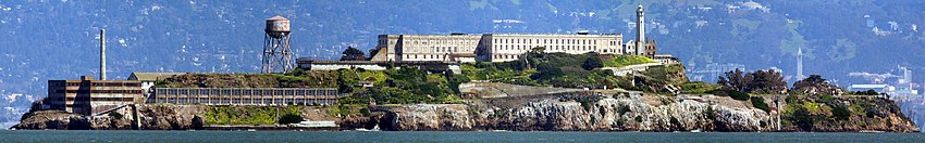
Image Composite Editor is an advanced panoramic image stitcher made by the Microsoft Research division of Microsoft Corporation.

Camera auto-calibration is the process of determining internal camera parameters directly from multiple uncalibrated images of unstructured scenes. In contrast to classic camera calibration, auto-calibration does not require any special calibration objects in the scene. In the visual effects industry, camera auto-calibration is often part of the "Match Moving" process where a synthetic camera trajectory and intrinsic projection model are solved to reproject synthetic content into video.

<span class="mw-page-title-main">3D reconstruction from multiple images</span> Creation of a 3D model from a set of images

3D reconstruction from multiple images is the creation of three-dimensional models from a set of images. It is the reverse process of obtaining 2D images from 3D scenes.

<span class="mw-page-title-main">Homography (computer vision)</span> Relation of two images with software

In the field of computer vision, any two images of the same planar surface in space are related by a homography. This has many practical applications, such as image rectification, image registration, or camera motion—rotation and translation—between two images. Once camera resectioning has been done from an estimated homography matrix, this information may be used for navigation, or to insert models of 3D objects into an image or video, so that they are rendered with the correct perspective and appear to have been part of the original scene.

In computer vision, rigid motion segmentation is the process of separating regions, features, or trajectories from a video sequence into coherent subsets of space and time. These subsets correspond to independent rigidly moving objects in the scene. The goal of this segmentation is to differentiate and extract the meaningful rigid motion from the background and analyze it. Image segmentation techniques labels the pixels to be a part of pixels with certain characteristics at a particular time. Here, the pixels are segmented depending on its relative movement over a period of time i.e. the time of the video sequence.

References

  1. Mann, Steve; Picard, R. W. (November 13–16, 1994). "Virtual bellows: constructing high-quality stills from video". Proceedings of the IEEE First International Conference on Image Processing. IEEE International Conference. Austin, Texas: IEEE. doi:10.1109/ICIP.1994.413336. S2CID   16153752.
  2. Ward, Greg (2006). "Hiding seams in high dynamic range panoramas". Proceedings of the 3rd Symposium on Applied Perception in Graphics and Visualization. ACM International Conference. Vol. 153. ACM. doi:10.1145/1140491.1140527. ISBN   1-59593-429-4.
  3. Steve Mann. "Compositing Multiple Pictures of the Same Scene", Proceedings of the 46th Annual Imaging Science & Technology Conference, May 9–14, Cambridge, Massachusetts, 1993
  4. S. Mann, C. Manders, and J. Fung, "The Lightspace Change Constraint Equation (LCCE) with practical application to estimation of the projectivity+gain transformation between multiple pictures of the same subject matter Archived 2023-03-14 at the Wayback Machine " IEEE International Conference on Acoustics, Speech, and Signal Processing, 6–10 April 2003, pp III - 481-4 vol.3
  5. Hannuksela, Jari; Sangi, Pekka; Heikkila, Janne; Liu, Xu; Doermann, David (2007). "Document Image Mosaicing with Mobile Phones". 14th International Conference on Image Analysis and Processing (ICIAP 2007). pp. 575–582. doi:10.1109/ICIAP.2007.4362839. ISBN   978-0-7695-2877-9.
  6. Breszcz, M.; Breckon, T. P. (August 2015). "Real-time Construction and Visualization of Drift-Free Video Mosaics from Unconstrained Camera Motion" (PDF). The Journal of Engineering. 2015 (16): 229–240. doi: 10.1049/joe.2015.0016 . breszcz15mosaic.
  7. Szeliski, Richard (2005). "Image Alignment and Stitching" (PDF). Retrieved 2008-06-01.{{cite journal}}: Cite journal requires |journal= (help)
  8. S. Suen; E. Lam; K. Wong (2007). "Photographic stitching with optimized object and color matching based on image derivatives". Optics Express . 15 (12): 7689–7696. Bibcode:2007OExpr..15.7689S. doi: 10.1364/OE.15.007689 . PMID   19547097.
  9. d'Angelo, Pablo (2007). "Radiometric alignment and vignetting calibration" (PDF).
  10. 1 2 Wells, Sarah; et al. (2007). "IATH Best Practices Guide to Digital Panoramic Photography" . Retrieved 2008-06-01.{{cite journal}}: Cite journal requires |journal= (help)
  11. Hugin.sourceforge.net, hugin manual: Panini
  12. Groups.google.com, hugin-ptx mailing list, December 29, 2008
  13. PTgui: Projections
  14. Tawbaware.com, PTAssembler projections: Hybrid
  15. Littlefield, Rik (2006-02-06). "Theory of the "No-Parallax" Point in Panorama Photography" (PDF). ver. 1.0. Retrieved 2008-06-01.{{cite journal}}: Cite journal requires |journal= (help)