Loading coil

Last updated

Pupin coils in PTT Museum in Belgrade (Serbia) Pupin coils in PTT Museum in Belgrade 04.jpg
Pupin coils in PTT Museum in Belgrade (Serbia)

A loading coil or load coil is an inductor that is inserted into an electronic circuit to increase its inductance. The term originated in the 19th century for inductors used to prevent signal distortion in long-distance telegraph transmission cables. The term is also used for inductors in radio antennas, or between the antenna and its feedline, to make an electrically short antenna resonant at its operating frequency.

Contents

The concept of loading coils was discovered by Oliver Heaviside in studying the problem of slow signalling speed of the first transatlantic telegraph cable in the 1860s. He concluded additional inductance was required to prevent amplitude and time delay distortion of the transmitted signal. The mathematical condition for distortion-free transmission is known as the Heaviside condition. Previous telegraph lines were overland or shorter and hence had less delay, and the need for extra inductance was not as great. Submarine communications cables are particularly subject to the problem, but early 20th century installations using balanced pairs were often continuously loaded with iron wire or tape rather than discretely with loading coils, which avoided the sealing problem.

Loading coils are historically also known as Pupin coils after Mihajlo Pupin, especially when used for the Heaviside condition and the process of inserting them is sometimes called pupinization.

Applications

Schematic of a balanced loaded telephone line. The capacitors are not discrete components but represent the distributed capacitance between the closely spaced wire conductors of the line, this is indicated by the dotted lines. The loading coils prevent the audio (voice) signal from being distorted by the line capacitance. The windings of the loading coil are wound such that the magnetic flux induced in the core is in the same direction for both windings. Loaded line schematic.svg
Schematic of a balanced loaded telephone line. The capacitors are not discrete components but represent the distributed capacitance between the closely spaced wire conductors of the line, this is indicated by the dotted lines. The loading coils prevent the audio (voice) signal from being distorted by the line capacitance. The windings of the loading coil are wound such that the magnetic flux induced in the core is in the same direction for both windings.

Telephone lines

Toroidal telephone loading coil.jpg
Telephone loading coils 1922.jpg
(left) Toroidal 0.175 H loading coil for an AT&T long distance telephone trunkline from New York to Chicago 1922. Each of the 108 twisted pairs in the cable required a coil. The coils were enclosed in an oil-filled steel tank (right) on the telephone pole. The cable required loading coils every 6000 ft (1.83 km).

A common application of loading coils is to improve the voice-frequency amplitude response characteristics of the twisted balanced pairs in a telephone cable. Because twisted pair is a balanced format, half the loading coil must be inserted in each leg of the pair to maintain the balance. It is common for both these windings to be formed on the same core. This increases the flux linkages, without which the number of turns on the coil would need to be increased. Despite the use of common cores, such loading coils do not comprise transformers, as they do not provide coupling to other circuits.

Loading coils inserted periodically in series with a pair of wires reduce the attenuation at the higher voice frequencies up to the cutoff frequency of the low-pass filter formed by the inductance of the coils (plus the distributed inductance of the wires) and the distributed capacitance between the wires. Above the cutoff frequency, attenuation increases rapidly. The shorter the distance between the coils, the higher the cut-off frequency. The cutoff effect is an artifact of using lumped inductors. With loading methods using continuous distributed inductance there is no cutoff.

Without loading coils, the line response is dominated by the resistance and capacitance of the line with the attenuation gently increasing with frequency. With loading coils of exactly the right inductance, neither capacitance nor inductance dominate: the response is flat, waveforms are undistorted and the characteristic impedance is resistive up to the cutoff frequency. The coincidental formation of an audio frequency filter is also beneficial in that noise is reduced.

DSL

With loading coils, signal attenuation of a circuit remains low for signals within the passband of the transmission line but increases rapidly for frequencies above the audio cutoff frequency. If the telephone line is subsequently reused to support applications that require higher frequencies, such as in analog or digital carrier systems or digital subscriber line (DSL), loading coils must be removed or replaced. Using coils with parallel capacitors forms a filter with the topology of an m-derived filter and a band of frequencies above the cut-off is also passed. Without removal, for subscribers at an extended distance, e.g., over 4 miles (6.4 km) from the central office, DSL cannot be supported.

Carrier systems

American early and middle 20th century telephone cables had load coils at intervals of a mile (1.61 km), usually in coil cases holding many. The coils had to be removed to pass higher frequencies, but the coil cases provided convenient places for repeaters of digital T-carrier systems, which could then transmit a 1.5 Mbit/s signal that distance. Due to narrower streets and higher cost of copper, European cables had thinner wires and used closer spacing. Intervals of a kilometer allowed European systems to carry 2 Mbit/s.

Radio antenna

A typical mobile antenna with a center-placed loading coil CB antenna.jpg
A typical mobile antenna with a center-placed loading coil
An enormous antenna loading coil used in a powerful longwave radiotelegraph station in New Jersey in 1912 Large antenna loading coil.jpg
An enormous antenna loading coil used in a powerful longwave radiotelegraph station in New Jersey in 1912

Another type of loading coil is used in radio antennas. Monopole and dipole radio antennas are designed to act as resonators for radio waves; the power from the transmitter, applied to the antenna through the antenna's transmission line, excites standing waves of voltage and current in the antenna element. To be “naturally” resonant, the antenna must have a physical length of one quarter of the wavelength of the radio waves used (or a multiple of that length, with odd multiples usually preferred). At resonance, the antenna acts electrically as a pure resistance, absorbing all the power applied to it from the transmitter.

In many cases, for practical reasons, it is necessary to make the antenna shorter than the resonant length, this is called an electrically short antenna. An antenna shorter than a quarter wavelength presents capacitive reactance to the transmission line [ citation needed ]. Some of the applied power is reflected back into the transmission line and travels back toward the transmitter [ citation needed ]. The two currents at the same frequency running in opposite directions causes standing waves on the transmission line [ citation needed ], measured as a standing wave ratio (SWR) greater than one. The elevated currents waste energy by heating the wire, and can even overheat the transmitter.

To make an electrically short antenna resonant, a loading coil is inserted in series with the antenna. The coil is built to have an inductive reactance equal and opposite to the capacitive reactance of the short antenna, so the combination of reactances cancels. When so loaded the antenna presents a pure resistance to the transmission line, preventing energy from being reflected. The loading coil is often placed at the base of the antenna, between it and the transmission line (base loading), but for more efficient radiation, it is sometimes inserted near the midpoint of the antenna element (center loading).[ citation needed ]

Loading coils for powerful transmitters can have challenging design requirements, especially at low frequencies. The radiation resistance of short antennas can be very low, as low a few ohms in the LF or VLF bands, where antennas are commonly short and inductive loading is most needed. Because resistance in the coil winding is comparable to, or exceeds the radiation resistance, loading coils for extremely electrically short antennas must have extremely low AC resistance at the operating frequency. To reduce skin effect losses, the coil is often made of tubing or Litz wire, with single layer windings, with turns spaced apart to reduce proximity effect resistance. They must often handle high voltages. To reduce power lost in dielectric losses, the coil is often suspended in air supported on thin ceramic strips. The capacitively loaded antennas used at low frequencies have extremely narrow bandwidths, and therefore if the frequency is changed the loading coil must be adjustable to tune the antenna to resonance with the new transmitter frequency. Variometers are often used.

Bulk power transmission

To reduce losses due to high capacitance on long-distance bulk power transmission lines, inductance can be introduced to the circuit with a flexible AC transmission system (FACTS), a static VAR compensator, or a static synchronous series compensator. Series compensation can be thought of as an inductor connected to the circuit in series if it is supplying inductance to the circuit.

Campbell equation

The Campbell equation is a relationship due to George Ashley Campbell for predicting the propagation constant of a loaded line. It is stated as; [1]

where,

is the propagation constant of the unloaded line
is the propagation constant of the loaded line
is the interval between coils on the loaded line
is the impedance of a loading coil and
is the characteristic impedance of the unloaded line.

A more engineer friendly rule of thumb is that the approximate requirement for spacing loading coils is ten coils per wavelength of the maximum frequency being transmitted. [2] This approximation can be arrived at by treating the loaded line as a constant k filter and applying image filter theory to it. From basic image filter theory the angular cutoff frequency and the characteristic impedance of a low-pass constant k filter are given by;

 and, 

where and are the half section element values.

From these basic equations the necessary loading coil inductance and coil spacing can be found;

 and, 

where C is the capacitance per unit length of the line.

Expressing this in terms of number of coils per cutoff wavelength yields;

where v is the velocity of propagation of the cable in question.

Since then

.

Campbell arrived at this expression by analogy with a mechanical line periodically loaded with weights described by Charles Godfrey in 1898 who obtained a similar result. Mechanical loaded lines of this sort were first studied by Joseph-Louis Lagrange (1736–1813). [3]

The phenomenon of cutoff whereby frequencies above the cutoff frequency are not transmitted is an undesirable side effect of loading coils (although it proved highly useful in the development of filters). Cutoff is avoided by the use of continuous loading since it arises from the lumped nature of the loading coils. [4]

History

Oliver Heaviside

Oliver Heaviside Heaviside cropped.png
Oliver Heaviside

The origin of the loading coil can be found in the work of Oliver Heaviside on the theory of transmission lines. Heaviside (1881) represented the line as a network of infinitesimally small circuit elements. By applying his operational calculus to the analysis of this network he discovered (1887) what has become known as the Heaviside condition. [5] [6] This is the condition that must be fulfilled in order for a transmission line to be free from distortion. The Heaviside condition is that the series impedance, Z, must be proportional to the shunt admittance, Y, at all frequencies. In terms of the primary line coefficients the condition is:

where:

is the series resistance of the line per unit length
is the series self-inductance of the line per unit length
is the shunt leakage conductance of the line insulator per unit length
is the shunt capacitance between the line conductors per unit length

Heaviside was aware that this condition was not met in the practical telegraph cables in use in his day. In general, a real cable would have,

This is mainly due to the low value of leakage through the cable insulator, which is even more pronounced in modern cables which have better insulators than in Heaviside's day. In order to meet the condition, the choices are therefore to try to increase G or L or to decrease R or C. Decreasing R requires larger conductors. Copper was already in use in telegraph cables and this is the very best conductor available short of using silver. Decreasing R means using more copper and a more expensive cable. Decreasing C would also mean a larger cable (although not necessarily more copper). Increasing G is highly undesirable; while it would reduce distortion, it would at the same time increase the signal loss. Heaviside considered, but rejected, this possibility which left him with the strategy of increasing L as the way to reduce distortion. [7]

Heaviside immediately (1887) proposed several methods of increasing the inductance, including spacing the conductors further apart and loading the insulator with iron dust. Finally, Heaviside made the proposal (1893) to use discrete inductors at intervals along the line. [8] However, he never succeeded in persuading the British GPO to take up the idea. Brittain attributes this to Heaviside's failure to provide engineering details on the size and spacing of the coils for particular cable parameters. Heaviside's eccentric character and setting himself apart from the establishment may also have played a part in their ignoring of him. [9]

John Stone

John S. Stone worked for the American Telephone & Telegraph Company (AT&T) and was the first to attempt to apply Heaviside's ideas to real telecommunications. Stone's idea (1896) was to use a bimetallic iron-copper cable which he had patented. [10] This cable of Stone's would increase the line inductance due to the iron content and had the potential to meet the Heaviside condition. However, Stone left the company in 1899 and the idea was never implemented. [11] Stone's cable was an example of continuous loading, a principle that was eventually put into practice in other forms, see for instance Krarup cable later in this article.

George Campbell

George Campbell was another AT&T engineer working in their Boston facility. Campbell was tasked with continuing the investigation into Stone's bimetallic cable, but soon abandoned it in favour of the loading coil. His was an independent discovery: Campbell was aware of Heaviside's work in discovering the Heaviside condition, but unaware of Heaviside's suggestion of using loading coils to enable a line to meet it. The motivation for the change of direction was Campbell's limited budget.

Campbell was struggling to set up a practical demonstration over a real telephone route with the budget he had been allocated. After considering that his artificial line simulators used lumped components rather than the distributed quantities found in a real line, he wondered if he could not insert the inductance with lumped components instead of using Stone's distributed line. When his calculations showed that the manholes on telephone routes were sufficiently close together to be able to insert the loading coils without the expense of either having to dig up the route or lay in new cables he changed to this new plan. [12] The very first demonstration of loading coils on a telephone cable was on a 46-mile length of the so-called Pittsburgh cable (the test was actually in Boston, the cable had previously been used for testing in Pittsburgh) on 6 September 1899 carried out by Campbell himself and his assistant. [13] The first telephone cable using loaded lines put into public service was between Jamaica Plain and West Newton in Boston on 18 May 1900. [14]

Campbell's work on loading coils provided the theoretical basis for his subsequent work on filters which proved to be so important for frequency-division multiplexing. The cut-off phenomena of loading coils, an undesirable side-effect, can be exploited to produce a desirable filter frequency response. [15] [16]

Michael Pupin

Pupin's design of loading coil Pupin coil.png
Pupin's design of loading coil

Michael Pupin, inventor and Serbian immigrant to the USA, also played a part in the story of loading coils. Pupin filed a rival patent to the one of Campbell's. [17] This patent of Pupin's dates from 1899. There is an earlier patent [18] (1894, filed December 1893) which is sometimes cited as Pupin's loading coil patent but is, in fact, something different. The confusion is easy to understand, Pupin himself claims that he first thought of the idea of loading coils while climbing a mountain in 1894, [19] although there is nothing from him published at that time. [20]

Pupin's 1894 patent "loads" the line with capacitors rather than inductors, a scheme that has been criticised as being theoretically flawed [21] and never put into practice. To add to the confusion, one variant of the capacitor scheme proposed by Pupin does indeed have coils. However, these are not intended to compensate the line in any way. They are there merely to restore DC continuity to the line so that it may be tested with standard equipment. Pupin states that the inductance is to be so large that it blocks all AC signals above 50 Hz. [22] Consequently, only the capacitor is adding any significant impedance to the line and "the coils will not exercise any material influence on the results before noted". [23]

Heaviside never patented his idea; indeed, he took no commercial advantage of any of his work. [24] Despite the legal disputes surrounding this invention, it is unquestionable that Campbell was the first to actually construct a telephone circuit using loading coils. [25] There also can be little doubt that Heaviside was the first to publish and many would dispute Pupin's priority. [26]

AT&T fought a legal battle with Pupin over his claim. Pupin was first to patent but Campbell had already conducted practical demonstrations before Pupin had even filed his patent (December 1899). [27] Campbell's delay in filing was due to the slow internal machinations of AT&T. [28]

However, AT&T foolishly deleted from Campbell's proposed patent application all the tables and graphs detailing the exact value of inductance that would be required before the patent was submitted. [29] Since Pupin's patent contained a (less accurate) formula, AT&T was open to claims of incomplete disclosure. Fearing that there was a risk that the battle would end with the invention being declared unpatentable due to Heaviside's prior publication, they decided to desist from the challenge and buy an option on Pupin's patent for a yearly fee so that AT&T would control both patents. By January 1901 Pupin had been paid $200,000 ($13 million in 2011 [30] ) and by 1917, when the AT&T monopoly ended and payments ceased, he had received a total of $455,000 ($25 million in 2011 [30] ). [31]

Benefit to AT&T

The invention was of enormous value to AT&T. Telephone cables could now be used to twice the distance previously possible, or alternatively, a cable of half the previous quality (and cost) could be used over the same distance. When considering whether to allow Campbell to go ahead with the demonstration, their engineers had estimated that they stood to save $700,000 in new installation costs in New York and New Jersey alone. [32] It has been estimated that AT&T saved $100 million in the first quarter of the 20th century. [33] [34] Heaviside, who began it all, came away with nothing. He was offered a token payment but would not accept, wanting the credit for his work. He remarked ironically that if his prior publication had been admitted it would "interfere ... with the flow of dollars in the proper direction ...". [35]

Submarine cables

Distortion is a particular problem for submarine communication cables, partly because their great length allows more distortion to build up, but also because they are more susceptible to distortion than open wires on poles due to the characteristics of the insulating material. Different wavelengths of the signal travel at different velocities in the material causing dispersion. It was this problem on the first transatlantic telegraph cable that motivated Heaviside to study the problem and find the solution. [36] Loading coils solve the dispersion problem, and the first use of them on a submarine cable was in 1906 by Siemens and Halske in a cable across Lake Constance. [37]

There are a number of difficulties using loading coils with heavy submarine cables. The bulge of the loading coils could not easily pass through the cable laying apparatus of cable ships and the ship had to slow down during the laying of a loading coil. [38] Discontinuities where the coils were installed caused stresses in the cable during laying. Without great care, the cable might part and would be difficult to repair. A further problem was that the material science of the time had difficulties sealing the joint between coil and cable against ingress of seawater. When this occurred the cable was ruined. [39] Continuous loading was developed to overcome these problems, which also has the benefit of not having a cutoff frequency. [40]

Krarup cable

A Danish engineer, Carl Emil Krarup, invented a form of continuously loaded cable which solved the problems of discrete loading coils. Krarup cable has iron wires continuously wound around the central copper conductor with adjacent turns in contact with each other. This cable was the first use of continuous loading on any telecommunication cable. [41] In 1902, Krarup both wrote his paper on this subject and saw the installation of the first cable between Helsingør (Denmark) and Helsingborg (Sweden). [42]

Permalloy cable

Permalloy cable construction Permalloy loaded cable construction.svg
Permalloy cable construction

Even though the Krarup cable added inductance to the line, this was insufficient to meet the Heaviside condition. AT&T searched for a better material with higher magnetic permeability. In 1914, Gustav Elmen discovered permalloy, a magnetic nickel-iron annealed alloy. In c. 1915, Oliver E. Buckley, H. D. Arnold, and Elmen, all at Bell Labs, greatly improved transmission speeds by suggesting a method of constructing submarine communications cable using permalloy tape wrapped around the copper conductors. [43]

The cable was tested in a trial in Bermuda in 1923. The first permalloy cable placed in service connected New York City and Horta (Azores) in September 1924. [43] Permalloy cable enabled signalling speed on submarine telegraph cables to be increased to 400 words/min at a time when 40 words/min was considered good. [44] The first transatlantic cable achieved only two words/min. [45]

Mu-metal cable

Mu-metal cable construction Mu metal submarine telegraph cable construction.svg
Mu-metal cable construction

Mu-metal has similar magnetic properties to permalloy but the addition of copper to the alloy increases the ductility and allows the metal to be drawn into wire. Mu-metal cable is easier to construct than permalloy cable, the mu-metal being wound around the core copper conductor in much the same way as the iron wire in Krarup cable. A further advantage with mu-metal cable is that the construction lends itself to a variable loading profile whereby the loading is tapered towards the ends.

Mu-metal was invented in 1923 by the Telegraph Construction and Maintenance Company, London, [46] who made the cable, initially, for the Western Union Telegraph Co. Western Union were in competition with AT&T and the Western Electric Company who were using permalloy. The patent for permalloy was held by Western Electric which prevented Western Union from using it. [47]

Patch loading

Continuous loading of cables is expensive and hence is only done when absolutely necessary. Lumped loading with coils is cheaper but has the disadvantages of difficult seals and a definite cutoff frequency. A compromise scheme is patch loading whereby the cable is continuously loaded in repeated sections. The intervening sections are left unloaded. [48]

Current practice

Loaded cable is no longer a useful technology for submarine communication cables, having first been superseded by co-axial cable using electrically powered in-line repeaters and then by fibre-optic cable. Manufacture of loaded cable declined in the 1930s and was then superseded by other technologies post-World War 2. [49] Loading coils can still be found in some telephone landlines today but new installations use more modern technology.

See also

Related Research Articles

In electrical engineering, electrical length is a dimensionless parameter equal to the physical length of an electrical conductor such as a cable or wire, divided by the wavelength of alternating current at a given frequency traveling through the conductor. In other words, it is the length of the conductor measured in wavelengths. It can alternately be expressed as an angle, in radians or degrees, equal to the phase shift the alternating current experiences traveling through the conductor.

<span class="mw-page-title-main">Transmission line</span> Cable or other structure for carrying radio waves

In electrical engineering, a transmission line is a specialized cable or other structure designed to conduct electromagnetic waves in a contained manner. The term applies when the conductors are long enough that the wave nature of the transmission must be taken into account. This applies especially to radio-frequency engineering because the short wavelengths mean that wave phenomena arise over very short distances. However, the theory of transmission lines was historically developed to explain phenomena on very long telegraph lines, especially submarine telegraph cables.

<span class="mw-page-title-main">Coaxial cable</span> Electrical cable type with concentric inner conductor, insulator, and conducting shield

Coaxial cable, or coax, is a type of electrical cable consisting of an inner conductor surrounded by a concentric conducting shield, with the two separated by a dielectric ; many coaxial cables also have a protective outer sheath or jacket. The term coaxial refers to the inner conductor and the outer shield sharing a geometric axis.

<span class="mw-page-title-main">Skin effect</span> Tendency of AC current flow in a conductors outer layer

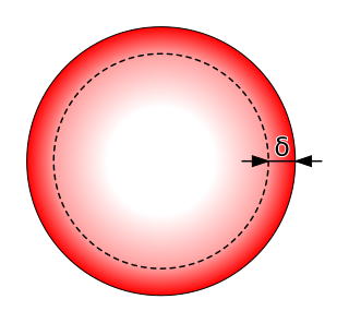
In electromagnetism, skin effect is the tendency of an alternating electric current (AC) to become distributed within a conductor such that the current density is largest near the surface of the conductor and decreases exponentially with greater depths in the conductor. It is caused by opposing eddy currents induced by the changing magnetic field resulting from the alternating current. The electric current flows mainly at the skin of the conductor, between the outer surface and a level called the skin depth. Skin depth depends on the frequency of the alternating current; as frequency increases, current flow becomes more concentrated near the surface, resulting in less skin depth. Skin effect reduces the effective cross-section of the conductor and thus increases its effective resistance. At 60 Hz in copper, skin depth is about 8.5 mm. At high frequencies, skin depth becomes much smaller.

This is an index of articles relating to electronics and electricity or natural electricity and things that run on electricity and things that use or conduct electricity.

<span class="mw-page-title-main">Impedance matching</span> Adjusting input/output impedances of an electrical circuit for some purpose

In electrical engineering, impedance matching is the practice of designing or adjusting the input impedance or output impedance of an electrical device for a desired value. Often, the desired value is selected to maximize power transfer or minimize signal reflection. For example, impedance matching typically is used to improve power transfer from a radio transmitter via the interconnecting transmission line to the antenna. Signals on a transmission line will be transmitted without reflections if the transmission line is terminated with a matching impedance.

<span class="mw-page-title-main">Antenna tuner</span> Telecommunications device

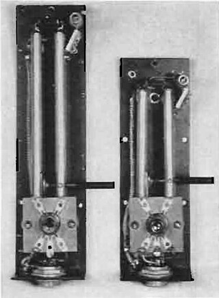
An antenna tuner is a passive electronic device inserted between a radio transmitter and its antenna. Its purpose is to optimize power transfer by matching the impedance of the radio to the signal impedance on the feedline to the antenna.

<span class="mw-page-title-main">Permalloy</span>

Permalloy is a nickel–iron magnetic alloy, with about 80% nickel and 20% iron content. Invented in 1914 by physicist Gustav Elmen at Bell Telephone Laboratories, it is notable for its very high magnetic permeability, which makes it useful as a magnetic core material in electrical and electronic equipment, and also in magnetic shielding to block magnetic fields. Commercial permalloy alloys typically have relative permeability of around 100,000, compared to several thousand for ordinary steel.

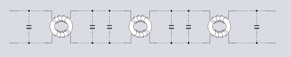
A transmission line which meets the Heaviside condition, named for Oliver Heaviside (1850–1925), and certain other conditions can transmit signals without dispersion and without distortion. The importance of the Heaviside condition is that it showed the possibility of dispersionless transmission of telegraph signals.In some cases, the performance of a transmission line can be improved by adding inductive loading to the cable.

<span class="mw-page-title-main">T-antenna</span> Type of radio antenna

A ‘T’-antenna, ‘T’-aerial, or flat-top antenna is a monopole radio antenna consisting of one or more horizontal wires suspended between two supporting radio masts or buildings and insulated from them at the ends. A vertical wire is connected to the center of the horizontal wires and hangs down close to the ground, connected to the transmitter or receiver. The shape of the antenna resembles the letter "T", hence the name. The transmitter power is applied, or the receiver is connected, between the bottom of the vertical wire and a ground connection.

This is an alphabetical list of articles pertaining specifically to electrical and electronics engineering. For a thematic list, please see List of electrical engineering topics. For a broad overview of engineering, see List of engineering topics. For biographies, see List of engineers.

<span class="mw-page-title-main">Stub (electronics)</span> Short electrical transmission line

In microwave and radio-frequency engineering, a stub or resonant stub is a length of transmission line or waveguide that is connected at one end only. The free end of the stub is either left open-circuit, or short-circuited. Neglecting transmission line losses, the input impedance of the stub is purely reactive; either capacitive or inductive, depending on the electrical length of the stub, and on whether it is open or short circuit. Stubs may thus function as capacitors, inductors and resonant circuits at radio frequencies.

Foster's reactance theorem is an important theorem in the fields of electrical network analysis and synthesis. The theorem states that the reactance of a passive, lossless two-terminal (one-port) network always strictly monotonically increases with frequency. It is easily seen that the reactances of inductors and capacitors individually increase with frequency and from that basis a proof for passive lossless networks generally can be constructed. The proof of the theorem was presented by Ronald Martin Foster in 1924, although the principle had been published earlier by Foster's colleagues at American Telephone & Telegraph.

<span class="mw-page-title-main">Parasitic capacitance</span> Usually unwanted capacitance in a circuit

Parasitic capacitance or stray capacitance is the unavoidable and usually unwanted capacitance that exists between the parts of an electronic component or circuit simply because of their proximity to each other. When two electrical conductors at different voltages are close together, the electric field between them causes electric charge to be stored on them; this effect is capacitance.

<span class="mw-page-title-main">Zobel network</span>

Zobel networks are a type of filter section based on the image-impedance design principle. They are named after Otto Zobel of Bell Labs, who published a much-referenced paper on image filters in 1923. The distinguishing feature of Zobel networks is that the input impedance is fixed in the design independently of the transfer function. This characteristic is achieved at the expense of a much higher component count compared to other types of filter sections. The impedance would normally be specified to be constant and purely resistive. For this reason, Zobel networks are also known as constant resistance networks. However, any impedance achievable with discrete components is possible.

Constant k filters, also k-type filters, are a type of electronic filter designed using the image method. They are the original and simplest filters produced by this methodology and consist of a ladder network of identical sections of passive components. Historically, they are the first filters that could approach the ideal filter frequency response to within any prescribed limit with the addition of a sufficient number of sections. However, they are rarely considered for a modern design, the principles behind them having been superseded by other methodologies which are more accurate in their prediction of filter response.

<span class="mw-page-title-main">George Ashley Campbell</span> American electrical engineer

George Ashley Campbell was an American engineer. He was a pioneer in developing and applying quantitative mathematical methods to the problems of long-distance telegraphy and telephony. His most important contributions were to the theory and implementation of the use of loading coils and the first wave filters designed to what was to become known as the image method. Both these areas of work resulted in important economic advantages for the American Telephone and Telegraph Company (AT&T).

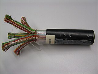
Carl Emil Krarup was a Danish telegraph engineer who is chiefly known for the invention of a kind of loaded cable, eponymously called Krarup cable, which made improvements in the transmission of telephone signals, especially on submarine cables.

Analogue filters are a basic building block of signal processing much used in electronics. Amongst their many applications are the separation of an audio signal before application to bass, mid-range, and tweeter loudspeakers; the combining and later separation of multiple telephone conversations onto a single channel; the selection of a chosen radio station in a radio receiver and rejection of others.

<span class="mw-page-title-main">Primary line constants</span> Parameters of transmission lines

The primary line constants are parameters that describe the characteristics of conductive transmission lines, such as pairs of copper wires, in terms of the physical electrical properties of the line. The primary line constants are only relevant to transmission lines and are to be contrasted with the secondary line constants, which can be derived from them, and are more generally applicable. The secondary line constants can be used, for instance, to compare the characteristics of a waveguide to a copper line, whereas the primary constants have no meaning for a waveguide.

References

  1. Brittain, p. 43
  2. Brittain, p. 42
  3. Mason, p. 409
  4. Bakshi & Bakshi, p. 1.56
  5. Heaviside, O, "Electromagnetic Induction and its propagation", The Electrician, 3 June 1887.
  6. Heaviside, O, Electrical Papers, vol. 1, pp. 139-140, Boston, 1925.
  7. Brittain, pp. 39-40
  8. The Electrician, 1887 and reproduced (according to Brittain) in Heaviside, O, Electromagnetic Theory, p. 112
  9. Brittain, p. 40
  10. Stone, M S, Electric Circuit, US patent 0 578 275, filed 10 September 1896, issued 2 March 1897.
  11. Brittain pp. 40-41
  12. Brittain, pp. 42-45
  13. Brittain, pp. 43-44
  14. Brittain p. 45
  15. Campbell, G A, "Physical Theory of the Electric Wave-Filter", Bell System Tech J, November 1922, vol. 1, no. 2, pp. 1-32.
  16. Brittain, p. 56
  17. Pupin, M, Art of Reducing Attenuation of Electrical Waves and Apparatus Therefor, US patent 0 652 230, filed 14 December 1899, issued 19 June 1900.
  18. Pupin, M, Apparatus for Telegraphic of Telephonic Transmission, US patent 0 519 346, filed 14 December 1893, issued 8 May 1894.
  19. Pupin, M I, From Immigrant to Inventor, pp. 330-331, Charles Schribner & Sons, 1924.
  20. Brittain, p. 46
  21. Brittain, p. 46, quoting a contemporary criticism in Electrical Review and experiments by the GPO showing that the scheme does not work.
  22. Pupin, 1894, p. 5 lines 75-83
  23. Pupin, 1894, p. 5 lines 123-125
  24. Bray, p. 53
  25. Brittain p. 56
  26. Brittain, pp. 36, 48-50
    Behrend to Searle, in letter quoted by Brittain, p37
    Searle to Behrend, 1931, in letter quoted by Brittain, p37
    Nahin, p276
  27. Pupin, M I, Art of Reducing Attenuation of Electrical Waves and Apparatus Therefore, US patent 0 652 230, filed 14 December 1899, issued 19 June 1900.
  28. Brittain, p. 44
  29. Brittain p. 44-45
  30. 1 2 Samuel H. Williamson, "Seven Ways to Compute the Relative Value of a U.S. Dollar Amount, 1774 to present" (Contemporary Standard of Living measure) MeasuringWorth, April 2013.
  31. Brittain, pp. 54, 55 (footnote), 57
  32. Brittain, p. 45
  33. Brittain, p. 36
  34. Shaw, T & Fondiller, W, "Developments and Applications of Loading for Telephone Circuits", Transactions of the American Institute of Electrical Engineers, vol. 45, pp. 291-292, 1926.
  35. Brittain quoting Heaviside letter to Behrend, 1918.
  36. Griffiths, p. 237
  37. Newell, p. 478
  38. Newell, p. 479
  39. Britannica, 1911
  40. Newell, p. 479
  41. Kragh, p. 129
  42. Huurderman, pp. 321-322
  43. 1 2 Huurdeman, p.314
  44. Huurdeman, p. 308
  45. May, pp. 947, 950
  46. Smith, WS, Garnett, HJ, New and improved magnetic alloys, and their application in the manufacture of telegraphic and telephonic cables, Patent GB224972, filed 25 Aug 1923, issued 25 Nov 1925. patented in the US as US1582353 and US1552769
  47. Green
  48. Bakshi & Bakshi, p. 1.55
  49. Green

Bibliography