Repeater

Last updated
A radio repeater retransmits a radio signal. Repeater-schema.svg
A radio repeater retransmits a radio signal.

In telecommunications, a repeater is an electronic device that receives a signal and retransmits it. Repeaters are used to extend transmissions so that the signal can cover longer distances or be received on the other side of an obstruction. Some types of repeaters broadcast an identical signal, but alter its method of transmission, for example, on another frequency or baud rate.

Contents

There are several different types of repeaters; a telephone repeater is an amplifier in a telephone line, an optical repeater is an optoelectronic circuit that amplifies the light beam in an optical fiber cable; and a radio repeater is a radio receiver and transmitter that retransmits a radio signal.

A broadcast relay station is a repeater used in broadcast radio and television.

Overview

When an information-bearing signal passes through a communication channel, it is progressively degraded due to loss of power. For example, when a telephone call passes through a wire telephone line, some of the power in the electric current which represents the audio signal is dissipated as heat in the resistance of the copper wire. The longer the wire, the more power is lost, and the smaller the amplitude of the signal at the far end. So with a long enough wire the call will not be audible at the other end. Similarly, the greater the distance between a radio station and a receiver, the weaker the radio signal, and the poorer the reception. A repeater is an electronic device in a communication channel that increases the power of a signal and retransmits it, allowing it to travel further. Since it amplifies the signal, it requires a source of electric power.

The term "repeater" originated with telegraphy in the 19th century, and referred to an electromechanical device (a relay) used to regenerate telegraph signals. [1] [2]

Use of the term has continued in telephony and data communications.

In computer networking, because repeaters work with the actual physical signal, and do not attempt to interpret the data being transmitted, they operate on the physical layer, the first layer of the OSI model; a multiport Ethernet repeater is usually called a hub.

Types

Telephone repeater

This is used to increase the range of telephone signals in a telephone line.

  • Land line repeater

They are most frequently used in trunklines that carry long distance calls. In an analog telephone line consisting of a pair of wires, it consists of an amplifier circuit made of transistors which use power from a DC current source to increase the power of the alternating current audio signal on the line. Since the telephone is a duplex (bidirectional) communication system, the wire pair carries two audio signals, one going in each direction. So telephone repeaters have to be bilateral, amplifying the signal in both directions without causing feedback, which complicates their design considerably. Telephone repeaters were the first type of repeater and were some of the first applications of amplification. The development of telephone repeaters between 1900 and 1915 made long-distance phone service possible. Now, most telecommunications cables are fiber-optic cables which use optical repeaters (below).

Before the invention of electronic amplifiers, mechanically coupled carbon microphones were used as amplifiers in telephone repeaters. After the turn of the 20th century it was found that negative resistance mercury lamps could amplify, and they were used. [3] The invention of audion tube repeaters around 1916 made transcontinental telephony practical. In the 1930s vacuum tube repeaters using hybrid coils became commonplace, allowing the use of thinner wires. In the 1950s negative impedance gain devices were more popular, and a transistorized version called the E6 repeater was the final major type used in the Bell System before the low cost of digital transmission made all voiceband repeaters obsolete. Frequency frogging repeaters were commonplace in frequency-division multiplexing systems from the middle to late 20th century.

  • Submarine cable repeater

This is a type of telephone repeater used in underwater submarine telecommunications cables.

Optical communications repeater

This is used to increase the range of signals in a fiber-optic cable. Digital information travels through a fiber-optic cable in the form of short pulses of light. The light is made up of particles called photons, which can be absorbed or scattered in the fiber. An optical communications repeater usually consists of a phototransistor which converts the light pulses to an electrical signal, an amplifier to increase the power of the signal, an electronic filter which reshapes the pulses, and a laser which converts the electrical signal to light again and sends it out the other fiber. However, optical amplifiers are being developed for repeaters to amplify the light itself without the need of converting it to an electric signal first.

Radio repeater

A radio communications with a Repeater or a Talkaround channel Repeater Talk around channel.png
A radio communications with a Repeater or a Talkaround channel
Guarini-Foresio's repeater Repetitor Guarini.jpg
Guarini-Foresio's repeater

This is used to extend the range of coverage of a radio signal. The history of radio relay repeaters began in 1898 from the publication by Johann Mattausch in Austrian Journal Zeitschrift für Electrotechnik (v. 16, 35 - 36). [2] [4] But his proposal "Translator" was primitive and not suitable for use. The first relay system with radio repeaters, which really functioned, was that invented in 1899 by Emile Guarini-Foresio. [2]

A radio repeater usually consists of a radio receiver connected to a radio transmitter. The received signal is amplified and retransmitted, often on another frequency, to provide coverage beyond the obstruction. Usage of a duplexer can allow the repeater to use one antenna for both receive and transmit at the same time.

  • Broadcast relay station, rebroadcastor or translator: This is a repeater used to extend the coverage of a radio or television broadcasting station. It consists of a secondary radio or television transmitter. The signal from the main transmitter often comes over leased telephone lines or by microwave relay.
  • Microwave relay : This is a specialized point-to-point telecommunications link, consisting of a microwave receiver that receives information over a beam of microwaves from another relay station in line-of-sight distance, and a microwave transmitter which passes the information on to the next station over another beam of microwaves. Networks of microwave relay stations transmit telephone calls, television programs, and computer data from one city to another over continent-wide areas.
  • Passive repeater : This is a microwave relay that simply consists of a flat metal surface to reflect the microwave beam in another direction. It is used to get microwave relay signals over hills and mountains when it is not necessary to amplify the signal.
  • Cellular repeater : This is a radio repeater for boosting cell phone reception in a limited area. The device functions like a small cellular base station, with a directional antenna to receive the signal from the nearest cell tower, an amplifier, and a local antenna to rebroadcast the signal to nearby cell phones. It is often used in downtown office buildings.
  • Digipeater: A repeater node in a packet radio network. It performs a store and forward function, passing on packets of information from one node to another.
  • Amateur radio repeater : Used by amateur radio operators to enable two-way communication across an area which would otherwise be difficult by point-to-point on VHF and UHF. These repeaters are set up and maintained by individual operators or clubs, and are generally available for any licensed amateur to use. A hill or mountaintop location is a preferable location to construct a repeater, as it will maximize the usability across a large area.

Radio repeaters improve communication coverage in systems using frequencies that typically have line-of-sight propagation. Without a repeater, these systems are limited in range by the curvature of the Earth and the blocking effect of terrain or high buildings. A repeater on a hilltop or tall building can allow stations that are out of each other's line-of-sight range to communicate reliably. [5]

Radio repeaters may also allow translation from one set of radio frequencies to another, for example to allow two different public service agencies to interoperate (say, police and fire services of a city, or neighboring police departments). They may provide links to the public switched telephone network as well, [6] [7] or satellite network (BGAN, INMARSAT, MSAT) as an alternative path from source to the destination. [8]

Typically a repeater station listens on one frequency, A, and transmits on a second, B. All mobile stations listen for signals on channel B and transmit on channel A. The difference between the two frequencies may be relatively small compared to the frequency of operation, say 1%. Often the repeater station will use the same antenna for transmission and reception; highly selective filters called "duplexers" separate the faint incoming received signal from the billions of times more powerful outbound transmitted signal. Sometimes separate transmitting and receiving locations are used, connected by a wire line or a radio link. While the repeater station is designed for simultaneous reception and transmission, mobile units need not be equipped with the bulky and costly duplexers, as they only transmit or receive at any time.

Mobile units in a repeater system may be provided with a "talkaround" channel that allows direct mobile-to-mobile operation on a single channel. This may be used if out of reach of the repeater system, or for communications not requiring the attention of all mobiles. The "talkaround" channel may be the repeater output frequency; the repeater will not retransmit any signals on its output frequency. [9]

An engineered radio communication system designer will analyze the coverage area desired and select repeater locations, elevations, antennas, operating frequencies and power levels to permit a predictable level of reliable communication over the designed coverage area.

Data handling

Repeaters can be divided into two types depending on the type of data they handle:

Analog repeater

This type is used in channels that transmit data in the form of an analog signal in which the voltage or current is proportional to the amplitude of the signal, as in an audio signal. They are also used in trunklines that transmit multiple signals using frequency division multiplexing (FDM). Analog repeaters are composed of a linear amplifier, and may include electronic filters to compensate for frequency and phase distortion in the line.

Digital repeater

The digital repeater is used in channels that transmit data by binary digital signals, in which the data is in the form of pulses with only two possible values, representing the binary digits 1 and 0. A digital repeater amplifies the signal, and it also may retime, resynchronize, and reshape the pulses. A repeater that performs the retiming or resynchronizing functions may be called a regenerator .

See also

Related Research Articles

<span class="mw-page-title-main">Microwave</span> Electromagnetic radiation with wavelengths from 1 m to 1 mm

Microwave is a form of electromagnetic radiation with wavelengths shorter than other radio waves but longer than infrared waves, ranging from about one meter to one millimeter, corresponding to frequencies between 300 MHz and 300 GHz respectively. Different sources define different frequency ranges as microwaves; the above broad definition includes UHF, SHF and EHF bands. A more common definition in radio-frequency engineering is the range between 1 and 100 GHz. In all cases, microwaves include the entire SHF band at minimum. Frequencies in the microwave range are often referred to by their IEEE radar band designations: S, C, X, Ku, K, or Ka band, or by similar NATO or EU designations.

A communications system or communication system is a collection of individual telecommunications networks systems, relay stations, tributary stations, and terminal equipment usually capable of interconnection and interoperation to form an integrated whole. The components of a communications system serve a common purpose, are technically compatible, use common procedures, respond to controls, and operate in union.

<span class="mw-page-title-main">Network topology</span> Arrangement of the elements of a communication network

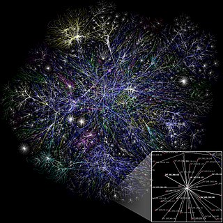
Network topology is the arrangement of the elements of a communication network. Network topology can be used to define or describe the arrangement of various types of telecommunication networks, including command and control radio networks, industrial fieldbusses and computer networks.

In radio communication, a transceiver is an electronic device which is a combination of a radio transmitter and a receiver, hence the name. It can both transmit and receive radio waves using an antenna, for communication purposes. These two related functions are often combined in a single device to reduce manufacturing costs. The term is also used for other devices which can both transmit and receive through a communications channel, such as optical transceivers which transmit and receive light in optical fiber systems, and bus transceivers which transmit and receive digital data in computer data buses.

<span class="mw-page-title-main">Transmission medium</span> Conduit for signal propagation

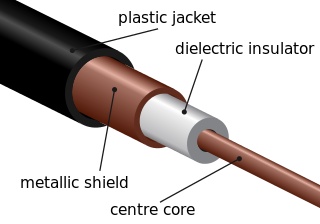
A transmission medium is a system or substance that can mediate the propagation of signals for the purposes of telecommunication. Signals are typically imposed on a wave of some kind suitable for the chosen medium. For example, data can modulate sound, and a transmission medium for sounds may be air, but solids and liquids may also act as the transmission medium. Vacuum or air constitutes a good transmission medium for electromagnetic waves such as light and radio waves. While a material substance is not required for electromagnetic waves to propagate, such waves are usually affected by the transmission media they pass through, for instance, by absorption or reflection or refraction at the interfaces between media. Technical devices can therefore be employed to transmit or guide waves. Thus, an optical fiber or a copper cable is used as transmission media.

There are two types of radio network currently in use around the world: the one-to-many broadcast network commonly used for public information and mass-media entertainment, and the two-way radio type used more commonly for public safety and public services such as police, fire, taxicabs, and delivery services. Cell phones are able to send and receive simultaneously by using two different frequencies at the same time. Many of the same components and much of the same basic technology applies to all three.

<span class="mw-page-title-main">Cable television headend</span> Facility for cable television system

A cable television headend is a master facility for receiving television signals for processing and distribution over a cable television system. A headend facility may be staffed or unstaffed and is typically surrounded by some type of security fencing. The building is typically sturdy and purpose-built to provide security, cooling, and easy access for the electronic equipment used to receive and re-transmit video over the local cable infrastructure. One can also find head ends in power-line communication (PLC) substations and Internet communications networks.

<span class="mw-page-title-main">Base station</span> Type of radio station

Base station is – according to the International Telecommunication Union's (ITU) Radio Regulations (RR) – a "land station in the land mobile service."

A duplex communication system is a point-to-point system composed of two or more connected parties or devices that can communicate with one another in both directions. Duplex systems are employed in many communications networks, either to allow for simultaneous communication in both directions between two connected parties or to provide a reverse path for the monitoring and remote adjustment of equipment in the field. There are two types of duplex communication systems: full-duplex (FDX) and half-duplex (HDX).

<span class="mw-page-title-main">Leaky feeder</span> Communications system used in underground mining and tunnel environments

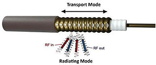
A leaky feeder is a communications system used in underground mining and other tunnel environments. Manufacturers and cabling professionals use the term "radiating cable" as this implies that the cable is designed to radiate: something that coaxial cable is not generally supposed to do.

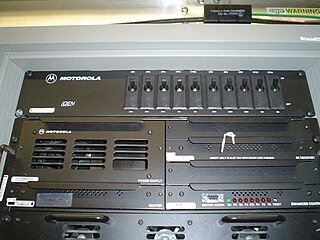
A land mobile radio system (LMRS) is a person-to-person voice communication system consisting of two-way radio transceivers which can be stationary, mobile, or portable.

A radio transmitter or receiver is connected to an antenna which emits or receives the radio waves. The antenna feed system or antenna feed is the cable or conductor, and other associated equipment, which connects the transmitter or receiver with the antenna and makes the two devices compatible. In a radio transmitter, the transmitter generates an alternating current of radio frequency, and the feed system feeds the current to the antenna, which converts the power in the current to radio waves. In a radio receiver, the incoming radio waves excite tiny alternating currents in the antenna, and the feed system delivers this current to the receiver, which processes the signal.

<span class="mw-page-title-main">Amateur radio repeater</span> Combined receiver and transmitter

An amateur radio repeater is an electronic device that receives a weak or low-level amateur radio signal and retransmits it at a higher level or higher power, so that the signal can cover longer distances without degradation. Many repeaters are located on hilltops or on tall buildings as the higher location increases their coverage area, sometimes referred to as the radio horizon, or "footprint". Amateur radio repeaters are similar in concept to those used by public safety entities, businesses, government, military, and more. Amateur radio repeaters may even use commercially packaged repeater systems that have been adjusted to operate within amateur radio frequency bands, but more often amateur repeaters are assembled from receivers, transmitters, controllers, power supplies, antennas, and other components, from various sources.

<span class="mw-page-title-main">Radio repeater</span>

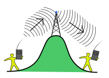
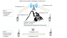
A radio repeater is a combination of a radio receiver and a radio transmitter that receives a signal and retransmits it, so that two-way radio signals can cover longer distances. A repeater sited at a high elevation can allow two mobile stations, otherwise out of line-of-sight propagation range of each other, to communicate. Repeaters are found in professional, commercial, and government mobile radio systems and also in amateur radio.

<span class="mw-page-title-main">Microwave transmission</span> Transmission of information via microwaves

Microwave transmission is the transmission of information by electromagnetic waves with wavelengths in the microwave frequency range of 300 MHz to 300 GHz of the electromagnetic spectrum. Microwave signals are normally limited to the line of sight, so long-distance transmission using these signals requires a series of repeaters forming a microwave relay network. It is possible to use microwave signals in over-the-horizon communications using tropospheric scatter, but such systems are expensive and generally used only in specialist roles.

<span class="mw-page-title-main">Passive repeater</span> Type of radio-signal reflector


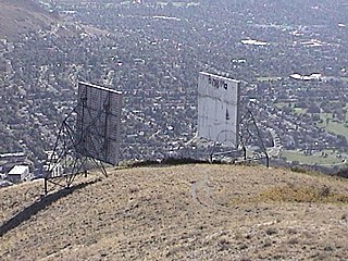
A passive repeater or passive radio link deflection, is a reflective or sometimes refractive panel or other object that assists in closing a radio or microwave link, in places where an obstacle in the signal path blocks any direct, line of sight communication.

<span class="mw-page-title-main">Radio</span> Technology of using radio waves to carry information

Radio is the technology of communicating using radio waves. Radio waves are electromagnetic waves of frequency between 3 hertz (Hz) and 300 gigahertz (GHz). They are generated by an electronic device called a transmitter connected to an antenna which radiates the waves. They are received by another antenna connected to a radio receiver. In addition to communication, radio is used for radar, radio navigation, remote control, remote sensing, and other applications.

Radio over fiber (RoF) or RF over fiber (RFoF) refers to a technology whereby light is modulated by a radio frequency signal and transmitted over an optical fiber link. Main technical advantages of using fiber optical links are lower transmission losses and reduced sensitivity to noise and electromagnetic interference compared to all-electrical signal transmission.

Self-interference cancellation (SIC) is a signal processing technique that enables a radio transceiver to simultaneously transmit and receive on a single channel, a pair of partially-overlapping channels, or any pair of channels in the same frequency band. When used to allow simultaneous transmission and reception on the same frequency, sometimes referred to as “in-band full-duplex” or “simultaneous transmit and receive,” SIC effectively doubles spectral efficiency. SIC also enables devices and platforms containing two radios that use the same frequency band to operate both radios simultaneously.

<span class="mw-page-title-main">Wireless Set Number 10</span> Worlds first microwave relay telephone system

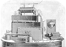
The British Army's Wireless Set, Number 10, was the world's first microwave relay telephone system. It transmitted eight full-duplex (two-way) telephone channels between two stations limited only by the line-of-sight, often on the order of 25 to 50 miles. The stations were mounted in highly mobile trailers and were set up simply by aiming the two parabolic antennas on the roof at the next station.

References

  1. Loring, A. E.E (1878). A Hand-book of the Electro-Magnetic Telegraph. New York: D. Van Nostrand. pp. 53–54.
  2. 1 2 3 Slyusar, Vadym (2015). "First Antennas for Relay Stations" (PDF). International Conference on Antenna Theory and Techniques, 21–24 April 2015. Kharkiv, Ukraine. pp. 254–255. Archived (PDF) from the original on 24 September 2015. Retrieved 10 August 2017.
  3. Sungook, Hong (2001). Wireless: From Marconi's Black-Box to the Audion. MIT Press. p. 165. ISBN   0262082985.
  4. Mattausch J. Telegraphie ohne Draht. Eine Studie. // Zeitschrift für Elektrotechnik. Organ des Elektrotechnischen Vereines in Wien.- Heft 3, 16. Jänner 1898. - XVI. Jahrgang. - S. 35–36. Archived 2017-08-06 at the Wayback Machine
  5. "Radio Awareness about Communications Systems - HOW DO REPEATER SYSTEMS WORK?". .taitradioacademy.com/. 22 October 2014. Archived from the original on 2017-09-04. Retrieved 2017-08-23.
  6. "Radio Interoperability Communications Systems -". basecampconnect.com. Archived from the original on 2017-09-04. Retrieved 2017-08-23.
  7. "Radio Interoperability - TELEPHONE INTERCONNECT-". codanradio.com/. Archived from the original on 2017-09-04. Retrieved 2017-08-23.
  8. "Tactical Voice Communications Solutions for HLD/HLS" (PDF). c-at.com. Archived (PDF) from the original on 2022-10-09. Retrieved 2017-08-23.
  9. Land mobile radio systems - 2nd ed. Improving and Extending Area Coverage (Englewood Cliffs, NJ : PTR Prentice Hall, 1994) ISBN   0131231596, p. 67-75.