
The Fresnel equations describe the reflection and transmission of light when incident on an interface between different optical media. They were deduced by French engineer and physicist Augustin-Jean Fresnel who was the first to understand that light is a transverse wave, when no one realized that the waves were electric and magnetic fields. For the first time, polarization could be understood quantitatively, as Fresnel's equations correctly predicted the differing behaviour of waves of the s and p polarizations incident upon a material interface.
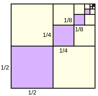
In mathematics, a geometric series is the sum of an infinite number of terms that have a constant ratio between successive terms. For example, the series

In mathematics, the geometric mean is a mean or average which indicates a central tendency of a finite set of real numbers by using the product of their values. The geometric mean is defined as the nth root of the product of n numbers, i.e., for a set of numbers a1, a2, ..., an, the geometric mean is defined as
In physics and electrical engineering the reflection coefficient is a parameter that describes how much of a wave is reflected by an impedance discontinuity in the transmission medium. It is equal to the ratio of the amplitude of the reflected wave to the incident wave, with each expressed as phasors. For example, it is used in optics to calculate the amount of light that is reflected from a surface with a different index of refraction, such as a glass surface, or in an electrical transmission line to calculate how much of the electromagnetic wave is reflected by an impedance discontinuity. The reflection coefficient is closely related to the transmission coefficient. The reflectance of a system is also sometimes called a reflection coefficient.

The reflectance of the surface of a material is its effectiveness in reflecting radiant energy. It is the fraction of incident electromagnetic power that is reflected at the boundary. Reflectance is a component of the response of the electronic structure of the material to the electromagnetic field of light, and is in general a function of the frequency, or wavelength, of the light, its polarization, and the angle of incidence. The dependence of reflectance on the wavelength is called a reflectance spectrum or spectral reflectance curve.
In telecommunications, return loss is a measure in relative terms of the power of the signal reflected by a discontinuity in a transmission line or optical fiber. This discontinuity can be caused by a mismatch between the termination or load connected to the line and the characteristic impedance of the line. It is usually expressed as a ratio in decibels (dB);

In radio engineering and telecommunications, standing wave ratio (SWR) is a measure of impedance matching of loads to the characteristic impedance of a transmission line or waveguide. Impedance mismatches result in standing waves along the transmission line, and SWR is defined as the ratio of the partial standing wave's amplitude at an antinode (maximum) to the amplitude at a node (minimum) along the line.
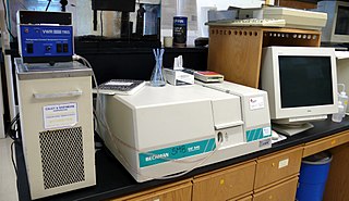
Ultraviolet (UV) spectroscopy or ultraviolet–visible (UV–VIS) spectrophotometry refers to absorption spectroscopy or reflectance spectroscopy in part of the ultraviolet and the full, adjacent visible regions of the electromagnetic spectrum. Being relatively inexpensive and easily implemented, this methodology is widely used in diverse applied and fundamental applications. The only requirement is that the sample absorb in the UV-Vis region, i.e. be a chromophore. Absorption spectroscopy is complementary to fluorescence spectroscopy. Parameters of interest, besides the wavelength of measurement, are absorbance (A) or transmittance (%T) or reflectance (%R), and its change with time.

In electrical engineering, impedance matching is the practice of designing or adjusting the input impedance or output impedance of an electrical device for a desired value. Often, the desired value is selected to maximize power transfer or minimize signal reflection. For example, impedance matching typically is used to improve power transfer from a radio transmitter via the interconnecting transmission line to the antenna. Signals on a transmission line will be transmitted without reflections if the transmission line is terminated with a matching impedance.
Absorbance is defined as "the logarithm of the ratio of incident to transmitted radiant power through a sample ". Alternatively, for samples which scatter light, absorbance may be defined as "the negative logarithm of one minus absorptance, as measured on a uniform sample". The term is used in many technical areas to quantify the results of an experimental measurement. While the term has its origin in quantifying the absorption of light, it is often entangled with quantification of light which is “lost” to a detector system through other mechanisms. What these uses of the term tend to have in common is that they refer to a logarithm of the ratio of a quantity of light incident on a sample or material to that which is detected after the light has interacted with the sample.
In probability theory and statistics, the coefficient of variation (CV), also known as normalized root-mean-square deviation (NRMSD), percent RMS, and relative standard deviation (RSD), is a standardized measure of dispersion of a probability distribution or frequency distribution. It is defined as the ratio of the standard deviation to the mean , and often expressed as a percentage ("%RSD"). The CV or RSD is widely used in analytical chemistry to express the precision and repeatability of an assay. It is also commonly used in fields such as engineering or physics when doing quality assurance studies and ANOVA gauge R&R, by economists and investors in economic models, and in psychology/neuroscience.
Scattering parameters or S-parameters describe the electrical behavior of linear electrical networks when undergoing various steady state stimuli by electrical signals.
Line spectral pairs (LSP) or line spectral frequencies (LSF) are used to represent linear prediction coefficients (LPC) for transmission over a channel. LSPs have several properties that make them superior to direct quantization of LPCs. For this reason, LSPs are very useful in speech coding.
In cryptography, an interpolation attack is a type of cryptanalytic attack against block ciphers.

Paris' law is a crack growth equation that gives the rate of growth of a fatigue crack. The stress intensity factor characterises the load around a crack tip and the rate of crack growth is experimentally shown to be a function of the range of stress intensity seen in a loading cycle. The Paris equation is
The transmission coefficient is used in physics and electrical engineering when wave propagation in a medium containing discontinuities is considered. A transmission coefficient describes the amplitude, intensity, or total power of a transmitted wave relative to an incident wave.
Diffuse reflectance spectroscopy, or diffuse reflection spectroscopy, is a subset of absorption spectroscopy. It is sometimes called remission spectroscopy. Remission is the reflection or back-scattering of light by a material, while transmission is the passage of light through a material. The word remission implies a direction of scatter, independent of the scattering process. Remission includes both specular and diffusely back-scattered light. The word reflection often implies a particular physical process, such as specular reflection.
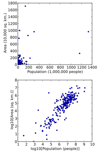
In statistics, data transformation is the application of a deterministic mathematical function to each point in a data set—that is, each data point zi is replaced with the transformed value yi = f(zi), where f is a function. Transforms are usually applied so that the data appear to more closely meet the assumptions of a statistical inference procedure that is to be applied, or to improve the interpretability or appearance of graphs.
Mismatch loss in transmission line theory is the amount of power expressed in decibels that will not be available on the output due to impedance mismatches and signal reflections. A transmission line that is properly terminated, that is, terminated with the same impedance as that of the characteristic impedance of the transmission line, will have no reflections and therefore no mismatch loss. Mismatch loss represents the amount of power wasted in the system. It can also be thought of as the amount of power gained if the system was perfectly matched. Impedance matching is an important part of RF system design; however, in practice there will likely be some degree of mismatch loss. In real systems, relatively little loss is due to mismatch loss and is often on the order of 1dB. According to Walter Maxwell mismatch does not result in any loss, except through the transmission line. This is because the signal reflected from the load is transmitted back to the source, where it is re-reflected due to the reactive impedance presented by the source, back to the load, until all of the signal's power is emitted or absorbed by the load.
In reflection seismology, the anelastic attenuation factor, often expressed as seismic quality factor or Q, quantifies the effects of anelastic attenuation on the seismic wavelet caused by fluid movement and grain boundary friction. As a seismic wave propagates through a medium, the elastic energy associated with the wave is gradually absorbed by the medium, eventually ending up as heat energy. This is known as absorption and will eventually cause the total disappearance of the seismic wave.

