Optical manufacturing and testing

Last updated

Optical manufacturing and testing is the process of manufacturing and testing optical components. It spans a wide range of manufacturing procedures and optical test configurations.

Contents

The manufacture of a conventional spherical lens typically begins with the generation of the optic's rough shape by grinding a glass blank. [1] This can be done, for example, with ring tools. Next, the lens surface is polished to its final form. Typically this is done by lapping—rotating and rubbing the rough lens surface against a tool with the desired surface shape, with a mixture of abrasives and fluid in between. Typically a carved pitch tool is used to polish the surface of a lens. The mixture of abrasive is called slurry and it is typically made from cerium or zirconium oxide in water with lubricants added to facilitate pitch tool movement without sticking to the lens. The particle size in the slurry is adjusted to get the desired shape and finish.

Types of lapping include planetary lapping, double-sided lapping, and cylindrical lapping. [2]

During polishing, the lens may be tested to confirm that the desired shape is being produced, and to ensure that the final shape has the correct form to within the allowed precision. The deviation of an optical surface from the correct shape is typically expressed in fractions of a wavelength, for some convenient wavelength of light (perhaps the wavelength at which the lens is to be used, or a visible wavelength for which a source is available). Inexpensive lenses may have deviations of form as large as several wavelengths (λ, 2λ, etc.). More typical industrial lenses would have deviations no larger than a quarter wavelength (λ/4). Precision lenses for use in applications such as lasers, interferometers, and holography have surfaces with a tenth of a wavelength (λ/10) tolerance or better. In addition to surface profile, a lens must meet requirements for surface quality (scratches, pits, specks, etc.) and accuracy of dimensions.

Fabrication techniques

Unconventional techniques include single-point diamond turning (SPDT) and magnetorheological finishing (MRF). [3]

Free-abrasive grinding

Free-abrasive grinding is a technique to grind down the surface of a material before polishing. It involves the use of small particles of grit to grind away small chips of material from the surface of an optical workpiece. The grit particles are known as free abrasives. The particles are added to a liquid slurry, which goes between a grinding plate and the material. Sliding motions between the grinding plate and the material are used. [4]

After grinding, there is a small amount of surface roughness, which is based on the size of the grit. There is also a small amount of fracturing below the surface of the material, known as subsurface damage (SSD). [4]

To reduce the amount of surface roughness and subsurface damage, additional grinding at a smaller grit size can be done. [4] Typically, two or three stages of grinding are used, with the second and third stages having a size that is decreasing. For example, a typical set of grit stages is 30 micrometer, then 15 micrometer, then 9 micrometer. An alternate set of typical grit stages is 20 micrometer, then 12 micrometer, then 5 micrometer. [4]

Types of abrasives include aluminium oxide, industrial diamond, and silicon carbide. Diamond is typically only used for grinding down very hard materials, or for certain crystals. [5]

Polishing

Optics are polished in a slurry of abrasive particles, a fluid carrier, and optional additives. [6] Types of abrasive particles that can be used include cerium(IV) oxide, diamond, aluminum oxide, and colloidal silica. [6] Optional additives include suspension agents, lubricants, and detergents. [6]

Materials

There are various materials that can be used for optical components, including various types of glass, fused silica, silicon, and crystal quartz. [7] Calcium fluoride (CaF2) can be used as an optical material, although it is easily fractured and scratched. [7]

Materials for infrared optical components include zinc selenide (ZnSe), zinc sulfide (ZnS), and gallium arsenide (GaAs). [7]

Specifications

The specifications for optical components vary based on their type:

Specifications for prisms include pyramidal error, beam path, beam displacement and deviation, base angle, roof edge chips, wavefront, and polarization. [8]

Specifications for aspheric lenses include base radius with tolerance, conic and polynomial coefficients, best-fit sphere reference, sag table reference, sag error tolerance, slope errors versus bandwidth, wavefront per specified test, tilt, and decenter. [8]

Optical coating specifications include apertures, reflection, transmission, absorption, phase shift, adhesion, abrasion resistance, and damage threshold. [8]

In order to avoid the irrecoverable loss of going under minimum thickness, opticians strive to meet all other specifications for an optical component at the maximum allowable thickness within tolerance. [9]

Surface quality

Surface quality is the condition of the surface of an optical component. It indicates the presence of imperfections, such as scratches and pits. [10] It is typically rated according to scratch-dig (S-D) specifications. [11]

Standards for specifying surface quality include the U.S. Military Performance Specification MIL-PRF-13830B and ISO 10110. [10] MIL-PRF-13830B was formerly MIL-O-13830a. Other standards include MIL-C-48497a and MIL-F-48616, which are formally inactive and apply only to coatings. [11] All three of these military standards lack specifications for statistical surface parameters, such as root-mean-square roughness, slope error, and ripple. [11] An extension and improvement to MIL-PRF is the ANSI/OEOSC OP1.002 standard. [11]

Testing techniques

The Fizeau interferometer is the standard type of interferometer that is used in optical fabrication. [12]

Stitching interferometry can be used for testing aspheres. It involves performing subaperture tests that are stitched together into a single-high resolution image. [13]

See also

Notes and references

  1. Shorey, Aric B.; Golini, Don; Kordonski, William (October 2007). "Surface finishing of complex optics". Optics and Photonics News. Optical Society of America. 18 (10): 14–16.
  2. Williamson, Ray (2011). Field guide to optical fabrication. SPIE field guides. Bellingham, Wash: SPIE Press. pp. 45–48. ISBN   978-0-8194-8676-9.
  3. Williamson, Ray (2011). Field guide to optical fabrication. SPIE field guides. Bellingham, Wash: SPIE Press. ISBN   978-0-8194-8676-9.
  4. 1 2 3 4 Williamson, Ray (2011). Field guide to optical fabrication. SPIE field guides. Bellingham, Wash: SPIE Press. p. 26. ISBN   978-0-8194-8676-9.
  5. Williamson, Ray (2011). Field guide to optical fabrication. SPIE field guides. Bellingham, Wash: SPIE Press. p. 27. ISBN   978-0-8194-8676-9.
  6. 1 2 3 Williamson, Ray (2011). Field guide to optical fabrication. SPIE field guides. Bellingham, Wash: SPIE Press. p. 38. ISBN   978-0-8194-8676-9.
  7. 1 2 3 Williamson, Ray (2011). Field guide to optical fabrication. SPIE field guides. Bellingham, Wash: SPIE Press. p. 8. ISBN   978-0-8194-8676-9.
  8. 1 2 3 Williamson, Ray (2011). Field guide to optical fabrication. SPIE field guides. Bellingham, Wash: SPIE Press. p. 10. ISBN   978-0-8194-8676-9.
  9. Williamson, Ray (2011). Field guide to optical fabrication. SPIE field guides. Bellingham, Wash: SPIE Press. p. 11. ISBN   978-0-8194-8676-9.
  10. 1 2 "Understanding Surface Quality Specifications". Edmund Optics. Archived from the original on December 16, 2023.
  11. 1 2 3 4 Williamson, Ray (2011). Field guide to optical fabrication. SPIE field guides. Bellingham, Wash: SPIE Press. p. 7. ISBN   978-0-8194-8676-9.
  12. Williamson, Ray (2011). Field guide to optical fabrication. SPIE field guides. Bellingham, Wash: SPIE Press. p. 87. ISBN   978-0-8194-8676-9.
  13. Williamson, Ray (2011). Field guide to optical fabrication. SPIE field guides. Bellingham, Wash: SPIE Press. p. 12. ISBN   978-0-8194-8676-9.

Related Research Articles

<span class="mw-page-title-main">Optics</span> Branch of physics that studies light

Optics is the branch of physics that studies the behaviour and properties of light, including its interactions with matter and the construction of instruments that use or detect it. Optics usually describes the behaviour of visible, ultraviolet, and infrared light. Light is a type of electromagnetic radiation, and other forms of electromagnetic radiation such as X-rays, microwaves, and radio waves exhibit similar properties.

Photolithography is a process used in the manufacturing of integrated circuits. It involves using light to transfer a pattern onto a substrate, typically a silicon wafer.

<span class="mw-page-title-main">Numerical aperture</span> Characteristic of an optical system

In optics, the numerical aperture (NA) of an optical system is a dimensionless number that characterizes the range of angles over which the system can accept or emit light. By incorporating index of refraction in its definition, NA has the property that it is constant for a beam as it goes from one material to another, provided there is no refractive power at the interface. The exact definition of the term varies slightly between different areas of optics. Numerical aperture is commonly used in microscopy to describe the acceptance cone of an objective, and in fiber optics, in which it describes the range of angles within which light that is incident on the fiber will be transmitted along it.

The focal length of an optical system is a measure of how strongly the system converges or diverges light; it is the inverse of the system's optical power. A positive focal length indicates that a system converges light, while a negative focal length indicates that the system diverges light. A system with a shorter focal length bends the rays more sharply, bringing them to a focus in a shorter distance or diverging them more quickly. For the special case of a thin lens in air, a positive focal length is the distance over which initially collimated (parallel) rays are brought to a focus, or alternatively a negative focal length indicates how far in front of the lens a point source must be located to form a collimated beam. For more general optical systems, the focal length has no intuitive meaning; it is simply the inverse of the system's optical power.

<span class="mw-page-title-main">Dioptre</span> Unit of measurement of optical power

A dioptre or diopter, symbol dpt, is a unit of measurement with dimension of reciprocal length, equivalent to one reciprocal metre, 1 dpt = 1 m−1. It is normally used to express the optical power of a lens or curved mirror, which is a physical quantity equal to the reciprocal of the focal length, expressed in metres. For example, a 3-dioptre lens brings parallel rays of light to focus at 13 metre. A flat window has an optical power of zero dioptres, as it does not cause light to converge or diverge. Dioptres are also sometimes used for other reciprocals of distance, particularly radii of curvature and the vergence of optical beams.

<span class="mw-page-title-main">Optical engineering</span> Field of engineering encompassing light

Optical engineering is the field of science and engineering encompassing the physical phenomena and technologies associated with the generation, transmission, manipulation, detection, and utilization of light. Optical engineers use optics to solve problems and to design and build devices that make light do something useful. They design and operate optical equipment that uses the properties of light using physics and chemistry, such as lenses, microscopes, telescopes, lasers, sensors, fiber-optic communication systems and optical disc systems.

<span class="mw-page-title-main">Astigmatism (optical systems)</span> Optical aberration

An optical system with astigmatism is one where rays that propagate in two perpendicular planes have different foci. If an optical system with astigmatism is used to form an image of a cross, the vertical and horizontal lines will be in sharp focus at two different distances. The term comes from the Greek α- (a-) meaning "without" and στίγμα (stigma), "a mark, spot, puncture".

<span class="mw-page-title-main">Diamond turning</span> Method for making advanced optical elements

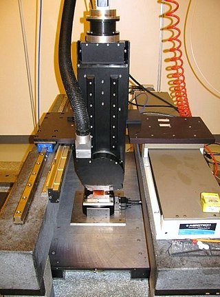
Diamond turning is turning using a cutting tool with a diamond tip. It is a process of mechanical machining of precision elements using lathes or derivative machine tools equipped with natural or synthetic diamond-tipped tool bits. The term single-point diamond turning (SPDT) is sometimes applied, although as with other lathe work, the "single-point" label is sometimes only nominal. The process of diamond turning is widely used to manufacture high-quality aspheric optical elements from crystals, metals, acrylic, and other materials. Plastic optics are frequently molded using diamond turned mold inserts. Optical elements produced by the means of diamond turning are used in optical assemblies in telescopes, video projectors, missile guidance systems, lasers, scientific research instruments, and numerous other systems and devices. Most SPDT today is done with computer numerical control (CNC) machine tools. Diamonds also serve in other machining processes, such as milling, grinding, and honing. Diamond turned surfaces have a high specular brightness and require no additional polishing or buffing, unlike other conventionally machined surfaces.

<span class="mw-page-title-main">Lapping</span> Process of removing material from two workpieces

Lapping is a machining process in which two surfaces are rubbed together with an abrasive between them, by hand movement or using a machine.

<span class="mw-page-title-main">Metallography</span> Study of metals using microscopy

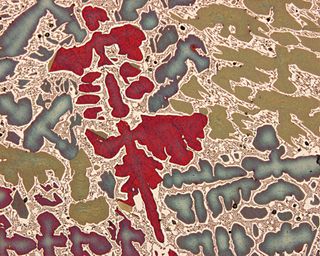
Metallography is the study of the physical structure and components of metals, by using microscopy.

<span class="mw-page-title-main">Sharpening stone</span> Abrasive slab used to sharpen tools

Sharpening stones, or whetstones, are used to sharpen the edges of steel tools such as knives through grinding and honing.

<span class="mw-page-title-main">Paraxial approximation</span> Small angle approximation in geometric optics

In geometric optics, the paraxial approximation is a small-angle approximation used in Gaussian optics and ray tracing of light through an optical system.

<span class="mw-page-title-main">Aspheric lens</span> Type of lens

An aspheric lens or asphere is a lens whose surface profiles are not portions of a sphere or cylinder. In photography, a lens assembly that includes an aspheric element is often called an aspherical lens.

<span class="mw-page-title-main">Entrance pupil</span>

In an optical system, the entrance pupil is the optical image of the physical aperture stop, as 'seen' through the front of the lens system. The corresponding image of the aperture as seen through the back of the lens system is called the exit pupil. If there is no lens in front of the aperture, the entrance pupil's location and size are identical to those of the aperture. Optical elements in front of the aperture will produce a magnified or diminished image that is displaced from the location of the physical aperture. The entrance pupil is usually a virtual image: it lies behind the first optical surface of the system.

<span class="mw-page-title-main">Optical power</span> Degree to which an optical system converges or diverges light

In optics, optical power is the degree to which a lens, mirror, or other optical system converges or diverges light. It is equal to the reciprocal of the focal length of the device: P = 1/f. High optical power corresponds to short focal length. The SI unit for optical power is the inverse metre (m−1), which is commonly called the dioptre.

<span class="mw-page-title-main">Ray (optics)</span> Idealized model of light

In optics, a ray is an idealized geometrical model of light or other electromagnetic radiation, obtained by choosing a curve that is perpendicular to the wavefronts of the actual light, and that points in the direction of energy flow. Rays are used to model the propagation of light through an optical system, by dividing the real light field up into discrete rays that can be computationally propagated through the system by the techniques of ray tracing. This allows even very complex optical systems to be analyzed mathematically or simulated by computer. Ray tracing uses approximate solutions to Maxwell's equations that are valid as long as the light waves propagate through and around objects whose dimensions are much greater than the light's wavelength. Ray optics or geometrical optics does not describe phenomena such as diffraction, which require wave optics theory. Some wave phenomena such as interference can be modeled in limited circumstances by adding phase to the ray model.

<span class="mw-page-title-main">Optical fiber</span> Light-conducting fiber

An optical fiber, or optical fibre in Commonwealth English, is a flexible glass or plastic fiber that can transmit light from one end to the other. Such fibers find wide usage in fiber-optic communications, where they permit transmission over longer distances and at higher bandwidths than electrical cables. Fibers are used instead of metal wires because signals travel along them with less loss and are immune to electromagnetic interference. Fibers are also used for illumination and imaging, and are often wrapped in bundles so they may be used to carry light into, or images out of confined spaces, as in the case of a fiberscope. Specially designed fibers are also used for a variety of other applications, such as fiber optic sensors and fiber lasers.

Sculptured thin films (STFs) are nanostructured materials with unidirectionally varying properties that can be designed and realized in a controllable manner using variants of physical vapor deposition. The ability to virtually instantaneously change the growth direction of their columnar morphology, through simple variations in the direction of the incident vapor flux, leads to a wide spectrum of columnar forms.

<span class="mw-page-title-main">Athermalization</span> Process of achieving optothermal stability in optomechanical systems

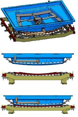
Athermalization, in the field of optics, is the process of achieving optothermal stability in optomechanical systems. This is done by minimizing variations in optical performance over a range of temperatures.

<span class="mw-page-title-main">Precision glass moulding</span> Production of optical glass without grinding and polishing

Precision glass moulding is a replicative process that allows the production of high precision optical components from glass without grinding and polishing. The process is also known as ultra-precision glass pressing. It is used to manufacture precision glass lenses for consumer products such as digital cameras, and high-end products like medical systems. The main advantage over mechanical lens production is that complex lens geometries such as aspheres can be produced cost-efficiently.