
Microscopy is the technical field of using microscopes to view objects and areas of objects that cannot be seen with the naked eye. There are three well-known branches of microscopy: optical, electron, and scanning probe microscopy, along with the emerging field of X-ray microscopy.

A microscope is a laboratory instrument used to examine objects that are too small to be seen by the naked eye. Microscopy is the science of investigating small objects and structures using a microscope. Microscopic means being invisible to the eye unless aided by a microscope.

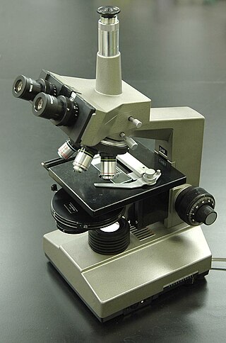
The optical microscope, also referred to as a light microscope, is a type of microscope that commonly uses visible light and a system of lenses to generate magnified images of small objects. Optical microscopes are the oldest design of microscope and were possibly invented in their present compound form in the 17th century. Basic optical microscopes can be very simple, although many complex designs aim to improve resolution and sample contrast.

In optics, any optical instrument or system – a microscope, telescope, or camera – has a principal limit to its resolution due to the physics of diffraction. An optical instrument is said to be diffraction-limited if it has reached this limit of resolution performance. Other factors may affect an optical system's performance, such as lens imperfections or aberrations, but these are caused by errors in the manufacture or calculation of a lens, whereas the diffraction limit is the maximum resolution possible for a theoretically perfect, or ideal, optical system.

A fluorescence microscope is an optical microscope that uses fluorescence instead of, or in addition to, scattering, reflection, and attenuation or absorption, to study the properties of organic or inorganic substances. "Fluorescence microscope" refers to any microscope that uses fluorescence to generate an image, whether it is a simple set up like an epifluorescence microscope or a more complicated design such as a confocal microscope, which uses optical sectioning to get better resolution of the fluorescence image.

Confocal microscopy, most frequently confocal laser scanning microscopy (CLSM) or laser scanning confocal microscopy (LSCM), is an optical imaging technique for increasing optical resolution and contrast of a micrograph by means of using a spatial pinhole to block out-of-focus light in image formation. Capturing multiple two-dimensional images at different depths in a sample enables the reconstruction of three-dimensional structures within an object. This technique is used extensively in the scientific and industrial communities and typical applications are in life sciences, semiconductor inspection and materials science.
Metallography is the study of the physical structure and components of metals, by using microscopy.

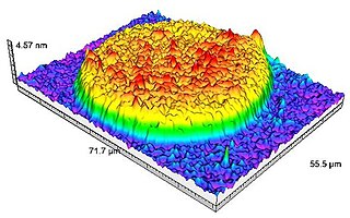
Near-field scanning optical microscopy (NSOM) or scanning near-field optical microscopy (SNOM) is a microscopy technique for nanostructure investigation that breaks the far field resolution limit by exploiting the properties of evanescent waves. In SNOM, the excitation laser light is focused through an aperture with a diameter smaller than the excitation wavelength, resulting in an evanescent field on the far side of the aperture. When the sample is scanned at a small distance below the aperture, the optical resolution of transmitted or reflected light is limited only by the diameter of the aperture. In particular, lateral resolution of 6 nm and vertical resolution of 2–5 nm have been demonstrated.

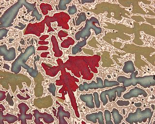
In optical mineralogy and petrography, a thin section is a thin slice of a rock or mineral sample, prepared in a laboratory, for use with a polarizing petrographic microscope, electron microscope and electron microprobe. A thin sliver of rock is cut from the sample with a diamond saw and ground optically flat. It is then mounted on a glass slide and then ground smooth using progressively finer abrasive grit until the sample is only 30 μm thick. The method uses the Michel-Lévy interference colour chart to determine thickness, typically using quartz as the thickness gauge because it is one of the most abundant minerals.
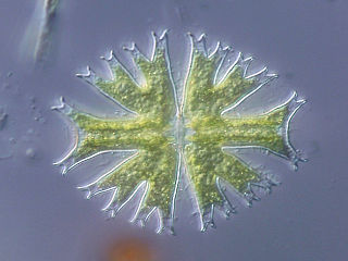
Differential interference contrast (DIC) microscopy, also known as Nomarski interference contrast (NIC) or Nomarski microscopy, is an optical microscopy technique used to enhance the contrast in unstained, transparent samples. DIC works on the principle of interferometry to gain information about the optical path length of the sample, to see otherwise invisible features. A relatively complex optical system produces an image with the object appearing black to white on a grey background. This image is similar to that obtained by phase contrast microscopy but without the bright diffraction halo. The technique was invented by Francis Hughes Smith. The "Smith DIK" was produced by Ernst Leitz Wetzlar in Germany and was difficult to manufacture. DIC was then developed further by Polish physicist Georges Nomarski in 1952.

Dark-field microscopy describes microscopy methods, in both light and electron microscopy, which exclude the unscattered beam from the image. Consequently, the field around the specimen is generally dark.

Bright-field microscopy (BF) is the simplest of all the optical microscopy illumination techniques. Sample illumination is transmitted white light, and contrast in the sample is caused by attenuation of the transmitted light in dense areas of the sample. Bright-field microscopy is the simplest of a range of techniques used for illumination of samples in light microscopes, and its simplicity makes it a popular technique. The typical appearance of a bright-field microscopy image is a dark sample on a bright background, hence the name.
Phase-contrast microscopy (PCM) is an optical microscopy technique that converts phase shifts in light passing through a transparent specimen to brightness changes in the image. Phase shifts themselves are invisible, but become visible when shown as brightness variations.
Köhler illumination is a method of specimen illumination used for transmitted and reflected light optical microscopy. Köhler illumination acts to generate an even illumination of the sample and ensures that an image of the illumination source is not visible in the resulting image. Köhler illumination is the predominant technique for sample illumination in modern scientific light microscopy. It requires additional optical elements which are more expensive and may not be present in more basic light microscopes.

Optical sectioning is the process by which a suitably designed microscope can produce clear images of focal planes deep within a thick sample. This is used to reduce the need for thin sectioning using instruments such as the microtome. Many different techniques for optical sectioning are used and several microscopy techniques are specifically designed to improve the quality of optical sectioning.
Sarfus is an optical quantitative imaging technique based on the association of:

In optical mineralogy, an interference colour chart, also known as the Michel-Levy chart, is a tool first developed by Auguste Michel-Lévy to identify minerals in thin section using a petrographic microscope. With a known thickness of the thin section, minerals have specific and predictable colours in cross-polarized light, and this chart can help identify minerals. The colours are produced by the difference in speed in the fast and slow rays, also known as birefringence.

Interference reflection microscopy (IRM), also called Reflection Interference Contrast Microscopy (RICM) or Reflection Contrast Microscopy (RCM) depending on the context, is an optical microscopy technique that leverages interference effects to form an image of an object on a glass surface. The intensity of the signal is a measure of proximity of the object to the glass surface. This technique can be used to study events at the cell membrane without the use of a (fluorescent) label as is the case for TIRF microscopy.
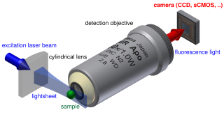
Light sheet fluorescence microscopy (LSFM) is a fluorescence microscopy technique with an intermediate-to-high optical resolution, but good optical sectioning capabilities and high speed. In contrast to epifluorescence microscopy only a thin slice of the sample is illuminated perpendicularly to the direction of observation. For illumination, a laser light-sheet is used, i.e. a laser beam which is focused only in one direction. A second method uses a circular beam scanned in one direction to create the lightsheet. As only the actually observed section is illuminated, this method reduces the photodamage and stress induced on a living sample. Also the good optical sectioning capability reduces the background signal and thus creates images with higher contrast, comparable to confocal microscopy. Because light sheet fluorescence microscopy scans samples by using a plane of light instead of a point, it can acquire images at speeds 100 to 1,000 times faster than those offered by point-scanning methods.
Lattice light-sheet microscopy is a modified version of light sheet fluorescence microscopy that increases image acquisition speed while decreasing damage to cells caused by phototoxicity. This is achieved by using a structured light sheet to excite fluorescence in successive planes of a specimen, generating a time series of 3D images which can provide information about dynamic biological processes.
