
An electrical insulator is a material in which electric current does not flow freely. The atoms of the insulator have tightly bound electrons which cannot readily move. Other materials—semiconductors and conductors—conduct electric current more easily. The property that distinguishes an insulator is its resistivity; insulators have higher resistivity than semiconductors or conductors. The most common examples are non-metals.

A transformer is a passive component that transfers electrical energy from one electrical circuit to another circuit, or multiple circuits. A varying current in any coil of the transformer produces a varying magnetic flux in the transformer's core, which induces a varying electromotive force (EMF) across any other coils wound around the same core. Electrical energy can be transferred between separate coils without a metallic (conductive) connection between the two circuits. Faraday's law of induction, discovered in 1831, describes the induced voltage effect in any coil due to a changing magnetic flux encircled by the coil.

Alternating current (AC) is an electric current which periodically reverses direction and changes its magnitude continuously with time, in contrast to direct current (DC), which flows only in one direction. Alternating current is the form in which electric power is delivered to businesses and residences, and it is the form of electrical energy that consumers typically use when they plug kitchen appliances, televisions, fans and electric lamps into a wall socket. The abbreviations AC and DC are often used to mean simply alternating and direct, respectively, as when they modify current or voltage.
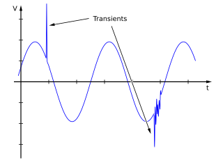
In electrical engineering, spikes are fast, short duration electrical transients in voltage, current, or transferred energy in an electrical circuit.

A surge protector (or spike suppressor, surge suppressor, surge diverter, surge protection device or transient voltage surge suppressor is an appliance or device intended to protect electrical devices in alternating current circuits from voltage spikes, which can arise from a variety of causes including lightning strikes in the vicinity and have a very short duration measured in microseconds.
In electrical engineering, partial discharge (PD) is a localized dielectric breakdown (DB) of a small portion of a solid or fluid electrical insulation (EI) system under high voltage (HV) stress. While a corona discharge (CD) is usually revealed by a relatively steady glow or brush discharge (BD) in air, partial discharges within solid insulation system are not visible.

An isolation transformer is a transformer used to transfer electrical power from a source of alternating current (AC) power to some equipment or device while isolating the powered device from the power source, usually for safety reasons or to reduce transients and harmonics. Isolation transformers provide galvanic isolation; no conductive path is present between source and load. This isolation is used to protect against electric shock, to suppress electrical noise in sensitive devices, or to transfer power between two circuits which must not be connected. A transformer sold for isolation is often built with special insulation between primary and secondary, and is specified to withstand a high voltage between windings.

A current transformer (CT) is a type of transformer that is used to reduce or multiply an alternating current (AC). It produces a current in its secondary which is proportional to the current in its primary.
Transformer oil or insulating oil is an oil that is stable at high temperatures and has excellent electrical insulating properties. It is used in oil-filled wet transformers, some types of high-voltage capacitors, fluorescent lamp ballasts, and some types of high-voltage switches and circuit breakers. Its functions are to insulate, suppress corona discharge and arcing, and to serve as a coolant.
This is an alphabetical list of articles pertaining specifically to electrical and electronics engineering. For a thematic list, please see List of electrical engineering topics. For a broad overview of engineering, see List of engineering topics. For biographies, see List of engineers.

In electric power, a bushing is a hollow electrical insulator that allows an electrical conductor to pass safely through a conducting barrier such as the case of a transformer or circuit breaker without making electrical contact with it. Bushings are typically made from porcelain, though other insulating materials are also used.

Arcing horns are projecting conductors used to protect insulators or switch hardware on high voltage electric power transmission systems from damage during flashover. Overvoltages on transmission lines, due to atmospheric electricity, lightning strikes, or electrical faults, can cause arcs across insulators (flashovers) that can damage them. Alternately, atmospheric conditions or transients that occur during switching can cause an arc to form in the breaking path of a switch during its operation. Arcing horns provide a path for flashover to occur that bypasses the surface of the protected device. Horns are normally paired on either side of an insulator, one connected to the high voltage part and the other to ground, or at the breaking point of a switch contact. They are frequently to be seen on insulator strings on overhead lines, or protecting transformer bushings.
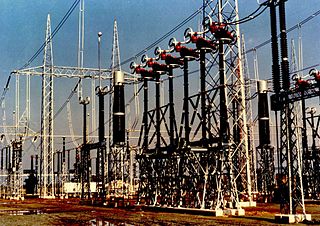
High voltage switchgear is any switchgear used to connect or disconnect a part of a high-voltage power system. This equipment is essential for the protection and safe operation, without interruption, of a high voltage power system, and is important because it is directly linked to the quality of the electricity supply.
Voltage optimisation is a term given to the systematic controlled reduction in the voltages received by an energy consumer to reduce energy use, power demand and reactive power demand. While some voltage 'optimisation' devices have a fixed voltage adjustment, others electronically regulate the voltage automatically.

The gyrator–capacitor model - sometimes also the capacitor-permeance model - is a lumped-element model for magnetic circuits, that can be used in place of the more common resistance–reluctance model. The model makes permeance elements analogous to electrical capacitance rather than electrical resistance. Windings are represented as gyrators, interfacing between the electrical circuit and the magnetic model.
VLF cable testing is a technique for testing of medium and high voltage cables. VLF systems are advantageous in that they can be manufactured to be small and lightweight; making them useful – especially for field testing where transport and space can be issues. Because the inherent capacitance of a power cable needs to be charged when energised, system frequency voltage sources are much larger, heavier and more expensive than their lower-frequency alternatives. Traditionally DC hipot testing was used for field testing of cables, but DC testing has been shown to be ineffective for withstand testing of modern cables with polymer based insulation. DC testing has also been shown to reduce the remaining life of cables with aged polymer insulation.

In electrical engineering, the Korndorfer starter is a technique used for reduced voltage soft starting of induction motors. The circuit uses a three-phase autotransformer and three three-phase switches. This motor starting method has been updated and improved by Hilton Raymond Bacon.

Film capacitors, plastic film capacitors, film dielectric capacitors, or polymer film capacitors, generically called film caps as well as power film capacitors, are electrical capacitors with an insulating plastic film as the dielectric, sometimes combined with paper as carrier of the electrodes.
Condition monitoring of transformers in electrical engineering is the process of acquiring and processing data related to various parameters of transformers to determine their state of quality and predict their failure. This is done by observing the deviation of the transformer parameters from their expected values. Transformers are the most critical assets of electrical transmission and distribution systems, and their failures could cause power outages, personal and environmental hazards, and expensive rerouting or purchase of power from other suppliers. Identifying a transformer which is near failure can allow it to be replaced under controlled conditions at a non-critical time and avoid a system failure.
Transformer oil, a type of insulating and cooling oil used in transformers and other electrical equipment, needs to be tested periodically to ensure that it is still fit for purpose. This is because it tends to deteriorate over time. Testing sequences and procedures are defined by various international standards, many of them set by ASTM. Transformer oil testing consists of measuring breakdown voltage and other physical and chemical properties of samples of the oil, either in a laboratory or using portable test equipment on-site.


