The Type 271 was a surface search radar used by the Royal Navy and allies during World War II. The first widely used naval microwave-frequency system, it was equipped with an antenna small enough to allow it to be mounted on small ships like corvettes and frigates, while its improved resolution over earlier radars allowed it to pick up a surfaced U-boat at around 3 miles (4.8km) and its periscope alone at 900 yards (820m).
The prototype, 271X, was fitted to HMS Orchis in March 1941 and declared operational in May. Small numbers became available during the year, with about thirty sets in operation by October. The design spawned two larger versions, Type 272 for destroyers and small cruisers, and Type 273 for larger cruisers and battleships. The 272 was not considered successful and not widely used. The 273 differed in having larger and more focused antennas, providing higher gain and thus longer range. This proved very successful and was widely used.
By the late-war period, improved versions of all of these designs were introduced. Originally known as the Mark V models, in March 1943 these were renamed Type 277, 276 and 293. These new models were retrofitted as ships came in for servicing and were widespread by late 1944. Type 271Q models remained in service on a number of ships in the post-war period, generally passing out of service with the ships that carried them.
History
Background
The Royal Navy learned of Robert Watson-Watt's radar experiments in 1935 and began exploring the use of radar for naval uses very quickly. In contrast to the Air Ministry, which had no formal electronics establishment at the time, the Navy's Experimental Department in Portsmouth was a powerhouse in electronics design and was able to quickly develop a series of radars for naval use. In 1938, their Type 79 radar was the first naval radar to enter service.[1]
At the time, the only high-power radio frequency electronics operated in the shortwave bands, with wavelengths measured in metres. Existing valves (vacuum tubes) could operate at an absolute maximum of 600MHz (50cm wavelength), but operation anywhere near this range resulted in very low efficiency and output power.[2] Most efforts worked on much longer wavelengths, several metres or more, where commercial electronics for shortwave broadcasts already existed.[3]
For a variety of reasons, antennas have to be a certain size relative to the wavelength of their signals, with the half-wave dipole being a common design. This meant that the radar antennas of this era had to be metres across to have reasonable performance. The prototype Type 79X, which was fitted experimentally to the minesweeperHMS Saltburn in October 1936, used a 4m wavelength that required the antennas to be strung between the ship's masts. It could only be aimed by turning the entire ship. To improve power, a version with an even longer 7m wavelength was developed for HMS Sheffield that provided between 15 and 20kW of power. Its antenna could be rotated, but was enormous and heavy.[4]
Magnetron
The cavity magnetron revolutionized radar development.
In February 1940, John Randall and Harry Boot built a working cavity magnetron, which soon produced 1kW of power at a wavelength of only 10cm from a device about the size of a shoe box. A half-wave dipole for this wavelength was only 5 centimetres (2.0in) long, and could easily be fitted to almost any ship or aircraft. It represented an enormous leap in performance, and microwave radar development by all of the forces began immediately. While the magnetron solved the problem of generating short-wavelength signals with high power, that alone does not make a complete radar system. One also needs a radio signal detector that can operate at equally high frequencies, cables capable of carrying that signal to the antenna efficiently, and a host of other developments.[5]
The Navy was in a particularly good position to take advantage of the magnetron, as part of their Experimental Department was the Valve Laboratory. In 1939, the Valve Laboratory was put in charge of the Committee for the Coordination of Valve Development (CDV), leading the development of new valve technology for all of the UK's armed forces. The Valve Laboratory led development of the tunable reflex klystron that provided the needed intermediate frequency signal for a superheterodyne receiver that operated at microwave frequencies, while the Telecommunications Research Establishment (TRE), the Air Ministry's research arm, introduced a silicon-tungsten crystal detector that generated the appropriate high-frequency signals for the reflex klystron.[5]
By July 1940, samples of all of these devices had arrived at the TRE's experimental shops, along with more powerful magnetrons working between 5 and 10kW. Herbert Skinner cobbled together the various parts on a table to produce the first working microwave radar. This used the updated NT98 magnetron that produced 5kW of power. They demonstrated it by having someone ride a bicycle in front of the device while holding a metal plate. This test demonstrated the new radar's ability to pick up targets even when they were very close to the horizon, something previous designs could not do. Development of production radars using this basic design was undertaken immediately by the Air Ministry and Admiralty.[5]
From 1940 the possibility of air attack on the Experimental Department was considered serious, but it was not until late that year that a move was initiated. In March 1941, the Experimental Department became the Admiralty Signal Establishment (ASE), a name it retained for the rest of the war period. In August, the ASE moved to Lythe Hill House in Haslemere, closer to London.[6]
A report on the state of the ongoing U-boat war in September noted that 70% of all successful attacks by U-boats were made at night and on the surface. This was possible because Asdic could not detect a surfaced submarine, and the radars available at that time were too large to be fitted to the most common escorts.[7] During this wide-ranging "Trade Protection Meeting", the call for "An efficient radar set for anti-submarine surface and air escorts must be developed" was approved by the Prime Minister and given the highest national priority.[7]
In October 1940 a team from the ASE under the direction of Stenhard Landale was sent to the TRE's labs in Swanage to study their lash-up devices.[8] By this time the TRE had two systems in operation and the second could be mounted on a trailer. When tested on the sea-side cliff near the labs, this radar successfully detected small ships in Swanage Bay. The Navy team developed their own version of the prototype, known only as "Apparatus C", which was tested for the first time on the trailer on 8 December 1940.[9]
The antenna, consisting of two parabolic reflectors, worked well on the top of a cliff, but would not work well nearer to the surface as it would be in the case of a mounting on a ship. In this case the low angle between the antenna and waves on the sea would cause spurious returns, or "clutter", that could hide a target. Herbert Skinner, who was leading antenna development at the TRE, took it upon himself to test the existing designs at various altitudes. During a series of tests between 15 and 17 December, Skinner used the TRE's "Apparatus B" against the small ship Titlark and demonstrated tracking at 9 miles (14km) at the top of the 250 foot (76m) cliff, 5 miles (8.0km) at the 60 foot (18m) Peveril Point, and 3.5 miles (5.6km) at 20 feet (6.1m).[9]
Another problem would be keeping the signal from the tightly focused pencil beams on the target as the ship rolled and pitched in the sea. Bernard Lovell suggested the solution would be to use an antenna that had a narrow horizontal beam like the parabolas they were using, but little vertical focussing. This would create a fan-shaped beam spread over about 80degrees vertically that would continue to paint the target as the radar-carrying ship moved in the waves.[9] The resulting design became known as a "cheese antenna" due to it looking like a section cut from a cheese wheel. A prototype was mounted to the admiralty trailer on 19 December and towed to the beach for testing.[10]
271X
Some sense of the urgency of the development program can be seen in the fact that an order for 12 sets had already been placed with the Admiralty's communications laboratory at Eastney (outside Portsmouth). Initially known simply as the Type 271, these models were later referred to as 271X to indicate their prototype status.[10]
The coaxial cables used to carry the signal from the radar to the receiver lost about 22dB per 100 feet (30m) of length at microwave frequencies. Even at short distances this would result in unacceptable losses. The solution was to place the transmitter and the initial stages of the receiver on the back of the antennas in a metal box, reducing the wiring length to about 1 foot (0.30m). However, the local oscillator, a reflex klystron, had to be mounted at the operator's station for manual tuning. This limited the maximum distance between the main receiver and the antennas to about 20 feet (6.1m). This problem was solved by having the operator's cabin directly below the antenna.[11]
The only other significant change between the Apparatus C and 271X was a minor change to the antenna, clipping off the outside edges to reduce its width, and slightly increasing the distance between the upper and lower plates from 9 to 10 inches (230 to 250mm) to offset the slight loss of performance from the clipping.[12] This new antenna design was known as Outfit ANA.[13] The antenna was placed on a rotating platform that was manually turned around the vertical axis using a drive shaft that passed through the roof of the radar operator's cabin and ended in a steering wheel taken from an automobile. Because the coaxial cables carrying the signal to the cabin had only so much play, the antennas were limited to about 200degrees of rotation, unable to point to the rear.[14]
To protect the system from the elements, a cylindrical radome was constructed using perspex, which was at that time the only known microwave-transparent material with sufficient mechanical strength. The system used a number of flat panels held together in teak framing. The resulting arrangement had a very strong resemblance to a lantern, which quickly became its nickname.[15]
Initial trials
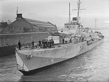
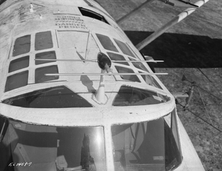
HMS Orchis was fitted with the first production 271, seen here atop the bridge.
At a meeting on 11 February 1941, the prototype order at Eastney was increased with another 12 units, and an order for 100 production sets was placed with Allen West and Company. At the same meeting, the newly completed Flower-class corvetteHMS Orchis was set aside for sea trials. The first batch of prototypes had been completed by the end of February 1941, which led to a follow-on order for another 150 sets.[16]
The system was rapidly fitted to Orchis and began trials in the Firth of Clyde on 25 March 1941. Mounted at the 36 foot (11m) mast height, the system could track a small submarine at 4,000 yards (3,700m) and saw some returns as far as 5,000 yards (4,600m). In higher sea-states, the maximum range was reduced to 4,400 yards (4,000m). While this was shorter than the ranges achieved with the experimental systems at Swanage, they were considered operationally useful, and were in any event much longer than visual range at night. Allen West was told to go ahead with the current design for production models.[17]
After the successful tests on Orchis, Eastney continued to produce the original order and increasingly liaised with Allen West on the production models. By September 1941, 32 corvettes had been equipped and a small number of other ships, including the battleship HMS King George V, cruiser HMS Kenya and naval trawlerAvalon. The system was not suitable for fitting to most destroyers or cruisers because it required the receiver room to be directly below the antenna, and most ships of that size had large masts taking up the suitable roof area.[12]
271, 272
During 1941, great strides were being made in microwave electronics and new solutions to problems were constantly being introduced. A number of such changes were worked into the production models as the prototype series came to an end.[12]
One such improvement was the CV35 reflex klystron which replaced the earlier NR89 of the 271X. The CV35 had an efficiency of 3 to 4%, compared to the original 1%, and therefore produced about three times the output signal for any given input. This allowed the distance between the antenna and receiver to be extended up to as much as 40 feet (12m), offering much more flexibility in mounting options. The CV35 was also electrically more stable and made tuning the system far easier.[12] Sets using the CV35 were initially known as 271X Mark II, but in March 1942 they were re-designated 271 Mark II, dropping the X.[18]
The original antenna arrangement was retained for the production 271s, but the mounting was changed to produce the Outfit ANB.[13] Further experiments were carried out that replaced the direct drive shaft that the operator used to turn the antennas with a Bowden cable to allow the cabin to be remote from the antenna. At the same time, those electronics that remained mounted on the antenna were repackaged to be as small as possible, reducing weight. With these changes, it was now possible to mount the antenna remotely, making it suitable for use on destroyers. In typical use, the antenna was mounted at the 55 foot (17m) level on the mast.[12] In August 1941, units with this sort of drive were renamed Type 272.[18]
The Type 272 was also mounted to cruisers, but in this role a new problem was discovered; the blast from the main guns was strong enough that it tended to crack the perspex in the radome. This was not wholly solved until 1943, when an entirely new radome was introduced.[18]
273
HMS Nigeria was the first ship to mount the operational Type 273, which can be seen on the mast above the dark rectangle of her Type 284.
The move to the cheese antenna resulted in a loss of performance, but one that was unavoidable due to the pitch and roll of the ships. Such was not the case on larger ships, where the slower movements in waves made it possible to offset the effects using a mechanical stabilizer. This led to experiments using the original 3 foot (0.91m) diameter parabolic mirrors used in the TRE sets for use on larger ships. These provided a gain of 250, far greater than the cheese antennas. Combined with the mounting higher on the mast, it was expected this system would offer significantly greater detection range. Six prototype systems were delivered in August 1941, given the name Type 273. The first production fitting was to HMS Nigeria at the end of the year.[19]
In October 1941, Mediterranean Command asked for some solution to the problem of detecting Italian human torpedoes which were attacking ships in Gibraltar and Alexandria. A modified version of the Type 273 was provided, removing the stabilization system (not needed on land) and further increasing the reflectors to 4.5 feet (1.4m) which improved gain to 575. Several such systems were built under the name Types 273S (for Shore) and delivered in 1942. A further one-off modification was made for the site at Saebol, Iceland, due to the high winds at that location. This Type 273M was mounted on a gun mount for extra stability. In testing on 29 September 1942, the 273M demonstrated a 92,000 yards (84,000m) range against a trawler from its 1,520 foot (460m) high location, which is only slightly short of the radar horizon of 96,000 yards (88,000m).[20]
P models
By the autumn of 1941 it was clear the demand for the new radars was far beyond their projected production rates. In addition to the demand for naval ships, the British Army was adopting them for Coast Defence radar purposes and the Air Ministry was interested in using them for short-range air traffic control and early warning. The initial order of 150 units with Allen West and Co was increased to 350.[20]
In order to speed production, Metropolitan-Vickers was contracted to redesign the electronics units to make them easier to manufacture. The original system consisted of three large cabinets in two vertical stacks. The new designs, which was given the model number "P", used only two cabinets mounted in a single vertical stack.[20]
To speed the fitting of the P models to ships, entirely new radar cabins were prefabricated for each ship that was expected to return from sea for its periodic boiler cleaning. The installation occurred in two stages: during one cleaning a new area on the ship was prepared for the radar, and on its next visit a completed unit was hoisted aboard by crane.[20]
PPI display
In 1941 the Air Ministry began work on the plan-position indicator, or PPI, a new type of radar display that produced a 2D image of the space around the radar station. The PPI is what one normally thinks of as a radar display, with a circular face and a visible beam rotating around it. This display was being used to help ease the task of plotting an airborne interception, as both the target aircraft and the interceptor appeared on the same display, allowing the operators to easily direct the interceptor.[21]
Late in 1941, the labs at Eastney began adapting the PPI for use with the Type 271. The display made scanning the surface dramatically easier as the operator could swing the antenna back and forth and the display would show the entire sweep as a single display. Previously they would have to carefully watch for "blips" in the display as they swung the antenna, and then rotate it back and forth in ever-smaller motions in order to determine the exact angle. Now they could make a single swing to develop an image of the entire area and measure the angle to targets off the face of the display.[21]
In February 1942 an experimental PPI using a 12 inches (300mm)cathode ray tube (CRT) display was fitted aboard the King George V. For this experiment, a motor was added to the flexible shaft that turned the antenna, which automatically rotated the antenna back and forth between its limits. The other end of the cable, formerly used by the operator to manually swing the antenna, was instead connected to a synchro that indicated the direction the antenna was currently facing. This was mixed with the signal from a Remote Indicating Compass. The resulting phase of the mixed output signal encoded the angle between the antenna and north, and was used to drive another synchro on the CRT's deflection plates. The result was a stabilized north-up display.[21]
In tests, the system immediately proved itself invaluable, and a contract was placed with EMI for what became known as "Outfit JE". The only difference between the prototype and the production models was the used of a smaller 9 inches (230mm) CRT which reduced the bulk of the resulting equipment cabin.[21]
New radome
HMS Hesperus tested the new frameless radome, seen here.
As the installation of 271 become more widespread in late 1941, operators began to note an odd problem where the reflection from larger ships in a convoy would cause large areas of the display to become unusable, creating a blip much larger than the ship and hiding objects near it. These were known as "side echoes," no hint of which had been seen during initial operations.[21]
Testing began in February 1942 using HMS Guillemot, a Kingfisher-class sloop, and later moved to the production model on the 271P on HMS Veteran in March. These quickly revealed the problem was due to the pillars that supported the roof of the lantern-style enclosure.[21] A new design entirely of perspex was developed, consisting of several thick cylinders that were stacked vertically to produce a complete radome.[15]
The first example was fitted to HMS Hesperus in November 1942, and the entire fleet had been modified by the end of 1943. The radome for the Type 273s took longer to design, as it was much heavier and also had to withstand the blast of the firing guns, but these were converted by the end of 1943.[15]
Q models
Development of microwave techniques continued at a rapid pace through 1941 and by the end of the year several significant improvements had progressed to production quality. Among these was the soft Sutton tube, which allowed a microwave signal to be switched between two wires, thereby allowing a single antenna to be used both for transmission and reception. Another improvement was the initial delivery of mass-produced semiconductor crystals from the United States, which were smaller and more robust than the UK models.[22]
The most surprising of all was the new "strapped" magnetron design, a seemingly minor modification that produced an enormous boost in performance, allowing a unit the same size of the original NT98 to reach efficiencies on the other of 40%, or even 50 to 60% when used with a new and more powerful magnet. This led to a corresponding boost in output, with no change to the power supply the radars could now produce as much as 500kW.[22]
The Navy had already tried to increase the performance of the existing sets by boosting the power of the NT98 magnetrons. They found that the NT98 could produce as much as 100kW of output using an input pulse of 1MW. However, this was at the very limit of the power-handling NT100 tetrodes. An intermediate goal was to produce a 25kW design, which was tested on the trailer at Eastney in September 1941. This was based on a new modulator that was triggered by a thyratron to produce the required power pulses.[23]
It was around the same time this new unit was being tested that the first strapped magnetron arrived in Eastney, the CV56. This was fitted to the experimental trailer and aimed at Nab Tower, their standard target. To everyone's surprise, the resulting signal was so powerful the only result was to melt the dipole in the transmitting antenna. This led to the adoption of a waveguide and feedhorn, which were being developed at the same time. Only a few weeks later an even more powerful magnetron arrived, the CV76, which produced 500kW.[24]
In order to deploy the new magnetrons as quickly as possible, it was decided to retain the existing antenna installations and use the CV56 at 70 to 100kW, ultimately settling at 70. Only the transmitter would be modified with a waveguide, the receiver would continue to use the coaxial feed. Three hand-built prototypes of the new equipment chassis were built at Eastney, along with an order for ten production prototypes each from Marconi and Allen West.[24] A new problem emerged; even though the system used separate transmitter and receiver antennas, the transmissions were so powerful that enough leaked signal reached the receiver's antenna to burn out the crystals. This required the addition of the soft Sutton tube to the receiver to further isolate it from the transmitter's signals.[25]
The first tests were carried out on HMS Marigold in May 1942 off Tobermory, which also tested its ability to see the splashes from the 4-inch naval gun shells. A second unit was fitted to the 273 antenna on King George and tested off Scapa Flow in July.[26] The second escort to receive 271Q was HMS Itchen, which was also the first to receive the new radome. This was especially important with the Q models as the increased power of the transmissions made the sidelobe reflections overwhelming.[25]
These test fits demonstrated another problem; targets at close range returned so much signal that it overwhelmed more distant targets, which made it difficult to track the U-boats while near a convoy. This problem was ultimately solved by the introduction of a swept-gain system that muted down the signals from close-in objects. These arrived in late 1943.[26]
Q models in action
HMS Duke of York returns from her battle with Scharnhorst. The 273Q can be seen near the top of the mast.
According to the radar equation, the detection performance of a radar varies with the fourth root of transmitted power,[27] so even with the new system delivering about 45 times the output, effective range increased by about 2.6 times. This still represented a significant improvement, as it allowed U-boats to be detected to the radar horizon from the escorts, beyond which detection would be impossible anyway. A more important difference was that the signals that were returned from shorter ranges were stronger, making them much more stable on the displays.[28]
The system's most famous action was during the Battle of the North Cape on 26 December 1943, when the 273Q on HMS Duke of York detected the German battleship Scharnhorst at a range of 45,500 yards (41.6km), and tracked her continually from that point onward.[29] Beginning at 17.5 nautical miles (32.4km; 20.1mi) Type 284 acquired the target and Type 281 beginning at 12.75 nautical miles (23.61km; 14.67mi).[30] This early detection, combined with accurate blind-fire ranging from the Type 284 radar, led to the Duke of York landing her very first salvo on Scharnhorst and putting her forward batteries out of action.[31]Scharnhorst was unaware of Duke of York because her own Seetakt radar had been damaged. Hits from Duke of York's 14-inch guns slowed her until the British and Norwegian destroyers were able to close and finish her off with torpedoes.[32]
Duke of York's 273 was briefly knocked out when two shells from Scharnhorst flew through the mast area. This made the stabilized platform guiding the 273's antenna lose its orientation and the antennas ended up pointing into the air. Lieutenant Bates, commander in the radar cabin, climbed the mast and managed to reorient the antenna successfully. From that moment on he was known as "Barehand Bates".[33]
The Commander-in-Chief Home Fleet praised the performance of the system:
a) The surface warning provided by Type 273Q was entirely satisfactory, giving on PPI a clear picture of the situation throughout the engagement. Blast from the ship's own broadsides so shook the office that some of the overhead supports for the panels were carried away, but the set remained functioning throughout the entire period.
b) Gyro-stabilisation of the aerial proved its worth, justifying for the first time the fitting of such gear in capital ships.
c) The successful presentation on the PPI of the tactical situation was almost entirely due to the improved performance of the set since fitting the cylindrical perspex lantern; this, by cutting down side-echoes to negligible proportions, has improved the value of the set by one hundred percent.
d) The picking-up range of Scharnhorst was 45,500 yards, nearly the full visual range of Scharnhorst's director tower from the height of the Duke of York's radar aerial.
e) Type 281 was able to hold the Scharnhorst up to 12.75 nautical miles, a reminder of the useful part this set can play as a stand-by for surface warning.[29]
The performance against submarines was not quite so apparent, as their low profiles allowed them to disappear behind large waves. However, post-war analysis demonstrated that the 271Q offered a significant improvement in terms of sightings. From 1943, when the radar first became common, the first sighting range increased from an average of 3 to 5 miles (4.8 to 8.0km), an increase of more than 50%.[34]
Further development of the 271 series using the CV76 magnetron and numerous other improvements was originally carried out under the Mark V name. The main improvement was the 500kW magnetrons and the single transmit/receive antenna. Over time these changes were considered so significant that they were given their own names, becoming the Type 277 radar and the associated 276 and 293. These versions began to replace the 271s starting in mid-1944, and had completely replaced them for new installations by 1945.[35]
Ships continued to receive the 271Q through the transition period, including, for example, HMCS Haida, which received her 271Q in 1944. These late-war installations tended to be replaced for those ships that survived into the post-war era; Haida received a Type 293 in 1946.[36]
Other uses
The Type 271 was so ahead of its time that it found a number of uses in unrelated roles where it served out the war in front-line service.[37]
Coast Defence
A significant role for the 271 was the British Army's adaptation to the Coastal Defence role. These radars were placed along the eastern coast of the British Isles to look for enemy ships in the English Channel. Earlier units based on 1.5m wavelength VHF systems had troubles finding E-boats, a problem the 271's shorter wavelength and much higher resolution eliminated.[38]
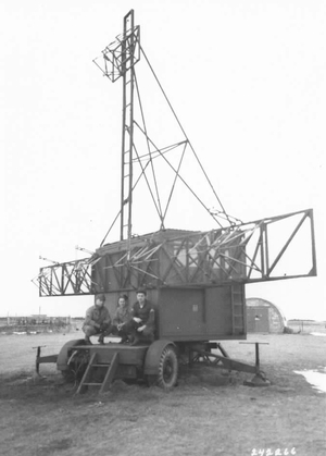
Very early in development, one of the 271X units was sent to the Army's radar research site, ADRDE in Christchurch, Dorset. As was the case for the 273, the fan-shaped beam of the cheese antenna was not needed and it was replaced by a parabolic reflector. These were even larger than the original three foot designs of the test models, increasing to 7 feet (2.1m) diameter. These improved gain about 25 times compared to the 271 and about five times that of the 273.[38]
The entire system, including the operator's cabin, was mounted on an anti-aircraft gun carriage. The antennas were mounted directly to the side of the cabin, rotating with it. This had the significant advantage that the coaxial cables between the antennas and the equipment inside were very short. The first example was sited at the Lydden Spout Battery in July 1941. Unofficially referred to as Type NT271X, it was later given the official name Radar, Coast Defence, Number 1 Mark 4, or CD No.1 Mk.4 for short.[38]
By the end of August, the testing team reported:
Operationally NT271X was a great advance on previous sets in maximum range, discrimination, counting and accuracy. For the first time reliable cover was obtained across the Channel, so that not even E-boats could go between Calais and Boulogne undetected. Large ships could be watched at anchor in the outer harbour of Boulogne.[38]
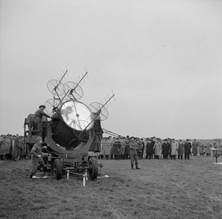
The tests were so successful that the prototype was left in-place as an operational unit, and immediate order for another twelve hand-built units was placed with ADRDE. A further order for fifty production models mounted on a mobile trailer was placed, and formed the "K" stations of the coast defence network.[38]
As the 271 continued to be modified with new equipment and techniques, the Army followed suit. The use of the soft Sutton tube allowed the second antenna to be removed, and the addition of waveguides improved the packaging possibilities. A new version, Radar, Coast Defence, Number 1 Mark 5, mounted the now single antenna on a separate and much smaller trailer with the rest of the electronics in a non-rotating semi-trailer. Some were mounted on permanent mounts, in which case they were known as Radar, Coast Defence, Number 1 Mark 6.[38]
Chain Home Extra Low
As the Army began deploying the CD Mk.4 radars, the Royal Air Force (RAF) began noticing new attacks by German aircraft that were not being detected by their Chain Home Low systems. These raids, later nicknamed "tip-n-run" after a backyard cricket rule, used high-speed fighter bombers like the Focke-Wulf Fw 190. The aircraft flew at extremely low altitudes, perhaps 100 feet (30m) over the water, bombed a sea-side target, and then quickly turned for home. The aircraft were visible to radar only for the few moments when they climbed above their targets and then turned away.[39]
To address these attacks, in December 1942 the RAF took over eleven of the CD units and renamed them the AMES Type 52, but much better known as Chain Home Extra Low. A further three were added to the network in May 1943. These followed the same development as the Army models, and over time were known as the Type 52 through Type 56.[39] In total, 38 stations were eventually added to the network.
Description
Antenna layout
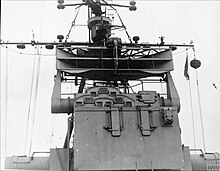
The "double cheese" antenna of the 271 was similar to this Type 274 antenna seen on HMS Swiftsure.
The 271 required a thin beam side-to-side in order to provide accuracy while having a wide beam up-and-down so that the signal hit the water's surface as the ship pitched and rolled. This led to the use of a "cheese" antenna design, which consists of a slice cut out of a parabolic reflector with plates on the top and bottom. The resulting design "squeezes" the signal between the two plates, and it rapidly spreads out as it exits the area between them. Additionally, production models of the antenna clipped the outer edges of the parabolic section to make the antenna narrower.[12] The clipped portions were fitted with small end-plates, which gave rise to the side-reflections.[25]
The 271 was designed just before the development of a system for switching an antenna between a transmitter and receiver working at microwave frequencies, so two separate antennas were used, placed one on top of the other. The flat upper and lower surfaces of the cheese made this simple, and the metal plates protected the receiver from stray signals from the transmitter.[25]
The antenna was mounted on a post running through a metal tube. The top of the tube held a bearing system that the antenna sat on. The post ran through the roof of the radar operator's cabin and ended in a large wheel that was used to manually turn the antenna.[25]
The standard Outfit ANB had a gain of approximately 55. The 273's larger 3 foot (0.91m) reflector improved this to about 250 while the 273S land-based model's 4.5 foot (1.4m) reflector further improved this to 575.[40]
Electronics
The 271's electronics were state-of-the-art for the 1940s, and give some indication of the difficulty in producing such systems at the time. The receiver in the original 271X had 20dB of noise, but this improved slightly in production to 16 - 18dB. The introduction of US-made detector crystals offered a further improvement to 14 - 16dB.[40]
In early fits, the equipment was packed into two large cabinets, about as tall as a common refrigerator but somewhat narrower.[41] For production units, this had been reduced to a single cabinet with two large boxes on the bottom and middle, and a much smaller unit on top. The lowest unit was the power supply and pulse-forming system, with the receiver and display on the middle, and tuner on top.[42]
The P-models added the PPI display, which was otherwise similar to the later production models of the earlier marks.[42] The Q-models deliberately used the same layout as the P in order to ease conversion.[43]
Displays and interpretation
Early models, A through M, used an A-scan display. This used a single cathode ray tube (CRT) with the beam being pulled across the display left-to-right by a time base generator triggered by the transmission pulses. Targets along the current line of sight, or "line of shoot" as it is known in radar terms, caused the beam to deflect slightly, forming a "blip" on the display. Since the motion of the beam was timed to be the same as the time of the radar signal, the position across the face of the CRT was a direct analog of the range to the target. The system had two range settings, 5,000 yards (4.6km) and 15,000 yards (14km). The CRT could also be used to measure the pulse shapes and perform other maintenance duties.[41]
The P and Q models changed the display to be, primarily, a plan-position indicator using a larger 9 inches (230mm) CRT. On this display the antenna's angle relative to magnetic north is used to rotate the beam around the display face, with "north up". A time base is used to pull the beam from the center to the outer rim along this angle. Instead of deflecting the beam to produce a blip, the amplified signal instead causes the signal to grow brighter. When the antenna sweeps by a target, a small blip lights up on the otherwise dark display face. Getting this to work requires careful adjustment by the operator to mute down the internal noise of the amplifier without also muting out small signals.[42]
Related Research Articles
Radar is a radiolocation system that uses radio waves to determine the distance (ranging), angle (azimuth), and radial velocity of objects relative to the site. It is used to detect and track aircraft, ships, spacecraft, guided missiles, motor vehicles, map weather formations, and terrain. A radar system consists of a transmitter producing electromagnetic waves in the radio or microwaves domain, a transmitting antenna, a receiving antenna and a receiver and processor to determine properties of the objects. Radio waves from the transmitter reflect off the objects and return to the receiver, giving information about the objects' locations and speeds.
H2S was the first airborne, ground scanning radar system. It was developed for the Royal Air Force's Bomber Command during World War II to identify targets on the ground for night and all-weather bombing. This allowed attacks outside the range of the various radio navigation aids like Gee or Oboe, which were limited to about 350 kilometres (220 mi) of range from various base stations. It was also widely used as a general navigation system, allowing landmarks to be identified at long range.
The Naxos radar warning receiver was a World War II German countermeasure to S band microwave radar produced by a cavity magnetron. Introduced in September 1943, it replaced Metox, which was incapable of detecting centimetric radar. Two versions were widely used, the FuG 350 Naxos Z that allowed night fighters to home in on H2S radars carried by RAF Bomber Command aircraft, and the FuMB 7 Naxos U for U-boats, offering early warning of the approach of RAF Coastal Command patrol aircraft equipped with ASV Mark III radar. A later model, Naxos ZR, provided warning of the approach of RAF night fighters equipped with AI Mk. VIII radar.
The history of radar started with experiments by Heinrich Hertz in the late 19th century that showed that radio waves were reflected by metallic objects. This possibility was suggested in James Clerk Maxwell's seminal work on electromagnetism. However, it was not until the early 20th century that systems able to use these principles were becoming widely available, and it was German inventor Christian Hülsmeyer who first used them to build a simple ship detection device intended to help avoid collisions in fog. True radar, such as the British Chain Home early warning system provided directional information to objects over short ranges, were developed over the next two decades.
Serrate was a World War II Allied radar detection and homing device used by night fighters to track Luftwaffe night fighters equipped with the earlier UHF-band BC and C-1 versions of the Lichtenstein radar. It allowed RAF night fighters to attack their German counterparts, disrupting their attempts to attack the RAF's bomber force.
Radar in World War II greatly influenced many important aspects of the conflict. This revolutionary new technology of radio-based detection and tracking was used by both the Allies and Axis powers in World War II, which had evolved independently in a number of nations during the mid 1930s. At the outbreak of war in September 1939, both the United Kingdom and Germany had functioning radar systems. In the UK, it was called RDF, Range and Direction Finding, while in Germany the name Funkmeß (radio-measuring) was used, with apparatuses called Funkmessgerät . By the time of the Battle of Britain in mid-1940, the Royal Air Force (RAF) had fully integrated RDF as part of the national air defence.
The AN/FPS-6 Radar was a long-range height finding radar used by the United States Air Force's Air Defense Command. The AN/FPS-6 radar was introduced into service in the late 1950s and served as the principal height-finder radar for the United States for several decades thereafter. It was also used by the Royal Air Force alongside their AMES Type 80s. Built by General Electric, the S-band radar operated on a frequency of 2700 to 2900 MHz. Between 1953 and 1960, about 450 units of the AN/FPS-6 and the mobile AN/MPS-14 version were produced. The AN/FPS-90 and AN/FPS-116 radars were identical to the AN/FPS-6 except for receiver modifications.
Radar, Airborne Interception, Mark IV, produced by USA as SCR-540, was the world's first operational air-to-air radar system. Early Mk. III units appeared in July 1940 on converted Bristol Blenheim light bombers, while the definitive Mk. IV reached widespread availability on the Bristol Beaufighter heavy fighter by early 1941. On the Beaufighter, the Mk. IV arguably played a role in ending the Blitz, the Luftwaffe's night bombing campaign of late 1940 and early 1941.
Radar, Airborne Interception, Mark VIII, or AI Mk. VIII for short, was the first operational microwave-frequency air-to-air radar. It was used by Royal Air Force night fighters from late 1941 until the end of World War II. The basic concept, using a moving parabolic antenna to search for targets and track them accurately, remained in use by most airborne radars well into the 1980s.
Airborne Interception radar, or AI for short, is the British term for radar systems used to equip aircraft in air-to-air role. These radars are used primarily by Royal Air Force (RAF) and Fleet Air Arm night fighters and interceptors for locating and tracking other aircraft, although most AI radars could also be used in a number of secondary roles as well. The term was sometimes used generically for similar radars used in other countries.
Radar, Gun Laying, Mark I, or GL Mk. I for short, was an early radar system developed by the British Army to provide range information to associated anti-aircraft artillery. There were two upgrades to the same basic system, GL/EF and GL Mk. II, both of which added the ability to accurately determine bearing and elevation.
Radar, Gun Laying, Mark III, or GL Mk. III for short, was a radar system used by the British Army to directly guide, or lay, anti-aircraft artillery (AA). The GL Mk. III was not a single radar, but a family of related designs that saw constant improvement during and after World War II. These were renamed shortly after their introduction in late 1942, becoming the Radar, AA, No. 3, and often paired with an early warning radar, the AA No. 4, which was also produced in several models.
The Type 277 was a surface search and secondary aircraft early warning radar used by the Royal Navy and allies during World War II and the post-war era. It was a major update of the earlier Type 271 radar, offering much more power, better signal processing, new displays, and new antennas with greatly improved performance and much simpler mounting requirements. It allowed a radar with performance formerly found only on cruisers and battleships to be fitted even to the smallest corvettes. It began to replace the 271 in 1943 and was widespread by the end of the year.
Searchlight Control, SLC for short but nicknamed "Elsie", was a British Army VHF-band radar system that provided aiming guidance to an attached searchlight. By combining a searchlight with a radar, the radar did not have to be particularly accurate, it only had to be good enough to get the searchlight beam on the target. Once the target was lit, normal optical instruments could be used to guide the associated anti-aircraft artillery. This allowed the radar to be much smaller, simpler and less expensive than a system with enough accuracy to directly aim the guns, like the large and complex GL Mk. II radar. In 1943 the system was officially designated Radar, AA, No. 2, although this name is rarely used.
The AMES Type 82, also widely known by its rainbow codename Orange Yeoman, was an S-band 3D radar built by the Marconi Company and used by the Royal Air Force (RAF), initially for tactical control and later for air traffic control (ATC).
Radar, Air-to-Surface Vessel, Mark II, or ASV Mk. II for short, was an airborne sea-surface search radar developed by the UK's Air Ministry immediately prior to the start of World War II. It was the first aircraft mounted radar of any sort to be used operationally. It was widely used by aircraft of the RAF Coastal Command, Fleet Air Arm and similar groups in the United States and Canada. A version was also developed for small ships, the Royal Navy's Type 286.
Radar, Air-to-Surface Vessel, Mark III, or ASV Mk. III for short, was a surface search radar system used by RAF Coastal Command during World War II. It was a slightly modified version of the H2S radar used by RAF Bomber Command, with minor changes to the antenna to make it more useful for the anti-submarine role. It was Coastal Command's primary radar from the spring of 1943 until the end of the war. Several improved versions were introduced, notably the ASV Mark VI, which replaced most Mk. IIIs from 1944 and ASV Mark VII radar, which saw only limited use until the post-war era.
The British Army's Wireless Set, Number 10, was the world's first microwave relay telephone system. It transmitted eight full-duplex (two-way) telephone channels between two stations limited only by the line-of-sight, often on the order of 25 to 50 miles. The stations were mounted in highly mobile trailers and were set up simply by aiming the two parabolic antennas on the roof at the next station.
SW1C, short for Surface Warning, Model 1, Canadian, was an early radar system developed by the National Research Council of Canada (NRC) for the Royal Canadian Navy (RCN).
This page is based on this Wikipedia article Text is available under the CC BY-SA 4.0 license; additional terms may apply. Images, videos and audio are available under their respective licenses.