Related Research Articles
For many cameras, depth of field (DOF) is the distance between the nearest and the farthest objects that are in acceptably sharp focus in an image. The depth of field can be calculated based on focal length, distance to subject, the acceptable circle of confusion size, and aperture. A particular depth of field may be chosen for technical or artistic purposes. Limitations of depth of field can sometimes be overcome with various techniques and equipment.
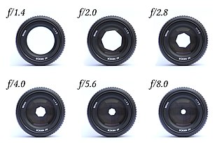
In optics, an aperture is a hole or an opening through which light travels. More specifically, the aperture and focal length of an optical system determine the cone angle of a bundle of rays that come to a focus in the image plane.

In optics, a circle of confusion is an optical spot caused by a cone of light rays from a lens not coming to a perfect focus when imaging a point source. It is also known as disk of confusion, circle of indistinctness, blur circle, or blur spot.

Photonics is the physical science and application of light (photon) generation, detection, and manipulation through emission, transmission, modulation, signal processing, switching, amplification, and sensing. Though covering all light's technical applications over the whole spectrum, most photonic applications are in the range of visible and near-infrared light. The term photonics developed as an outgrowth of the first practical semiconductor light emitters invented in the early 1960s and optical fibers developed in the 1970s.

Adaptive optics (AO) is a technology used to improve the performance of optical systems by reducing the effect of incoming wavefront distortions by deforming a mirror in order to compensate for the distortion. It is used in astronomical telescopes and laser communication systems to remove the effects of atmospheric distortion, in microscopy, optical fabrication and in retinal imaging systems to reduce optical aberrations. Adaptive optics works by measuring the distortions in a wavefront and compensating for them with a device that corrects those errors such as a deformable mirror or a liquid crystal array.

Computational photography refers to digital image capture and processing techniques that use digital computation instead of optical processes. Computational photography can improve the capabilities of a camera, or introduce features that were not possible at all with film based photography, or reduce the cost or size of camera elements. Examples of computational photography include in-camera computation of digital panoramas, high-dynamic-range images, and light field cameras. Light field cameras use novel optical elements to capture three dimensional scene information which can then be used to produce 3D images, enhanced depth-of-field, and selective de-focusing. Enhanced depth-of-field reduces the need for mechanical focusing systems. All of these features use computational imaging techniques.

A catadioptric optical system is one where refraction and reflection are combined in an optical system, usually via lenses (dioptrics) and curved mirrors (catoptrics). Catadioptric combinations are used in focusing systems such as searchlights, headlamps, early lighthouse focusing systems, optical telescopes, microscopes, and telephoto lenses. Other optical systems that use lenses and mirrors are also referred to as "catadioptric", such as surveillance catadioptric sensors.
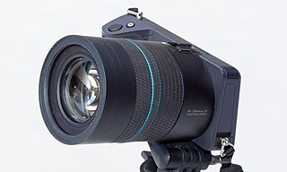
A light field camera, also known as a plenoptic camera, is a camera that captures information about the light field emanating from a scene; that is, the intensity of light in a scene, and also the precise direction that the light rays are traveling in space. This contrasts with conventional cameras, which record only light intensity.

The optical transfer function (OTF) of an optical system such as a camera, microscope, human eye, or projector specifies how different spatial frequencies are handled by the system. It is used by optical engineers to describe how the optics project light from the object or scene onto a photographic film, detector array, retina, screen, or simply the next item in the optical transmission chain. A variant, the modulation transfer function (MTF), neglects phase effects, but is equivalent to the OTF in many situations.

In optics, defocus is the aberration in which an image is simply out of focus. This aberration is familiar to anyone who has used a camera, videocamera, microscope, telescope, or binoculars. Optically, defocus refers to a translation of the focus along the optical axis away from the detection surface. In general, defocus reduces the sharpness and contrast of the image. What should be sharp, high-contrast edges in a scene become gradual transitions. Fine detail in the scene is blurred or even becomes invisible. Nearly all image-forming optical devices incorporate some form of focus adjustment to minimize defocus and maximize image quality.
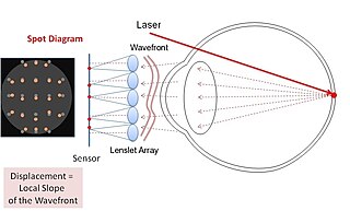
A Shack–Hartmannwavefront sensor (SHWFS) is an optical instrument used for characterizing an imaging system. It is a wavefront sensor commonly used in adaptive optics systems. It consists of an array of lenses of the same focal length. Each is focused onto a photon sensor. If the sensor is placed at the geometric focal plane of the lenslet, and is uniformly illuminated, then, the integrated gradient of the wavefront across the lenslet is proportional to the displacement of the centroid. Consequently, any phase aberration can be approximated by a set of discrete tilts. By sampling the wavefront with an array of lenslets, all of these local tilts can be measured and the whole wavefront reconstructed. Since only tilts are measured the Shack–Hartmann cannot detect discontinuous steps in the wavefront.
Digital holography refers to the acquisition and processing of holograms with a digital sensor array, typically a CCD camera or a similar device. Image rendering, or reconstruction of object data is performed numerically from digitized interferograms. Digital holography offers a means of measuring optical phase data and typically delivers three-dimensional surface or optical thickness images. Several recording and processing schemes have been developed to assess optical wave characteristics such as amplitude, phase, and polarization state, which make digital holography a very powerful method for metrology applications .

Coded apertures or coded-aperture masks are grids, gratings, or other patterns of materials opaque to various wavelengths of electromagnetic radiation. The wavelengths are usually high-energy radiation such as X-rays and gamma rays. By blocking radiation in a known pattern, a coded "shadow" is cast upon a plane. The properties of the original radiation sources can then be mathematically reconstructed from this shadow. Coded apertures are used in X- and gamma ray imaging systems, because these high-energy rays cannot be focused with lenses or mirrors that work for visible light.
Computer-generated holography (CGH) is the method of digitally generating holographic interference patterns. A holographic image can be generated e.g. by digitally computing a holographic interference pattern and printing it onto a mask or film for subsequent illumination by suitable coherent light source.
Boston Micromachines Corporation is a US company operating out of Cambridge, Massachusetts. Boston Micromachines manufactures and develops instruments based on MEMS technology to perform open and closed-loop adaptive optics. The technology is applied in astronomy, beam shaping, vision science, retinal imaging, microscopy, laser communications, and national defense. The instruments developed at Boston Micromachines include deformable mirrors, optical modulators, and retinal imaging systems, all of which utilize adaptive optics technology to enable wavefront manipulation capabilities which enhance the quality of the final image.
A flat lens is a lens whose flat shape allows it to provide distortion-free imaging, potentially with arbitrarily-large apertures. The term is also used to refer to other lenses that provide a negative index of refraction. Flat lenses require a refractive index close to −1 over a broad angular range. In recent years, flat lenses based on metasurfaces were also demonstrated.
ALPAO is a company which manufactures a range of adaptive optics products for use in research and industry, including deformable mirrors with large strokes, wavefront sensors, and adaptive optics loops. These products are designed for astronomy, vision science, microscopy, wireless optical communications, and laser applications.
Computational imaging is the process of indirectly forming images from measurements using algorithms that rely on a significant amount of computing. In contrast to traditional imaging, computational imaging systems involve a tight integration of the sensing system and the computation in order to form the images of interest. The ubiquitous availability of fast computing platforms, the advances in algorithms and modern sensing hardware is resulting in imaging systems with significantly enhanced capabilities. Computational Imaging systems cover a broad range of applications include computational microscopy, tomographic imaging, MRI, ultrasound imaging, computational photography, Synthetic Aperture Radar (SAR), seismic imaging etc. The integration of the sensing and the computation in computational imaging systems allows for accessing information which was otherwise not possible. For example:
A pyramid wavefront sensor is a type of a wavefront sensor. It measures the optical aberrations of an optical wavefront. This wavefront sensor uses a pyramidal prism with a large apex angle to split the beam into multiple parts at the geometric focus of a lens. A four-faceted prism, with its tip centered at the peak of the point spread function, will generate four identical pupil images in the absence of optical aberrations. In the presence of optical aberrations, the intensity distribution among the pupils will change. The local wavefront gradients can be obtained by recording the distribution of intensity in the pupil images. The wavefront aberrations can be evaluated from the estimated wavefront gradients.
The time-domain counterpart of spatial holography is called "Time-Domain Holography". In other words, the principles of spatial holography is surveyed in time domain. Time-domain holography was inspired by the theory known as "Space-Time Duality" which was introduced by Brian H. Kolner in 1994.