
Radar is a system that uses radio waves to determine the distance (ranging), direction, and radial velocity of objects relative to the site. It is a radiodetermination method used to detect and track aircraft, ships, spacecraft, guided missiles, motor vehicles, map weather formations, and terrain.
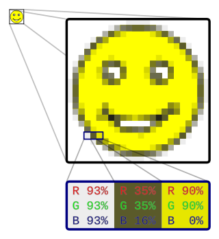
In computer graphics and digital photography, a raster graphic represents a two-dimensional picture as a rectangular matrix or grid of pixels, viewable via a computer display, paper, or other display medium. A raster image is technically characterized by the width and height of the image in pixels and by the number of bits per pixel. Raster images are stored in image files with varying dissemination, production, generation, and acquisition formats.

In a raster scan display, the vertical blanking interval (VBI), also known as the vertical interval or VBLANK, is the time between the end of the final visible line of a frame or field and the beginning of the first visible line of the next frame or field. It is present in analog television, VGA, DVI and other signals. Here the term field is used in interlaced video, and the term frame is used in progressive video and there can be a VBI after each frame or field. In interlaced video a frame is made up of 2 fields. Sometimes in interlaced video a field is called a frame which can lead to confusion.

Weather radar, also called weather surveillance radar (WSR) and Doppler weather radar, is a type of radar used to locate precipitation, calculate its motion, and estimate its type. Modern weather radars are mostly pulse-Doppler radars, capable of detecting the motion of rain droplets in addition to the intensity of the precipitation. Both types of data can be analyzed to determine the structure of storms and their potential to cause severe weather.
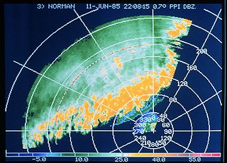
A plan position indicator (PPI) is a type of radar display that represents the radar antenna in the center of the display, with the distance from it and height above ground drawn as concentric circles. As the radar antenna rotates, a radial trace on the PPI sweeps in unison with it about the center point. It is the most common type of radar display.
A second mate or second officer (2/O) is a licensed member of the deck department of a merchant ship holding a Second Mates Certificate of Competence, by an authorised governing state of the International Maritime Organization (IMO). The second mate is the third in command and a watchkeeping officer, customarily the ship's navigator. Other duties vary, but the second mate is often the medical officer and in charge of maintaining distress signaling equipment. On oil tankers, the second mate usually assists the chief mate with the cargo operations.
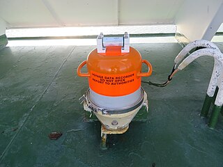
A voyage data recorder, or VDR, is a data recording system designed for all vessels required to comply with the IMO's International Convention SOLAS Requirements in order to collect data from various sensors on board the vessel. It then digitizes, compresses and stores this information in an externally mounted protective storage unit. The protective storage unit is a tamper-proof unit designed to withstand the extreme shock, impact, pressure and heat, which could be associated with a marine incident.

A raster scan, or raster scanning, is the rectangular pattern of image capture and reconstruction in television. By analogy, the term is used for raster graphics, the pattern of image storage and transmission used in most computer bitmap image systems. The word raster comes from the Latin word rastrum, which is derived from radere ; see also rastrum, an instrument for drawing musical staff lines. The pattern left by the lines of a rake, when drawn straight, resembles the parallel lines of a raster: this line-by-line scanning is what creates a raster. It is a systematic process of covering the area progressively, one line at a time. Although often a great deal faster, it is similar in the most general sense to how one's gaze travels when one reads lines of text.

High Angle Control System (HACS) was a British anti-aircraft fire-control system employed by the Royal Navy from 1931 and used widely during World War II. HACS calculated the necessary deflection required to place an explosive shell in the location of a target flying at a known height, bearing and speed.
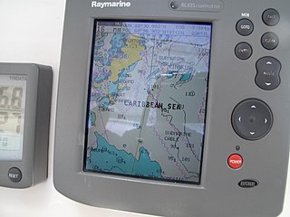
A chartplotter is a device used in marine navigation that integrates GPS data with an electronic navigational chart (ENC).

A radar display is an electronic device that presents radar data to the operator. The radar system transmits pulses or continuous waves of electromagnetic radiation, a small portion of which backscatter off targets and return to the radar system. The receiver converts all received electromagnetic radiation into a continuous electronic analog signal of varying voltage that can be converted then to a screen display.

A vector monitor, vector display, or calligraphic display is a display device used for computer graphics up through the 1970s. It is a type of CRT, similar to that of an early oscilloscope. In a vector display, the image is composed of drawn lines rather than a grid of glowing pixels as in raster graphics. The electron beam follows an arbitrary path, tracing the connected sloped lines rather than following the same horizontal raster path for all images. The beam skips over dark areas of the image without visiting their points.
Radar geo-warping is the adjustment of geo-referenced radar images and video data to be consistent with a geographical projection. This image warping avoids any restrictions when displaying it together with video from multiple radar sources or with other geographical data including scanned maps and satellite images which may be provided in a particular projection. There are many areas where geo warping has unique benefits:
Mini-automatic radar plotting aid is a maritime radar feature for target tracking and collision avoidance. Targets must be manually selected, but are then tracked automatically, including range, bearing, target speed, target direction (course), CPA, and TCPA, safe or dangerous indication, and proximity alarm. MARPA is a more basic form of ARPA.

The Low Flying Detection Radar also called Indian Doppler Radar (INDRA) series of 2D radars were developed by Electronics and Radar Development Establishment (LRDE), of the Defence Research and Development Organisation (DRDO) for the Army and the Air Force. These were then produced by the Bharat Electronics which generally the production partner of LRDE. The INDRA-I is a mobile surveillance radar for low level target detection while the INDRA-II is for ground controlled interception of targets.

Marine radars are X band or S band radars on ships, used to detect other ships and land hazards, to provide bearing and distance for collision avoidance and navigation at sea. They are electronic navigation instruments that use a rotating antenna to sweep a narrow beam of microwaves around the water surface surrounding the ship to the horizon, detecting targets by microwaves reflected from them, generating a picture of the ship's surroundings on a display screen. The X-Band and S-Band radar has different characteristics and detection capabilities compared with each other. Most merchant ships carry at least one of each type to ensure adequate target detection and response. For example, the S-band operates better in sea clutter and rain than the X-band, however, the X-band has greater definition and accuracy in clear weather.
A track algorithm is a radar and sonar performance enhancement strategy. Tracking algorithms provide the ability to predict future position of multiple moving objects based on the history of the individual positions being reported by sensor systems. Historical information is accumulated and used to predict future position for use with air traffic control, threat estimation, combat system doctrine, gun aiming, missile guidance, and torpedo delivery. Position data is accumulated over the span of a few minutes to a few weeks.
A time base generator is a special type of function generator, an electronic circuit that generates a varying voltage to produce a particular waveform. Time base generators produce very high frequency sawtooth waves specifically designed to deflect the beam of a cathode ray tube (CRT) smoothly across the face of the tube and then return it to its starting position.
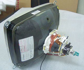
A deflection yoke is a kind of magnetic lens, used in cathode ray tubes to scan the electron beam both vertically and horizontally over the whole screen.
