Artificial lift

Last updated

Artificial lift refers to the use of artificial means to increase the flow of liquids, such as crude oil or water, from a production well. Generally this is achieved by the use of a mechanical device inside the well (known as pump or velocity string) or by decreasing the weight of the hydrostatic column by injecting gas into the liquid some distance down the well. A newer method called Continuous Belt Transportation (CBT) uses an oil absorbing belt to extract from marginal and idle wells. Artificial lift is needed in wells when there is insufficient pressure in the reservoir to lift the produced fluids to the surface, but often used in naturally flowing wells (which do not technically need it) to increase the flow rate above what would flow naturally. The produced fluid can be oil, water or a mix of oil and water, typically mixed with some amount of gas.

Contents

Usage

Any liquid-producing reservoir will have a 'reservoir pressure': some level of energy or potential that will force fluid (liquid, gas or both) to areas of lower energy or potential. The concept is similar to that of water pressure in a municipal water system. As soon as the pressure inside a production well is decreased below the reservoir pressure, the reservoir will act to fill the well back up, just like opening a valve on a water system. Depending on the depth of the reservoir and density of the fluid, the reservoir may or may not have enough potential to push the fluid to the surface - a deeper well or a heavier mixture results in a higher pressure requirement.

Technologies

Hydraulic pumping systems

Hydraulic pumping systems transmit energy to the bottom of the well by means of pressurized power fluid that flows down in the wellbore tubular to a subsurface pump. There are at least three types of hydraulic subsurface pump:

  1. a reciprocating piston pump, where one side is powered by the (injected) drive fluid while the other side pumps the produced fluids to surface
  2. a jet pump, where the (injected) drive fluid passes through a nozzle-throat venturi combination, mixes with produced fluids and by the venturi effect creates a high pressure at the discharge side of the pump.
  3. a hydraulically driven downhole turbine (HSP), whereby the downhole drive motor is a turbine, mechanically connected to the impeller-pump section which pumps the fluid.

These systems are very versatile and have been used in shallow depths (1,000 ft) to deeper wells (18,000 ft), low rate wells with production in the tens of barrels per day to wells producing in excess of 20,000 bbl (3,200 m3) per day. In most cases the drive (injected) fluid can be water or produced fluids (oil/water mix). Certain chemicals can be mixed in with the injected fluid to help control corrosion, paraffin and emulsion problems. Hydraulic pumping systems are also suitable for deviated wells where conventional pumps such as the rod pump are not feasible.

Like all systems, these systems have their operating envelopes, though with hydraulic pumps these are often misunderstood by designers. Some types of hydraulic pumps may be sensitive to solids, while jetpumps for example can pump solids volume fractions of more than 50%. They are considered the least efficient lift method, though this differs for the different types of hydraulic pumps, and also when looking at full system losses the differences in many installations are negligible.

The life-cycle cost of these systems is similar to other types of artificial lift when appropriately designed, bearing in mind that they are typically low maintenance, with jet pumps for instance having slightly higher operating (energy) costs with substantially lower purchase cost and virtually no repair cost.

ESP

Electric Submersible Pumps (ESP) consist of a downhole pump (a series of centrifugal pumps), an electrical motor which transforms the electrical power into kinetic energy to turn the pump, a separator or protector to prevent produced fluids from entering the electrical motor, and an electric power cable that connects the motor to the surface control panel. ESP is a very versatile artificial lift method and can be found in operating environments all over the world. They can handle a very wide range of flow rates (from 200 to 90,000 barrels (14,000 m3) per day) and lift requirements (from virtually zero to 10,000 ft (3,000 m) of lift). They can be modified to handle contaminants commonly found in oil, aggressive corrosive fluids such as H2S and CO2, and exceptionally high downhole temperatures. Increasing water cut has been shown to have no significant detrimental effect on the ESP performance. It is possible to locate them in vertical, deviated, or horizontal wells, but it is recommended to deploy them in a straight section of casing for optimum run life performance.

Although latest developments are aimed to enhance the ESP capabilities to handle gas and sand, they still need more technological development to avoid gas locks and internal erosion. Until recently, ESPs have come with an often prohibitive price tag due to the cost of deployment which can be in excess of $20,000.

Various tools such as Automatic Diverter Valves (ADV), SandCats and other Tubing String and Pump Tools enhance the performance of the ESP. The majority of systems deployed in today's market are Dual ESP Systems which is a simple arrangement of two ESPs in the same well. This delivers a complete downhole system booster or back up - downtime is minimal, workovers cost less and there are savings in other operational areas. ESP Dual Systems bring a significant enhancement of well profitability.

Gas Lift

Gas lift is another widely used artificial lift method. As the name denotes, gas is injected in the tubing to reduce the weight of the hydrostatic column, thus reducing the back pressure and allowing the reservoir pressure to push the mixture of produce fluids and gas up to the surface. [1] The gas lift can be deployed in a wide range of well conditions (from 30,000 bbl/d (4,800 m3/d) to 15,000 ft (4,600 m)). Gas lifts can cope well with abrasive elements and sand, and the cost of workover is minimum.

Gas lifted wells are equipped with side pocket mandrels and gas lift injection valves. This arrangement allows a deeper gas injection in the tubing. The gas lift system has some disadvantages. There has to be a source of gas, some flow assurance problems such as hydrates can be triggered by the gas lift.

This uses the injection of gas into the fluid stream which reduces the fluid density and lowers the bottom hole pressure. As the gas rises the bubbles help to push the oil ahead. The degree of the effect depends on continuous or intermittent flow of the gas. The gas can be injected at a single point below the fluid or may be supplemented by multipoint injection. An intermitter at the surface controls the timing of the gas injection. The mechanisms are either pressure or fluid operated. They may be throttling valves or casing pressure operated valve. Fluid operated valves require a rise in tubing pressure to open and drop to close. A throttling pressure valve is opened by casing pressure build up and closed by casing pressure drop. Conventional gas lift valves are attached to gas lift mandrels and wire line retrievable gas lift valves which are set in side pocket mandrels.

Rod pumps

Rod pumps are long slender cylinders with both fixed and moveable elements inside. The pump is designed to be inserted inside the tubing of a well and its main purpose is to gather fluids from beneath it and lift them to the surface. The most important components are: the barrel, valves (traveling and fixed) and the piston. It also has another 18 to 30 components which are called "fittings".

Components

Every part of the pump is important for its correct operation. The most commonly used parts are described below:

  • Barrel: The barrel is a long cylinder, which can be from 10 to 36 feet (11 m) long, with a diameter of 1.25 inches (32 mm) to 3.75 inches (95 mm). After experience with several materials for its construction, the American Petroleum Institute (API) standardized the use of two materials or compositions for this part: carbon steel and brass, both with an inside coating of chrome. The advantage of brass against the harder carbon steel is its 100% resistance to corrosion.
  • Piston/Plunger: This is a nickel-metal sprayed steel cylinder that goes inside the barrel. Its main purpose is to create a sucking effect that lifts the fluids beneath it and then, with the help of the valves, take the fluids above it, progressively, out of the well. It achieves this with a reciprocating up and down movement.
  • Valves: The valves have two components - the seat and the ball - which create a complete seal when closed. The most commonly used seats are made of carbon nitride and the ball is often made of silicon nitride. In the past, balls of iron, ceramic and titanium were used. Titanium balls are still being used but only where crude oil is extremely dense and/or the quantity of fluid to be lifted is large. The most common configuration of a rod pump requires two valves, called the traveling valve and the fixed (or static or standing) valve.
  • Piston rod: This is a rod that connects the piston with the outside of the pump. Its main purpose is to transfer the up/down reciprocating energy produced by the "Nodding Donkey" (pumping unit) installed above ground.
  • Fittings: The rest of the parts of the pump are called fittings and are, basically, small pieces designed to keep everything held together in the right place. Most of these parts are designed to let the fluids pass uninterrupted.
  • Filter/Strainer: The job of the filter, as implied, is to stop large fragments of rock, rubber or any other garbage that might be loose in the well from being sucked into the pump. There are several types of filters, with the most common being an iron cylinder with enough holes in it to permit the entrance of the amount of fluid the pump needs.

Sub-Surface Pumping

The sub-surface pump displaces the fluid at the bottom of the well thus lowering the bottom hole pressure. The movement of the plunger and the traveling valve helps to create a low pressure thus moving fluid up the well. The traveling valve is opened on the down stroke and closed on the upstroke. It is on the up stroke that it carries the fluid up the well. The sucker rod is usually 25 ft. long. There are 3 types of pumping units: Class 1, Mark 2, or air balanced. By changing the stroke length or the pump rate the production rate can be changed.

The production measured in barrels per day can be calculated with the following formula: P=SxNxC, where P=Production in barrels per day, S=Downhole stroke length (inches), N=Number of strokes per minute, C=A constant derived from the following:

Plunger Diameter = Constant "C"

1 1/16" = 0.132
1 1/4" = 0.182
1 1/2" = 0.262
1 3/4" = 0.357
2" = 0.468
2 1/4" = 0.590
2 1/2" = 0.728
2 3/4" = 0.881
3 1/4" = 1.231
3 3/4" = 1.639

For an online calculator: Don-Nan Sucker Rod Pump Production Calculator (bpd)

Production at 100% is theoretical. 80% is a more realistic production calculation.

Hybrid Gas Lift and Rod Pump

A new technology has recently been developed which combines gas lift with a rod pump, dedicating two separate tubing strings in the wellbore for each lift method. This technique is designed specifically to artificially lift the unique geometry of horizontal/deviated wells and also vertical wells that have deep or very long perforated intervals, or have too high of a gas liquid ratio (GLR) for conventional artificial lift methods. In this design, the rod pump is placed in the vertical portion of the well above the deviated or perforated interval, while relatively low pressure-low volume gas is used to lift reservoir liquids from the deviated or extended perforated interval to above the rod pump. Once the liquids are raised above the pump, they become trapped above a packer and then enter the pump chamber where they are transported to the surface.

This design overcomes high maintenance costs, gas interference issues, and depth limitations of installing conventional pumping systems into the deviated or extended perforated intervals and also overcomes the significant back pressure exerted on the reservoir by conventional gas lift.

PCP

Progressing Cavity Pumps (PCP) are also widely applied in the oil industry. The PCP consists of a stator and a rotor. The rotor is rotated using either a top side motor or a bottom hole motor. The rotation-created sequential cavities and the produced fluids are pushed to the surface. The PCP is a flexible system with a wide range of applications in terms of rate (up to 5,000 bbl/d (790 m3/d) and depth 6,000 ft (1,800 m)). They offer outstanding resistance to abrasives and solids but they are restricted to setting depths and temperatures. Some components of the produced fluids like aromatics can also deteriorate the stator's elastomer.

Rodless Pumping

These can be either hydraulic or electric submersible. The hydraulic uses high pressure power fluid to operate down hole fluid engine. The engine in turn drives a piston that moves the fluid to the surface. The power fluid system can be either open or closed, it depends on whether the power fluid can be mixed with well fluid. This type of system usually has above ground power fluid pumps and a reservoir. The electric submersible is another type of rodless pumping system. This uses an electric pump submerged in the well and connected to a series of transformers and control equipment that power and control the pumping rate. In this system the electric motor is isolated from the oil by a protector. The fluid intake which is before the pump mechanism has a gas separator, also the junction box on the surface helps to dissipate any gas that may have come up the power lines.

Essentially the rod and rodless pumping mechanisms help to achieve the fluid movement by reducing the bottom hole pressure by displacing the fluid above it all by mechanical means. Another method is the plunger lift mechanism which utilizes the tubing string as the barrel. It uses gas to power a plunger.

It is important to note that there are several variations of these methods that can be used. They include; jet pumping involving a hydraulic pump and nozzle that transfers fluid momentum directly to the producing fluid or chamber lift which is a modified gas lift mechanism that has no back pressure. There are also modified rod pumping design units that use either a winch or pneumatic mechanism to work.

Continuous Belt Transportation

This method uses an oil absorbing continuous belt to transport heavy oil as an alternative to pumping. A single sided “O” shape belt driven by a Moebius surface unit cycles continuously to the underground unit, below the static level, capturing the oil and transporting up to the surface unit for collection. The oleophilic properties of the belt ensure that sand, paraffin, and most of the water are not captured.

Due to its relatively low rate of oil capture at below 130 barrels per day at a maximum depth of 4000 meters, and very low cost of operation, this method is used primarily in stripper, marginal, idle, and abandoned wells. The optimal oil composition for CBT are reservoirs with medium, heavy and very heavy oil, at a maximum temperature of 130 deg. Celsius. High-volume, light oil wells are not suitable for this method.

See also

Related Research Articles

<span class="mw-page-title-main">Pump</span> Device that imparts energy to the fluids by mechanical action

A pump is a device that moves fluids, or sometimes slurries, by mechanical action, typically converted from electrical energy into hydraulic energy.

<span class="mw-page-title-main">Oil well</span> Well drilled to extract crude oil and/or gas

An oil well is a drillhole boring in Earth that is designed to bring petroleum oil hydrocarbons to the surface. Usually some natural gas is released as associated petroleum gas along with the oil. A well that is designed to produce only gas may be termed a gas well. Wells are created by drilling down into an oil or gas reserve that is then mounted with an extraction device such as a pumpjack which allows extraction from the reserve. Creating the wells can be an expensive process, costing at least hundreds of thousands of dollars, and costing much more when in hard to reach areas, e.g., when creating offshore oil platforms. The process of modern drilling for wells first started in the 19th century, but was made more efficient with advances to oil drilling rigs during the 20th century.

<span class="mw-page-title-main">Submersible pump</span> Pump designed to work submerged in fluid

A submersible pump (or electric submersible pump is a device which has a hermetically sealed motor close-coupled to the pump body. The whole assembly is submerged in the fluid to be pumped. The main advantage of this type of pump is that it prevents pump cavitation, a problem associated with a high elevation difference between the pump and the fluid surface. Submersible pumps push fluid to the surface, rather than jet pumps, which create a vacuum and rely upon atmospheric pressure. Submersibles use pressurized fluid from the surface to drive a hydraulic motor downhole, rather than an electric motor, and are used in heavy oil applications with heated water as the motive fluid.

<span class="mw-page-title-main">Wireline (cabling)</span> Technology used in oil and gas wells

In the oil and gas industry, the term wireline usually refers to the use of multi-conductor, single conductor or slickline cable, or "wireline", as a conveyance for the acquisition of subsurface petrophysical and geophysical data and the delivery of well construction services such as pipe recovery, perforating, plug setting and well cleaning and fishing. The subsurface geophysical and petrophysical information results in the description and analysis of subsurface geology, reservoir properties and production characteristics.

<span class="mw-page-title-main">Pumpjack</span> Drive for a reciprocating piston pump in an oil well

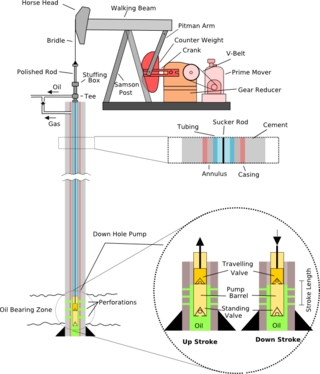
A pumpjack is the overground drive for a reciprocating piston pump in an oil well.

A gas lift or bubble pump is a type of pump that can raise fluid between elevations by introducing gas bubbles into a vertical outlet tube; as the bubbles rise within the tube they cause a drop in the hydrostatic pressure behind them, causing the fluid to be pulled up. Gas lifts are commonly used as artificial lifts for water or oil, using compressed air or water vapor.

<span class="mw-page-title-main">Christmas tree (oil well)</span> Assembly of valves, spools, and fittings used to regulate the flow of fluids in an oil well

In petroleum and natural gas extraction, a Christmas tree, or tree, is an assembly of valves, casing spools, and fittings used to regulate the flow of pipes in an oil well, gas well, water injection well, water disposal well, gas injection well, condensate well, and other types of well.

<span class="mw-page-title-main">Hydraulic cylinder</span> Mechanical tool for applying force

A hydraulic cylinder is a mechanical actuator that is used to give a unidirectional force through a unidirectional stroke. It has many applications, notably in construction equipment, manufacturing machinery, elevators, and civil engineering. A hydraulic cylinder is a hydraulic actuator that provides linear motion when hydraulic energy is converted into mechanical movement. It can be likened to a muscle in that, when the hydraulic system of a machine is activated, the cylinder is responsible for providing the motion.

<span class="mw-page-title-main">Blowout preventer</span> Specialized valve

A blowout preventer (BOP) is a specialized valve or similar mechanical device, used to seal, control and monitor oil and gas wells to prevent blowouts, the uncontrolled release of crude oil or natural gas from a well. They are usually installed in stacks of other valves.

<span class="mw-page-title-main">Drill stem test</span>

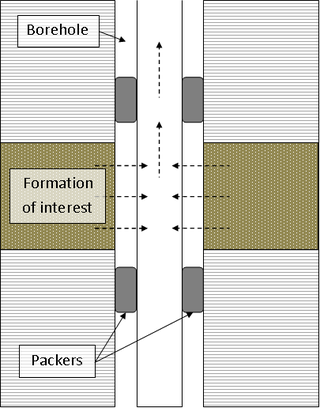
A drill stem test (DST) is a procedure for isolating and testing the pressure, permeability and productive capacity of a geological formation during the drilling of a well. The test is an important measurement of pressure behaviour at the drill stem and is a valuable way of obtaining information on the formation fluid and establishing whether a well has found a commercial hydrocarbon reservoir.

<span class="mw-page-title-main">Extraction of petroleum</span> Removal of petroleum from the earth

Petroleum is a fossil fuel that can be drawn from beneath the earth's surface. Reservoirs of petroleum are formed through the mixture of plants, algae, and sediments in shallow seas under high pressure. Petroleum is mostly recovered from oil drilling. Seismic surveys and other methods are used to locate oil reservoirs. Oil rigs and oil platforms are used to drill long holes into the earth to create an oil well and extract petroleum. After extraction, oil is refined to make gasoline and other products such as tires and refrigerators. Extraction of petroleum can be dangerous and have led to oil spills.

Gas well deliquification, also referred to as "gas well dewatering", is the general term for technologies used to remove water or condensates build-up from producing gas wells.

<span class="mw-page-title-main">Coiled tubing</span> Long metal pipe used in oil and gas wells

In the oil and gas industry, coiled tubing refers to a long metal pipe, normally 1 to 3.25 in in diameter which is supplied spooled on a large reel. It is used for interventions in oil and gas wells and sometimes as production tubing in depleted gas wells. Coiled tubing is often used to carry out operations similar to wirelining. The main benefits over wireline are the ability to pump chemicals through the coil and the ability to push it into the hole rather than relying on gravity. Pumping can be fairly self-contained, almost a closed system, since the tube is continuous instead of jointed pipe. For offshore operations, the 'footprint' for a coiled tubing operation is generally larger than a wireline spread, which can limit the number of installations where coiled tubing can be performed and make the operation more costly. A coiled tubing operation is normally performed through the drilling derrick on the oil platform, which is used to support the surface equipment, although on platforms with no drilling facilities a self-supporting tower can be used instead. For coiled tubing operations on sub-sea wells a mobile offshore drilling unit (MODU) e.g. semi-submersible, drillship etc. has to be utilized to support all the surface equipment and personnel, whereas wireline can be carried out from a smaller and cheaper intervention vessel. Onshore, they can be run using smaller service rigs, and for light operations a mobile self-contained coiled tubing rig can be used.

Slickline refers to a single strand wire which is used to run a variety of tools down into the wellbore for several purposes. It is used during well drilling operations in the oil and gas industry. In general, it can also describe a niche of the industry that involves using a slickline truck or doing a slickline job. Slickline looks like a long, smooth, unbraided wire, often shiny, silver/chrome in appearance. It comes in varying lengths, according to the depth of wells in the area it is used up to 35,000 feet in length. It is used to lower and raise downhole tools used in oil and gas well maintenance to the appropriate depth of the drilled well.

A downhole safety valve refers to a component on an oil and gas well, which acts as a failsafe to prevent the uncontrolled release of reservoir fluids in the event of a worst-case-scenario surface disaster. It is almost always installed as a vital component on the completion.

<span class="mw-page-title-main">Completion (oil and gas wells)</span> Last operation for oil and gas wells

Well completion is the process of making a well ready for production after drilling operations. This principally involves preparing the bottom of the hole to the required specifications, running in the production tubing and its associated down hole tools as well as perforating and stimulating as required. Sometimes, the process of running in and cementing the casing is also included. After a well has been drilled, should the drilling fluids be removed, the well would eventually close in upon itself. Casing ensures that this will not happen while also protecting the wellstream from outside incumbents, like water or sand.

Downhole oil–water separation (DOWS) technologies are apparatuses and methods that separate production fluids into a petroleum-rich stream and water-rich stream within an oil well. A DOWS system installed in a borehole will receive the fluids from an oil-producing zone in an oil reservoir and separate the mixture into a stream that is mostly water and a stream that is primarily crude oil and natural gas and direct the streams to different destinations. After the separation in the borehole, DOWS systems pump the petroleum-rich stream to the surface and inject the water-rich stream into a different zone or formation accessible to the same wellbore.

Petroleum production engineering is a subset of petroleum engineering.

<span class="mw-page-title-main">Norris Production Solutions</span>

Dover Artificial Lift is an oilfield services company headquartered in The Woodlands, Texas. The company provides products and services for artificial lift during production of petroleum and natural gas. Dover Artificial Lift was a member of Dover Corporation until 2018, when it was spun off as part of Apergy Energy.

References

References

  1. Hari, S.; Krishna, Shanker; Patel, Manav; Bhatia, Pooja; Vij, Rakesh Kumar (1 June 2022). "Influence of wellhead pressure and water cut in the optimization of oil production from gas lifted wells". Petroleum Research. 7 (2): 253–262. Bibcode:2022PetRe...7..253H. doi: 10.1016/j.ptlrs.2021.09.008 . ISSN   2096-2495. S2CID   239227477.