
Bandwidth is the difference between the upper and lower frequencies in a continuous band of frequencies. It is typically measured in hertz, and depending on context, may specifically refer to passband bandwidth or baseband bandwidth. Passband bandwidth is the difference between the upper and lower cutoff frequencies of, for example, a band-pass filter, a communication channel, or a signal spectrum. Baseband bandwidth applies to a low-pass filter or baseband signal; the bandwidth is equal to its upper cutoff frequency.

In telecommunications, orthogonal frequency-division multiplexing (OFDM) is a type of digital transmission used in digital modulation for encoding digital (binary) data on multiple carrier frequencies. OFDM has developed into a popular scheme for wideband digital communication, used in applications such as digital television and audio broadcasting, DSL internet access, wireless networks, power line networks, and 4G/5G mobile communications.

The Nyquist–Shannon sampling theorem is an essential principle for digital signal processing linking the frequency range of a signal and the sample rate required to avoid a type of distortion called aliasing. The theorem states that the sample rate must be at least twice the bandwidth of the signal to avoid aliasing distortion. In practice, it is used to select band-limiting filters to keep aliasing distortion below an acceptable amount when an analog signal is sampled or when sample rates are changed within a digital signal processing function.

In signal processing, the Nyquist rate, named after Harry Nyquist, is a value equal to twice the highest frequency (bandwidth) of a given function or signal. When the function is digitized at a higher sample rate, the resulting discrete-time sequence is said to be free of the distortion known as aliasing. Conversely, for a given sample-rate the corresponding Nyquist frequency in Hz is one-half the sample-rate. Note that the Nyquist rate is a property of a continuous-time signal, whereas Nyquist frequency is a property of a discrete-time system.
A low-pass filter is a filter that passes signals with a frequency lower than a selected cutoff frequency and attenuates signals with frequencies higher than the cutoff frequency. The exact frequency response of the filter depends on the filter design. The filter is sometimes called a high-cut filter, or treble-cut filter in audio applications. A low-pass filter is the complement of a high-pass filter.
The Whittaker–Shannon interpolation formula or sinc interpolation is a method to construct a continuous-time bandlimited function from a sequence of real numbers. The formula dates back to the works of E. Borel in 1898, and E. T. Whittaker in 1915, and was cited from works of J. M. Whittaker in 1935, and in the formulation of the Nyquist–Shannon sampling theorem by Claude Shannon in 1949. It is also commonly called Shannon's interpolation formula and Whittaker's interpolation formula. E. T. Whittaker, who published it in 1915, called it the Cardinal series.

In signal processing and related disciplines, aliasing is the overlapping of frequency components resulting from a sample rate below the Nyquist frequency. This overlap results in distortion or artifacts when the signal is reconstructed from samples which causes the reconstructed signal to differ from the original continuous signal. Aliasing that occurs in signals sampled in time, for instance in digital audio or the stroboscopic effect, is referred to as temporal aliasing. Aliasing in spatially sampled signals is referred to as spatial aliasing.

In signal processing, sampling is the reduction of a continuous-time signal to a discrete-time signal. A common example is the conversion of a sound wave to a sequence of "samples". A sample is a value of the signal at a point in time and/or space; this definition differs from the term's usage in statistics, which refers to a set of such values.
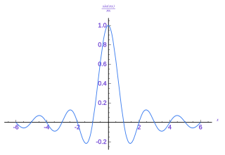
In signal processing, a sinc filter is an idealized filter that removes all frequency components above a given cutoff frequency, without affecting lower frequencies, and has linear phase response. The filter's impulse response is a sinc function in the time domain and its frequency response is a rectangular function. It is an "ideal" low-pass filter in the frequency sense, perfectly passing low frequencies, perfectly cutting high frequencies; and thus may be considered to be a brick-wall filter.
In signal processing, a finite impulse response (FIR) filter is a filter whose impulse response is of finite duration, because it settles to zero in finite time. This is in contrast to infinite impulse response (IIR) filters, which may have internal feedback and may continue to respond indefinitely.
An anti-aliasing filter (AAF) is a filter used before a signal sampler to restrict the bandwidth of a signal to satisfy the Nyquist–Shannon sampling theorem over the band of interest. Since the theorem states that unambiguous reconstruction of the signal from its samples is possible when the power of frequencies above the Nyquist frequency is zero, a brick wall filter is an idealized but impractical AAF. A practical AAF makes a trade off between reduced bandwidth and increased aliasing. A practical anti-aliasing filter will typically permit some aliasing to occur or attenuate or otherwise distort some in-band frequencies close to the Nyquist limit. For this reason, many practical systems sample higher than would be theoretically required by a perfect AAF in order to ensure that all frequencies of interest can be reconstructed, a practice called oversampling.
In digital signal processing, downsampling, compression, and decimation are terms associated with the process of resampling in a multi-rate digital signal processing system. Both downsampling and decimation can be synonymous with compression, or they can describe an entire process of bandwidth reduction (filtering) and sample-rate reduction. When the process is performed on a sequence of samples of a signal or a continuous function, it produces an approximation of the sequence that would have been obtained by sampling the signal at a lower rate.
In signal processing, oversampling is the process of sampling a signal at a sampling frequency significantly higher than the Nyquist rate. Theoretically, a bandwidth-limited signal can be perfectly reconstructed if sampled at the Nyquist rate or above it. The Nyquist rate is defined as twice the bandwidth of the signal. Oversampling is capable of improving resolution and signal-to-noise ratio, and can be helpful in avoiding aliasing and phase distortion by relaxing anti-aliasing filter performance requirements.
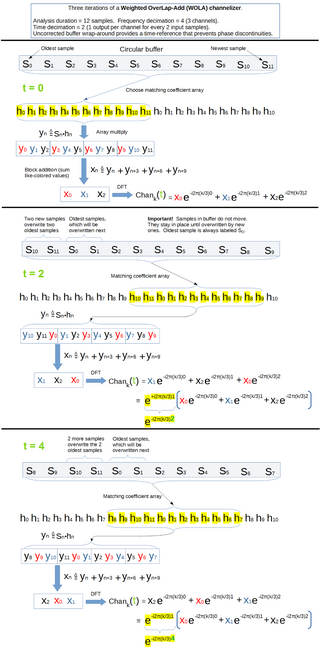
In signal processing, a filter bank is an array of bandpass filters that separates the input signal into multiple components, each one carrying a single frequency sub-band of the original signal. One application of a filter bank is a graphic equalizer, which can attenuate the components differently and recombine them into a modified version of the original signal. The process of decomposition performed by the filter bank is called analysis ; the output of analysis is referred to as a subband signal with as many subbands as there are filters in the filter bank. The reconstruction process is called synthesis, meaning reconstitution of a complete signal resulting from the filtering process.
Delta-sigma modulation is an oversampling method for encoding analog signals into digital signals as found in an analog-to-digital converter (ADC). It is also used to convert high-bitdepth digital signals into low-bit, high-frequency digital signals as part of the process to convert digital signals into analog as part of a digital-to-analog converter (DAC).
The raised-cosine filter is a filter frequently used for pulse-shaping in digital modulation due to its ability to minimise intersymbol interference (ISI). Its name stems from the fact that the non-zero portion of the frequency spectrum of its simplest form is a cosine function, 'raised' up to sit above the (horizontal) axis.
In communications, the Nyquist ISI criterion describes the conditions which, when satisfied by a communication channel, result in no intersymbol interference or ISI. It provides a method for constructing band-limited functions to overcome the effects of intersymbol interference.
The zero-order hold (ZOH) is a mathematical model of the practical signal reconstruction done by a conventional digital-to-analog converter (DAC). That is, it describes the effect of converting a discrete-time signal to a continuous-time signal by holding each sample value for one sample interval. It has several applications in electrical communication.
First-order hold (FOH) is a mathematical model of the practical reconstruction of sampled signals that could be done by a conventional digital-to-analog converter (DAC) and an analog circuit called an integrator. For FOH, the signal is reconstructed as a piecewise linear approximation to the original signal that was sampled. A mathematical model such as FOH (or, more commonly, the zero-order hold) is necessary because, in the sampling and reconstruction theorem, a sequence of Dirac impulses, xs(t), representing the discrete samples, x(nT), is low-pass filtered to recover the original signal that was sampled, x(t). However, outputting a sequence of Dirac impulses is impractical. Devices can be implemented, using a conventional DAC and some linear analog circuitry, to reconstruct the piecewise linear output for either predictive or delayed FOH.
This article provides a short survey of the concepts, principles and applications of Multirate Filter Banks and Multidimensional Directional Filter Banks.


