Offshore geotechnical engineering

Last updated

Platforms offshore Mexico. Offshore platforms.jpg
Platforms offshore Mexico.

Offshore geotechnical engineering is a sub-field of geotechnical engineering. It is concerned with foundation design, construction, maintenance and decommissioning for human-made structures in the sea. [1] Oil platforms, artificial islands and submarine pipelines are examples of such structures. The seabed has to be able to withstand the weight of these structures and the applied loads. Geohazards must also be taken into account. The need for offshore developments stems from a gradual depletion of hydrocarbon reserves onshore or near the coastlines, as new fields are being developed at greater distances offshore and in deeper water, [2] with a corresponding adaptation of the offshore site investigations. [3] Today, there are more than 7,000 offshore platforms operating at a water depth up to and exceeding 2000 m. [2] A typical field development extends over tens of square kilometers, and may comprise several fixed structures, infield flowlines with an export pipeline either to the shoreline or connected to a regional trunkline. [4]

Contents

Differences between onshore and offshore geotechnical engineering

An offshore environment has several implications for geotechnical engineering. These include the following: [1] [4]

The offshore environment

Offshore structures are exposed to various environmental loads: wind, waves, currents and, in cold oceans, sea ice and icebergs. [6] [7] Environmental loads act primarily in the horizontal direction, but also have a vertical component. Some of these loads get transmitted to the foundation (the seabed). Wind, wave and current regimes can be estimated from meteorological and oceanographic data, which are collectively referred to as metocean data. Earthquake-induced loading can also occur – they proceed in the opposite direction: from the foundation to the structure. Depending on location, other geohazards may also be an issue. All of these phenomena may affect the integrity or the serviceability of the structure and its foundation during its operational lifespan – they need to be taken into account in offshore design.

The nature of the soil

Following are some to the features characterizing the soil in an offshore environment: [8]

Metocean aspects

Wave action against an offshore structure.

Wave forces induce motion of floating structures in all six degrees of freedom – they are a major design criterion for offshore structures. [9] [note 1] When a wave's orbital motion reaches the seabed, it induces sediment transport. This only occurs to a water depth of about 200 metres (660 ft), which is the commonly adopted boundary between shallow water and deep water. The reason is that the orbital motion only extends to a water depth that is half the wavelength, and the maximum possible wavelength is generally considered to be 400 metres (1,300 ft). [7] In shallow water, waves may generate pore pressure build-up in the soil, which may lead to flow slide, and repeated impact on a platform may cause liquefaction, and loss of support. [7]

Currents are a source of horizontal loading for offshore structures. Because of the Bernoulli effect, they may also exert upward or downward forces on structural surfaces and can induce the vibration of wire lines and pipelines. [7] Currents are responsible for eddies around a structure, which cause scouring and erosion of the soil. [7] There are various types of currents: oceanic circulation, geostrophic, tidal, wind-driven, and density currents. [7]

Geohazards

Usgs-of99-570 mud volcano.png
Two types of seismic profiles (top: chirp; bottom: Water gun) of a fault within the seabed in the Gulf of Mexico.
Worldwide distribution of gas hydrates 1996.jpg
Worldwide distribution of gas hydrates, which are another potential hazard for offshore developments.
US Navy 020624-N-5329L-002 ^ldquo,Klein 5000^rdquo,side scan sonar.jpg
An example of a side scan sonar, a device used to survey the seabed.
Monterey Canyon system.jpg
A 3-D image of the Monterey Canyon system, an example of what can be obtained from multibeam echosounders.

Geohazards are associated with geological activity, geotechnical features and environmental conditions. Shallow geohazards are those occurring at less than 400 metres (1,300 ft) below the seafloor. [10] Information on the potential risks associated with these phenomena is acquired through studies of the geomorphology, geological setting and tectonic framework in the area of interest, as well as with geophysical and geotechnical surveys of the seafloor. [5] Examples of potential threats include tsunamis, landslides, active faults, mud diapirs and the nature of the soil layering (presence of karst, gas hydrates, carbonates). [10] [11] [12] In cold regions, gouging ice features are a threat to subsea installations, such as pipelines. [13] [14] [5] The risks associated with a particular type of geohazard is a function of how exposed the structure is to the event, how severe this event is and how often it occurs (for episodic events). Any threat has to be monitored, and mitigated for or removed. [15] [16]

Site investigation

Offshore site investigations are not unlike those conducted onshore (see Geotechnical investigation). They may be divided into three phases: [17]

Desk study

In this phase, which may take place over a period of several months (depending on project size), information is gathered from various sources, including reports, scientific literature (journal articles, conference proceedings) and databases, with the purpose of evaluating risks, assessing design options and planning the subsequent phases. Bathymetry, regional geology, potential geohazards, seabed obstacles and metocean data [17] [18] are some of the information that are sought after during that phase.

Geophysical surveys

Geophysical surveys can be used for various purposes. One is to study the bathymetry in the location of interest and to produce an image of the seafloor (irregularities, objects on the seabed, lateral variability, ice gouges, ...). Seismic refraction surveys can be done to obtain information on shallow seabed stratigraphy – it can also be used to locate material such as sand, sand deposit and gravel for use in the construction of artificial islands. [19] Geophysical surveys are conducted from a research vessel equipped with sonar devices and related equipment, such as single-beam and multibeam echosounders, side-scan sonars, ‘towfish’ and remotely operated vehicles (ROVs). [20] [21] For the sub-bottom stratigraphy, the tools used include boomers, sparkers, pingers and chirp. [22] Geophysical surveys are normally required before conducting the geotechnical surveys; in larger projects, these phases may be interwoven. [22]

Geotechnical surveys

Geotechnical surveys involve a combination of sampling, drilling, in situ testing as well as laboratory soil testing that is conducted offshore and, with samples, onshore. They serve to ground truth the results of the geophysical investigations; they also provide a detailed account of the seabed stratigraphy and soil engineering properties. [23] Depending on water depth and metocean conditions, geotechnical surveys may be conducted from a dedicated geotechnical drillship, a semi-submersible, a jackup rig, a large hovercraft or other means. [24] They are done at a series of specific locations, while the vessel maintains a constant position. Dynamic positioning and mooring with four-point anchoring systems are used for that purpose.

Shallow penetration geotechnical surveys may include soil sampling of the seabed surface or in situ mechanical testing. They are used to generate information on the physical and mechanical properties of the seabed. [25] They extend to the first few meters below the mudline. Surveys done to these depths, which may be conducted at the same time as the shallow geophysical survey, may suffice if the structure to be deployed at that location is relatively light. These surveys are also useful for planning subsea pipeline routes.

The purpose of deep penetration geotechnical surveys is to collect information on the seabed stratigraphy to depths extending up to a few 100 meters below the mudline. [10] [26] These surveys are done when larger structures are planned at these locations. Deep drill holes require a few days during which the drilling unit has to remain exactly in the same position (see dynamic positioning).

Sampling and drilling

Gravity-corer hg.png
A gravity-driven soil sampler, used for coring the seabed.
Deepwater drilling systems 2.png
A gravity-driven soil sampler, used for coring the seabed.
Box corer for extracting soil samples from the seabed. Giant-box-corer hg.jpg
Box corer for extracting soil samples from the seabed.

Seabed surface sampling can be done with a grab sampler and with a box corer. [27] The latter provides undisturbed specimens, on which testing can be conducted, for instance, to determine the soil's relative density, water content and mechanical properties. Sampling can also be achieved with a tube corer, either gravity-driven, or that can be pushed into the seabed by a piston or by means of a vibration system (a device called a vibrocorer). [28]

Drilling is another means of sampling the seabed. It is used to obtain a record of the seabed stratigraphy or the rock formations below it. The set-up used to sample an offshore structure's foundation is similar to that used by the oil industry to reach and delineate hydrocarbon reservoirs, with some differences in the types of testing. [29] The drill string consists of a series of pipe segments 5 inches (13 cm) in diameter screwed end to end, with a drillbit assembly at the bottom. [28] As the dragbit (teeth extending downward from the drillbit) cut into the soil, soil cuttings are produced. Viscous drilling mud flowing down the drillpipe collects these cuttings and carry them up outside the drillpipe. As is the case for onshore geotechnical surveys, different tools can be used for sampling the soil from a drill hole, notably "Shelby tubes", "piston samplers" and "split spoon samplers".

In situ soil testing

Cone penetrometer.svg
Diagram showing the principle of a cone penetrometer to obtain the soil's strength profile.
Shear vane sketch.svg
Diagram showing the principle of a shear vane to measure the soil's peak strength and residual strength.

Information on the mechanical strength of the soil can be obtained in situ (from the seabed itself as opposed to in a laboratory from a soil sample). The advantage of this approach is that the data are obtained from soil that has not suffered any disturbance as a result of its relocation. Two of the most commonly used instruments used for that purpose are the cone penetrometer (CPT) and the shear vane. [30] [31]

The CPT is a rod-shaped tool whose end has the shape of a cone with a known apex angle (e.g. 60 degrees). [32] As it is pushed into the soil, the resistance to penetration is measured, thereby providing an indication of soil strength. [33] A sleeve behind the cone allows the independent determination of the frictional resistance. Some cones are also able to measure pore water pressure. The shear vane test is used to determine the undrained shear strength of soft to medium cohesive soils. [34] [35] This instrument usually consists of four plates welded at 90 degrees from each other at the end of a rod. The rod is then inserted into the soil and a torque is applied to it so as to achieve a constant rotation rate. The torque resistance is measured and an equation is then used to determine the undrained shear strength (and the residual strength), which takes into account the vane's size and geometry. [35]

Offshore structures and geotechnical considerations

Offshore structures are mainly represented by platforms, notably jackup rigs, steel jacket structures and gravity-based structures. [36] The nature of the seabed has to be taken into account when planning these developments. For instance, a gravity-based structure typically has a very large footprint and is relatively buoyant (because it encloses a large open volume). [37] Under these circumstances, vertical loading of the foundation may not be as significant as the horizontal loads exerted by wave actions and transferred to the seabed. In that scenario, sliding could be the dominant mode of failure. A more specific example is that of the Woodside "North Rankin A" steel jacket structure offshore Australia. [38] The shaft capacity for the piles making up each of the structure's legs was estimated on the basis of conventional design methods, notably when driven into siliceous sands. But the soil at that site was a lower capacity calcareous sand. Costly remediation measures were required to correct this oversight.

Proper seabed characterization is also required for mooring systems. For instance, the design and installation of suction piles has to take into account the soil properties, notably its undrained shear strength. [39] The same is true for the installation and capacity assessment of plate anchors. [40]

Submarine pipelines

Submarine pipelines are another common type of man-made structure in the offshore environment. [41] These structures either rest on the seabed, or are placed inside a trench to protect them from fishing trawlers, dragging anchors or fatigue due current-induced oscillations. [42] Trenching is also used to protect pipelines from gouging by ice keels. [13] [14] In both cases, planning of the pipeline involves geotechnical considerations. Pipelines resting on the seabed require geotechnical data along the proposed pipeline route to evaluate potential stability issues, such as passive failure of the soil below it (the pipeline drops) due to insufficient bearing capacity, or sliding failure (the pipeline shift sideways), due to low sliding resistance. [43] [44] The process of trenching, when required, needs to take into account soil properties and how they would affect ploughing duration. [45] Buckling potential induced by the axial and transverse response of the buried pipeline during its operational lifespan need to be assessed at the planning phase, and this will depend on the resistance of the enclosing soil. [44]

Offshore embedded anchors

Offshore embedded anchors are anchors that derive their capacity from the frictional and/or bearing resistance of the soil surrounding them. This is converse to gravity anchors that derive their capacity from their weight. As offshore developments move into deeper waters, gravity based structures become less economical due to the large required size and cost of transportation. This proves opportune for the employment of embedded anchors.

See also

Notes

  1. For instance, a given structure may undergo 2x10⁸ wave cycles during its design service life.

Related Research Articles

<span class="mw-page-title-main">Geotechnical engineering</span> Scientific study of earth materials in engineering problems

Geotechnical engineering, also known as geotechnics, is the branch of civil engineering concerned with the engineering behavior of earth materials. It uses the principles of soil mechanics and rock mechanics to solve its engineering problems. It also relies on knowledge of geology, hydrology, geophysics, and other related sciences.

<span class="mw-page-title-main">Oil platform</span> Offshore ocean structure with oil drilling and related facilities

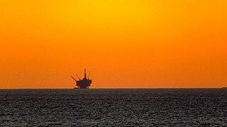
An oil platform is a large structure with facilities to extract and process petroleum and natural gas that lie in rock formations beneath the seabed. Many oil platforms will also have facilities to accommodate the workers, although it is also common to have a separate accommodation platform bridge linked to the production platform. Most commonly, oil platforms engage in activities on the continental shelf, though they can also be used in lakes, inshore waters, and inland seas. Depending on the circumstances, the platform may be fixed to the ocean floor, consist of an artificial island, or float. In some arrangements the main facility may have storage facilities for the processed oil. Remote subsea wells may also be connected to a platform by flow lines and by umbilical connections. These sub-sea facilities may include one or more subsea wells or manifold centres for multiple wells.

<span class="mw-page-title-main">Offshore construction</span> Installation of structures and facilities in a marine environment

Offshore construction is the installation of structures and facilities in a marine environment, usually for the production and transmission of electricity, oil, gas and other resources. It is also called maritime engineering.

<span class="mw-page-title-main">Foundation (engineering)</span> Lowest and supporting layer of a structure

In engineering, a foundation is the element of a structure which connects it to the ground or more rarely, water, transferring loads from the structure to the ground. Foundations are generally considered either shallow or deep. Foundation engineering is the application of soil mechanics and rock mechanics in the design of foundation elements of structures.

<span class="mw-page-title-main">Engineering geology</span> Application of geology to engineering practice

Engineering geology is the application of geology to engineering study for the purpose of assuring that the geological factors regarding the location, design, construction, operation and maintenance of engineering works are recognized and accounted for. Engineering geologists provide geological and geotechnical recommendations, analysis, and design associated with human development and various types of structures. The realm of the engineering geologist is essentially in the area of earth-structure interactions, or investigation of how the earth or earth processes impact human made structures and human activities.

<span class="mw-page-title-main">Seabed gouging by ice</span> Outcome of the interaction between drifting ice and the seabed

Seabed gouging by ice is a process that occurs when floating ice features drift into shallower areas and their keel comes into contact with the seabed. As they keep drifting, they produce long, narrow furrows most often called gouges, or scours. This phenomenon is common in offshore environments where ice is known to exist. Although it also occurs in rivers and lakes, it appears to be better documented from oceans and sea expanses.

<span class="mw-page-title-main">Geotechnical investigation</span> Work done to obtain information on the physical properties of soil earthworks and foundations

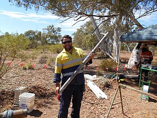
Geotechnical investigations are performed by geotechnical engineers or engineering geologists to obtain information on the physical properties of soil earthworks and foundations for proposed structures and for repair of distress to earthworks and structures caused by subsurface conditions; this type of investigation is called a site investigation. Geotechnical investigations are also used to measure the thermal resistance of soils or backfill materials required for underground transmission lines, oil and gas pipelines, radioactive waste disposal, and solar thermal storage facilities. A geotechnical investigation will include surface exploration and subsurface exploration of a site. Sometimes, geophysical methods are used to obtain data about sites. Subsurface exploration usually involves soil sampling and laboratory tests of the soil samples retrieved.

<span class="mw-page-title-main">Deep foundation</span> Type of foundation

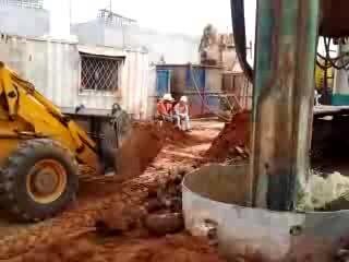
A deep foundation is a type of foundation that transfers building loads to the earth farther down from the surface than a shallow foundation does to a subsurface layer or a range of depths. A pile or piling is a vertical structural element of a deep foundation, driven or drilled deep into the ground at the building site.

Marine architecture is the design of architectural and engineering structures which support coastal design, near-shore and off-shore or deep-water planning for many projects such as shipyards, ship transport, coastal management or other marine and/or hydroscape activities. These structures include harbors, lighthouses, marinas, oil platforms, offshore drillings, accommodation platforms and offshore wind farms, floating engineering structures and building architectures or civil seascape developments. Floating structures in deep water may use suction caisson for anchoring.

<span class="mw-page-title-main">Offshore drilling</span> Mechanical process where a wellbore is drilled below the seabed

Offshore drilling is a mechanical process where a wellbore is drilled below the seabed. It is typically carried out in order to explore for and subsequently extract petroleum that lies in rock formations beneath the seabed. Most commonly, the term is used to describe drilling activities on the continental shelf, though the term can also be applied to drilling in lakes, inshore waters and inland seas.

Subsea technology involves fully submerged ocean equipment, operations, or applications, especially when some distance offshore, in deep ocean waters, or on the seabed. The term subsea is frequently used in connection with oceanography, marine or ocean engineering, ocean exploration, remotely operated vehicle (ROVs) autonomous underwater vehicles (AUVs), submarine communications or power cables, seafloor mineral mining, oil and gas, and offshore wind power.

"Offshore", when used in relation to hydrocarbons, refers to operations undertaken at, or under the, sea in association with an oil, natural gas or condensate field that is under the seabed, or to activities carried out in relation to such a field. Offshore is part of the upstream sector of the oil and gas industry.

<span class="mw-page-title-main">Fixed platform</span> Type of offshore platform used for the extraction of petroleum or gas

A fixed platform is a type of offshore platform used for the extraction of petroleum or gas. These platforms are built on concrete and/or steel legs anchored directly onto the seabed, supporting a deck with space for drilling rigs, production facilities and crew quarters. Such platforms are, by virtue of their immobility, designed for very long-term use. Various types of structure are used, steel jacket, concrete caisson, floating steel and even floating concrete. Steel jackets are vertical sections made of tubular steel members, and are usually piled into the seabed. Concrete caisson structures, pioneered by the Condeep concept, often have in-built oil storage in tanks below the sea surface and these tanks were often used as a flotation capability, allowing them to be built close to shore and then floated to their final position where they are sunk to the seabed. Fixed platforms are economically feasible for installation in water depths up to about 500 feet ; for deeper depths a floating production system, or a subsea pipeline to land or to shallower water depths for processing, would usually be considered.

<span class="mw-page-title-main">Suction caisson</span> Open bottomed tube anchor embedded and released by pressure differential

Suction caissons are a form of fixed platform anchor in the form of an open bottomed tube embedded in the sediment and sealed at the top while in use so that lifting forces generate a pressure differential that holds the caisson down. They have a number of advantages over conventional offshore foundations, mainly being quicker to install than deep foundation piles and being easier to remove during decommissioning. Suction caissons are now used extensively worldwide for anchoring large offshore installations, like oil platforms, offshore drillings and accommodation platforms to the seafloor at great depths. In recent years, suction caissons have also seen usage for offshore wind turbines in shallower waters.

<span class="mw-page-title-main">Submarine pipeline</span> Pipeline that is laid on the seabed or below it inside a trench

A submarine pipeline is a pipeline that is laid on the seabed or below it inside a trench. In some cases, the pipeline is mostly on-land but in places it crosses water expanses, such as small seas, straits and rivers. Submarine pipelines are used primarily to carry oil or gas, but transportation of water is also important. A distinction is sometimes made between a flowline and a pipeline. The former is an intrafield pipeline, in the sense that it is used to connect subsea wellheads, manifolds and the platform within a particular development field. The latter, sometimes referred to as an export pipeline, is used to bring the resource to shore. Sizeable pipeline construction projects need to take into account many factors, such as the offshore ecology, geohazards and environmental loading – they are often undertaken by multidisciplinary, international teams.

<span class="mw-page-title-main">Subsea production system</span> Wells located on the seabed

Subsea production systems are typical wells located on the seabed, shallow or deep water. Generally termed as Floating production system, where the petroleum is extracted at the seabed and the same can be tied back to an already existing production platform or an onshore facility. The oil platform well is drilled by a movable rig and the extracted oil or natural gas is transported by submarine pipeline under the sea and then to rise to a processing facility. It is classified into

<span class="mw-page-title-main">Strudel (ice)</span> Vertical hole in sea ice

A strudel is a vertical hole in sea ice through which downward jet-like, buoyancy-driven drainage of flood water is thought to occur. This feature is less than a few tens of meters in size and typically occurs within 30 km from a river mouth, in the sea ice expanse that is fastened to the coastline. Once the water that flooded the ice has completely drained off the ice surface, strudel become recognizable by a radial pattern of feeder channels that lead to the hole. They are elongated and irregularly spaced, with the larger ones up to several kilometers apart. Their distribution tends to be controlled by weak areas in the ice – in places, they line up along fractures or refrozen extensional cracks. The ice sheet where they occur may be 2 m in thickness, at water depths in the order of a few meters.

<span class="mw-page-title-main">Offshore embedded anchors</span> Type of marine mooring component

Offshore embedded anchors are anchors intended for offshore use that derive their holding capacity from the frictional, or bearing, resistance of the surrounding soil, as opposed to gravity anchors, which derive their holding capacity largely from their weight. As offshore developments move into deeper waters, gravity-based structures become less economical due to the large size needed and the consequent cost of transportation.

Susan Gourvenec is a British geoscientist who is Professor of Offshore Geotechnical Engineering and deputy director of the Southampton Marine and Maritime Institute at the University of Southampton. She was elected a Fellow of the Royal Academy of Engineering in 2022.

Marine construction is the process of building structures in or adjacent to large bodies of water, usually the sea. These structures can be built for a variety of purposes, including transportation, energy production, and recreation. Marine construction can involve the use of a variety of building materials, predominantly steel and concrete. Some examples of marine structures include ships, offshore platforms, moorings, pipelines, cables, wharves, bridges, tunnels, breakwaters and docks. Marine construction may require diving work, but professional diving is expensive and dangerous, and may involve relatively high risk, and the types of tools and equipment that can both function underwater and be safely used by divers are limited. Remotely operated underwater vehicles (ROVs) and other types of submersible equipment are a lower risk alternative, but they are also expensive and limited in applications, so when reasonably practicable, most underwater construction involves either removing the water from the building site by dewatering behind a cofferdam or inside a caisson, or prefabrication of structural units off-site with mainly assembly and installation done on-site.

References

  1. 1 2 Dean, p. 1
  2. 1 2 Randolph & Gourvenec, p. 1
  3. Kolk & Wegerif, 2005
  4. 1 2 Randolph & Gourvenec, p. 3
  5. 1 2 3 Cardenas et al. 2022
  6. Randolph & Gourvenec, Section 2.4
  7. 1 2 3 4 5 6 Gerwick, 2000
  8. Randolph & Gourvenec, Section 2.3
  9. Randolph & Gourvenec, p. 24
  10. 1 2 3 Peuchen and Raap, 2007.
  11. Randolph & Gourvenec, Fig. 3.14
  12. Kolk & Wegerif, p. 151
  13. 1 2 Palmer and Been, 2011
  14. 1 2 Barrette 2011
  15. Hogan et al., 2008
  16. Younes et al., 2005
  17. 1 2 Randolph & Gourvenec, Chap. 3
  18. Dean, section 1.4
  19. Dean, p. 33
  20. Dean, section 2.2
  21. Randolph & Gourvenec, p. 34
  22. 1 2 Randolph & Gourvenec, p. 32
  23. Randolph & Gourvenec, p. 31
  24. Dean, p. 47
  25. Dean, section 2.3
  26. Dean, section 2.4
  27. Dean, Fig. 2.5
  28. 1 2 Dean, p. 43
  29. Randolph & Gourvenec, p. 44
  30. Dean, section 2.3.4
  31. Newson et al., 2004
  32. Dean, p. 45
  33. Das, p. 646
  34. Dean, p. 60
  35. 1 2 Das, p. 406
  36. Dean, 2010
  37. Ramakrishnan, p. 9
  38. Randolph and Gourvenec, p. 146
  39. Bai and Bai, pp. 121, 129
  40. Bai and Bai, p. 131
  41. Palmer and King 2008
  42. Ramakrishnan, p. 186
  43. Zhang and Erbrich, 2005
  44. 1 2 Catie et al., 2005
  45. Bransby et al., 2005

Bibliography