Optical microscope

Last updated

Scientist using an optical microscope in a laboratory Scientists are working in the lab.9.jpg
Scientist using an optical microscope in a laboratory

The optical microscope, also referred to as a light microscope, is a type of microscope that commonly uses visible light and a system of lenses to generate magnified images of small objects. Optical microscopes are the oldest design of microscope and were possibly invented in their present compound form in the 17th century. Basic optical microscopes can be very simple, although many complex designs aim to improve resolution and sample contrast.

Contents

The object is placed on a stage and may be directly viewed through one or two eyepieces on the microscope. In high-power microscopes, both eyepieces typically show the same image, but with a stereo microscope, slightly different images are used to create a 3-D effect. A camera is typically used to capture the image (micrograph).

The sample can be lit in a variety of ways. Transparent objects can be lit from below and solid objects can be made visible using light coming from below (bright field) or around (dark field) the objective lens. Polarised light may be used to determine crystal orientation of metallic objects. Phase-contrast imaging can be used to increase image contrast by highlighting small details of differing refractive index.

A range of objective lenses with different magnification are usually provided mounted on a turret, allowing them to be rotated into place and providing an ability to zoom-in. The maximum magnification power of optical microscopes is typically limited to around 1000x because of the limited resolving power of visible light. While larger magnifications are possible no additional details of the object are resolved.

Alternatives to optical microscopy which do not use visible light include scanning electron microscopy and transmission electron microscopy and scanning probe microscopy and as a result, can achieve much greater magnifications.

Types

Diagram of a simple microscope Microscope simple diagram.png
Diagram of a simple microscope

There are two basic types of optical microscopes: simple microscopes and compound microscopes. A simple microscope uses the optical power of a single lens or group of lenses for magnification. A compound microscope uses a system of lenses (one set enlarging the image produced by another) to achieve a much higher magnification of an object. The vast majority of modern research microscopes are compound microscopes, while some cheaper commercial digital microscopes are simple single-lens microscopes. Compound microscopes can be further divided into a variety of other types of microscopes, which differ in their optical configurations, cost, and intended purposes.

Simple microscope

A simple microscope uses a lens or set of lenses to enlarge an object through angular magnification alone, giving the viewer an erect enlarged virtual image. [1] [2] The use of a single convex lens or groups of lenses are found in simple magnification devices such as the magnifying glass, loupes, and eyepieces for telescopes and microscopes.

Compound microscope

Diagram of a compound microscope Microscope compound diagram.png
Diagram of a compound microscope

A compound microscope uses a lens close to the object being viewed to collect light (called the objective lens), which focuses a real image of the object inside the microscope (image 1). That image is then magnified by a second lens or group of lenses (called the eyepiece) that gives the viewer an enlarged inverted virtual image of the object (image 2). [3] The use of a compound objective/eyepiece combination allows for much higher magnification. Common compound microscopes often feature exchangeable objective lenses, allowing the user to quickly adjust the magnification. [3] A compound microscope also enables more advanced illumination setups, such as phase contrast.

Other microscope variants

There are many variants of the compound optical microscope design for specialized purposes. Some of these are physical design differences allowing specialization for certain purposes:

Other microscope variants are designed for different illumination techniques:

Digital microscope

A miniature USB microscope 2008Computex DnI Award AnMo Dino-Lite Digital Microscope.jpg
A miniature USB microscope

A digital microscope is a microscope equipped with a digital camera allowing observation of a sample via a computer. Microscopes can also be partly or wholly computer-controlled with various levels of automation. Digital microscopy allows greater analysis of a microscope image, for example, measurements of distances and areas and quantitation of a fluorescent or histological stain.

Low-powered digital microscopes, USB microscopes, are also commercially available. These are essentially webcams with a high-powered macro lens and generally do not use transillumination. The camera is attached directly to a computer's USB port to show the images directly on the monitor. They offer modest magnifications (up to about 200×) without the need to use eyepieces and at a very low cost. High-power illumination is usually provided by an LED source or sources adjacent to the camera lens.

Digital microscopy with very low light levels to avoid damage to vulnerable biological samples is available using sensitive photon-counting digital cameras. It has been demonstrated that a light source providing pairs of entangled photons may minimize the risk of damage to the most light-sensitive samples. In this application of ghost imaging to photon-sparse microscopy, the sample is illuminated with infrared photons, each spatially correlated with an entangled partner in the visible band for efficient imaging by a photon-counting camera. [7]

History

Invention

The earliest microscopes were single lens magnifying glasses with limited magnification, which date at least as far back as the widespread use of lenses in eyeglasses in the 13th century. [8]

Compound microscopes first appeared in Europe around 1620 [9] [10] including one demonstrated by Cornelis Drebbel in London (around 1621) and one exhibited in Rome in 1624. [11] [12]

The actual inventor of the compound microscope is unknown although many claims have been made over the years. These include a claim 35 [13] years after they appeared by Dutch spectacle-maker Johannes Zachariassen that his father, Zacharias Janssen, invented the compound microscope and/or the telescope as early as 1590. Johannes' testimony, which some claim is dubious, [14] [15] [16] pushes the invention date so far back that Zacharias would have been a child at the time, leading to speculation that, for Johannes' claim to be true, the compound microscope would have to have been invented by Johannes' grandfather, Hans Martens. [17] Another claim is that Janssen's competitor, Hans Lippershey (who applied for the first telescope patent in 1608) also invented the compound microscope. [18] Other historians point to the Dutch innovator Cornelis Drebbel with his 1621 compound microscope. [11] [12]

Galileo Galilei is sometimes cited as a compound microscope inventor. After 1610, he found that he could close focus his telescope to view small objects, such as flies, close up [19] and/or could look through the wrong end in reverse to magnify small objects. [20] The only drawback was that his 2 foot long telescope had to be extended out to 6 feet to view objects that close. [21] After seeing the compound microscope built by Drebbel exhibited in Rome in 1624, Galileo built his own improved version. [11] [12] In 1625, Giovanni Faber coined the name microscope for the compound microscope Galileo submitted to the Accademia dei Lincei in 1624 [22] (Galileo had called it the "occhiolino" or "little eye"). Faber coined the name from the Greek words μικρόν (micron) meaning "small", and σκοπεῖν (skopein) meaning "to look at", a name meant to be analogous with "telescope", another word coined by the Linceans. [23]

Christiaan Huygens, another Dutchman, developed a simple 2-lens ocular system in the late 17th century that was achromatically corrected, and therefore a huge step forward in microscope development. The Huygens ocular is still being produced to this day, but suffers from a small field size, and other minor disadvantages.

Popularization

The oldest published image known to have been made with a microscope: bees by Francesco Stelluti, 1630 Stelluti bees1630.jpg
The oldest published image known to have been made with a microscope: bees by Francesco Stelluti, 1630

Antonie van Leeuwenhoek (1632–1724) is credited with bringing the microscope to the attention of biologists, even though simple magnifying lenses were already being produced in the 16th century. Van Leeuwenhoek's home-made microscopes were simple microscopes, with a single very small, yet strong lens. They were awkward in use, but enabled van Leeuwenhoek to see detailed images. It took about 150 years of optical development before the compound microscope was able to provide the same quality image as van Leeuwenhoek's simple microscopes, due to difficulties in configuring multiple lenses. In the 1850s, John Leonard Riddell, Professor of Chemistry at Tulane University, invented the first practical binocular microscope while carrying out one of the earliest and most extensive American microscopic investigations of cholera. [25] [26]

Lighting techniques

While basic microscope technology and optics have been available for over 400 years it is much more recently that techniques in sample illumination were developed to generate the high quality images seen today.

In August 1893, August Köhler developed Köhler illumination. This method of sample illumination gives rise to extremely even lighting and overcomes many limitations of older techniques of sample illumination. Before development of Köhler illumination the image of the light source, for example a lightbulb filament, was always visible in the image of the sample.

The Nobel Prize in physics was awarded to Dutch physicist Frits Zernike in 1953 for his development of phase contrast illumination which allows imaging of transparent samples. By using interference rather than absorption of light, extremely transparent samples, such as live mammalian cells, can be imaged without having to use staining techniques. Just two years later, in 1955, Georges Nomarski published the theory for differential interference contrast microscopy, another interference-based imaging technique.

Fluorescence microscopy

Modern biological microscopy depends heavily on the development of fluorescent probes for specific structures within a cell. In contrast to normal transilluminated light microscopy, in fluorescence microscopy the sample is illuminated through the objective lens with a narrow set of wavelengths of light. This light interacts with fluorophores in the sample which then emit light of a longer wavelength. It is this emitted light which makes up the image.

Since the mid-20th century chemical fluorescent stains, such as DAPI which binds to DNA, have been used to label specific structures within the cell. More recent developments include immunofluorescence, which uses fluorescently labelled antibodies to recognise specific proteins within a sample, and fluorescent proteins like GFP which a live cell can express making it fluorescent.

Components

Basic optical transmission microscope elements (1990s) Optical microscope nikon alphaphot.jpg
Basic optical transmission microscope elements (1990s)

All modern optical microscopes designed for viewing samples by transmitted light share the same basic components of the light path. In addition, the vast majority of microscopes have the same 'structural' components [27] (numbered below according to the image on the right):

Eyepiece (ocular lens)

The eyepiece, or ocular lens, is a cylinder containing two or more lenses; its function is to bring the image into focus for the eye. The eyepiece is inserted into the top end of the body tube. Eyepieces are interchangeable and many different eyepieces can be inserted with different degrees of magnification. Typical magnification values for eyepieces include 5×, 10× (the most common), 15× and 20×. In some high performance microscopes, the optical configuration of the objective lens and eyepiece are matched to give the best possible optical performance. This occurs most commonly with apochromatic objectives.

Objective turret (revolver or revolving nose piece)

Objective turret, revolver, or revolving nose piece is the part that holds the set of objective lenses. It allows the user to switch between objective lenses.

Objective lens

At the lower end of a typical compound optical microscope, there are one or more objective lenses that collect light from the sample. The objective is usually in a cylinder housing containing a glass single or multi-element compound lens. Typically there will be around three objective lenses screwed into a circular nose piece which may be rotated to select the required objective lens. These arrangements are designed to be parfocal, which means that when one changes from one lens to another on a microscope, the sample stays in focus. Microscope objectives are characterized by two parameters, namely, magnification and numerical aperture. The former typically ranges from 5× to 100× while the latter ranges from 0.14 to 0.7, corresponding to focal lengths of about 40 to 2 mm, respectively. Objective lenses with higher magnifications normally have a higher numerical aperture and a shorter depth of field in the resulting image. Some high performance objective lenses may require matched eyepieces to deliver the best optical performance.

Oil immersion objective

Two Leica oil immersion microscope objective lenses: 100x (left) and 40x (right) Leica EpifluorescenceMicroscope ObjectiveLens.jpg
Two Leica oil immersion microscope objective lenses: 100× (left) and 40× (right)

Some microscopes make use of oil-immersion objectives or water-immersion objectives for greater resolution at high magnification. These are used with index-matching material such as immersion oil or water and a matched cover slip between the objective lens and the sample. The refractive index of the index-matching material is higher than air allowing the objective lens to have a larger numerical aperture (greater than 1) so that the light is transmitted from the specimen to the outer face of the objective lens with minimal refraction. Numerical apertures as high as 1.6 can be achieved. [28] The larger numerical aperture allows collection of more light making detailed observation of smaller details possible. An oil immersion lens usually has a magnification of 40 to 100×.

Focus knobs

Adjustment knobs move the stage up and down with separate adjustment for coarse and fine focusing. The same controls enable the microscope to adjust to specimens of different thickness. In older designs of microscopes, the focus adjustment wheels move the microscope tube up or down relative to the stand and had a fixed stage.

Frame

The whole of the optical assembly is traditionally attached to a rigid arm, which in turn is attached to a robust U-shaped foot to provide the necessary rigidity. The arm angle may be adjustable to allow the viewing angle to be adjusted.

The frame provides a mounting point for various microscope controls. Normally this will include controls for focusing, typically a large knurled wheel to adjust coarse focus, together with a smaller knurled wheel to control fine focus. Other features may be lamp controls and/or controls for adjusting the condenser.

Stage

The stage is a platform below the objective lens which supports the specimen being viewed. In the center of the stage is a hole through which light passes to illuminate the specimen. The stage usually has arms to hold slides (rectangular glass plates with typical dimensions of 25×75 mm, on which the specimen is mounted).

At magnifications higher than 100× moving a slide by hand is not practical. A mechanical stage, typical of medium and higher priced microscopes, allows tiny movements of the slide via control knobs that reposition the sample/slide as desired. If a microscope did not originally have a mechanical stage it may be possible to add one.

All stages move up and down for focus. With a mechanical stage slides move on two horizontal axes for positioning the specimen to examine specimen details.

Focusing starts at lower magnification in order to center the specimen by the user on the stage. Moving to a higher magnification requires the stage to be moved higher vertically for re-focus at the higher magnification and may also require slight horizontal specimen position adjustment. Horizontal specimen position adjustments are the reason for having a mechanical stage.

Due to the difficulty in preparing specimens and mounting them on slides, for children it is best to begin with prepared slides that are centered and focus easily regardless of the focus level used.

Light source

Many sources of light can be used. At its simplest, daylight is directed via a mirror. Most microscopes, however, have their own adjustable and controllable light source – often a halogen lamp, although illumination using LEDs and lasers are becoming a more common provision. Köhler illumination is often provided on more expensive instruments.

Condenser

The condenser is a lens designed to focus light from the illumination source onto the sample. The condenser may also include other features, such as a diaphragm and/or filters, to manage the quality and intensity of the illumination. For illumination techniques like dark field, phase contrast and differential interference contrast microscopy additional optical components must be precisely aligned in the light path.

Magnification

The actual power or magnification of a compound optical microscope is the product of the powers of the eyepiece and the objective lens. For example a 10x eyepiece magnification and a 100x objective lens magnification gives a total magnification of 1,000×. Modified environments such as the use of oil or ultraviolet light can increase the resolution and allow for resolved details at magnifications larger than 1,000x.

Operation

U.S. CBP Office of Field Operations agent checking the authenticity of a travel document at an international airport using a stereo microscope CBP checking authenticity of a travel document.jpg
U.S. CBP Office of Field Operations agent checking the authenticity of a travel document at an international airport using a stereo microscope

Illumination techniques

Many techniques are available which modify the light path to generate an improved contrast image from a sample. Major techniques for generating increased contrast from the sample include cross-polarized light, dark field, phase contrast and differential interference contrast illumination. A recent technique (Sarfus) combines cross-polarized light and specific contrast-enhanced slides for the visualization of nanometric samples.

Other techniques

Modern microscopes allow more than just observation of transmitted light image of a sample; there are many techniques which can be used to extract other kinds of data. Most of these require additional equipment in addition to a basic compound microscope.

Applications

A 40x magnification image of cells in a medical smear test taken through an optical microscope using a wet mount technique, placing the specimen on a glass slide and mixing with a salt solution Vaginal wet mount of candidal vulvovaginitis.jpg
A 40x magnification image of cells in a medical smear test taken through an optical microscope using a wet mount technique, placing the specimen on a glass slide and mixing with a salt solution

Optical microscopy is used extensively in microelectronics, nanophysics, biotechnology, pharmaceutic research, mineralogy and microbiology. [30]

Optical microscopy is used for medical diagnosis, the field being termed histopathology when dealing with tissues, or in smear tests on free cells or tissue fragments.

In industrial use, binocular microscopes are common. Aside from applications needing true depth perception, the use of dual eyepieces reduces eye strain associated with long workdays at a microscopy station. In certain applications, long-working-distance or long-focus microscopes [31] are beneficial. An item may need to be examined behind a window, or industrial subjects may be a hazard to the objective. Such optics resemble telescopes with close-focus capabilities. [32] [33]

Measuring microscopes are used for precision measurement. There are two basic types. One has a reticle graduated to allow measuring distances in the focal plane. [34] The other (and older) type has simple crosshairs and a micrometer mechanism for moving the subject relative to the microscope. [35]

Very small, portable microscopes have found some usage in places where a laboratory microscope would be a burden. [36]

Limitations

The diffraction limit set in stone on a monument for Ernst Abbe Ernst-Abbe-Denkmal Jena Furstengraben - 20140802 125709.jpg
The diffraction limit set in stone on a monument for Ernst Abbe

At very high magnifications with transmitted light, point objects are seen as fuzzy discs surrounded by diffraction rings. These are called Airy disks. The resolving power of a microscope is taken as the ability to distinguish between two closely spaced Airy disks (or, in other words the ability of the microscope to reveal adjacent structural detail as distinct and separate). It is these impacts of diffraction that limit the ability to resolve fine details. The extent and magnitude of the diffraction patterns are affected by both the wavelength of light (λ), the refractive materials used to manufacture the objective lens and the numerical aperture (NA) of the objective lens. There is therefore a finite limit beyond which it is impossible to resolve separate points in the objective field, known as the diffraction limit. Assuming that optical aberrations in the whole optical set-up are negligible, the resolution d, can be stated as:

Usually a wavelength of 550 nm is assumed, which corresponds to green light. With air as the external medium, the highest practical NA is 0.95, and with oil, up to 1.5. In practice the lowest value of d obtainable with conventional lenses is about 200 nm. A new type of lens using multiple scattering of light allowed to improve the resolution to below 100 nm. [37]

Surpassing the resolution limit

Multiple techniques are available for reaching resolutions higher than the transmitted light limit described above. Holographic techniques, as described by Courjon and Bulabois in 1979, are also capable of breaking this resolution limit, although resolution was restricted in their experimental analysis. [38]

Using fluorescent samples more techniques are available. Examples include Vertico SMI, near field scanning optical microscopy which uses evanescent waves, and stimulated emission depletion. In 2005, a microscope capable of detecting a single molecule was described as a teaching tool. [39]

Despite significant progress in the last decade, techniques for surpassing the diffraction limit remain limited and specialized.

While most techniques focus on increases in lateral resolution there are also some techniques which aim to allow analysis of extremely thin samples. For example, sarfus methods place the thin sample on a contrast-enhancing surface and thereby allows to directly visualize films as thin as 0.3 nanometers.

On 8 October 2014, the Nobel Prize in Chemistry was awarded to Eric Betzig, William Moerner and Stefan Hell for the development of super-resolved fluorescence microscopy. [40] [41]

Structured illumination SMI

SMI (spatially modulated illumination microscopy) is a light optical process of the so-called point spread function (PSF) engineering. These are processes which modify the PSF of a microscope in a suitable manner to either increase the optical resolution, to maximize the precision of distance measurements of fluorescent objects that are small relative to the wavelength of the illuminating light, or to extract other structural parameters in the nanometer range. [42] [43]

Localization microscopy SPDMphymod

3D dual color super resolution microscopy with Her2 and Her3 in breast cells, standard dyes: Alexa 488, Alexa 568 LIMON 3D Dual Color Super Resolution Microscopy Cremer 2010.png
3D dual color super resolution microscopy with Her2 and Her3 in breast cells, standard dyes: Alexa 488, Alexa 568 LIMON

SPDM (spectral precision distance microscopy), the basic localization microscopy technology is a light optical process of fluorescence microscopy which allows position, distance and angle measurements on "optically isolated" particles (e.g. molecules) well below the theoretical limit of resolution for light microscopy. "Optically isolated" means that at a given point in time, only a single particle/molecule within a region of a size determined by conventional optical resolution (typically approx. 200–250 nm diameter) is being registered. This is possible when molecules within such a region all carry different spectral markers (e.g. different colors or other usable differences in the light emission of different particles). [44] [45] [46] [47]

Many standard fluorescent dyes like GFP, Alexa dyes, Atto dyes, Cy2/Cy3 and fluorescein molecules can be used for localization microscopy, provided certain photo-physical conditions are present. Using this so-called SPDMphymod (physically modifiable fluorophores) technology a single laser wavelength of suitable intensity is sufficient for nanoimaging. [48]

3D super resolution microscopy

3D super resolution microscopy with standard fluorescent dyes can be achieved by combination of localization microscopy for standard fluorescent dyes SPDMphymod and structured illumination SMI. [49]

STED

Stimulated emission depletion (STED) microscopy image of actin filaments within a cell MAX 052913 STED Phallloidin.png
Stimulated emission depletion (STED) microscopy image of actin filaments within a cell

Stimulated emission depletion is a simple example of how higher resolution surpassing the diffraction limit is possible, but it has major limitations. STED is a fluorescence microscopy technique which uses a combination of light pulses to induce fluorescence in a small sub-population of fluorescent molecules in a sample. Each molecule produces a diffraction-limited spot of light in the image, and the centre of each of these spots corresponds to the location of the molecule. As the number of fluorescing molecules is low the spots of light are unlikely to overlap and therefore can be placed accurately. This process is then repeated many times to generate the image. Stefan Hell of the Max Planck Institute for Biophysical Chemistry was awarded the 10th German Future Prize in 2006 and Nobel Prize for Chemistry in 2014 for his development of the STED microscope and associated methodologies. [50]

Alternatives

In order to overcome the limitations set by the diffraction limit of visible light other microscopes have been designed which use other waves.

It is important to note that higher frequency waves have limited interaction with matter, for example soft tissues are relatively transparent to X-rays resulting in distinct sources of contrast and different target applications.

The use of electrons and X-rays in place of light allows much higher resolution – the wavelength of the radiation is shorter so the diffraction limit is lower. To make the short-wavelength probe non-destructive, the atomic beam imaging system (atomic nanoscope) has been proposed and widely discussed in the literature, but it is not yet competitive with conventional imaging systems.

STM and AFM are scanning probe techniques using a small probe which is scanned over the sample surface. Resolution in these cases is limited by the size of the probe; micromachining techniques can produce probes with tip radii of 5–10 nm.

Additionally, methods such as electron or X-ray microscopy use a vacuum or partial vacuum, which limits their use for live and biological samples (with the exception of an environmental scanning electron microscope). The specimen chambers needed for all such instruments also limits sample size, and sample manipulation is more difficult. Color cannot be seen in images made by these methods, so some information is lost. They are however, essential when investigating molecular or atomic effects, such as age hardening in aluminium alloys, or the microstructure of polymers.

See also

Related Research Articles

<span class="mw-page-title-main">Microscopy</span> Viewing of objects which are too small to be seen with the naked eye

Microscopy is the technical field of using microscopes to view objects and areas of objects that cannot be seen with the naked eye. There are three well-known branches of microscopy: optical, electron, and scanning probe microscopy, along with the emerging field of X-ray microscopy.

<span class="mw-page-title-main">Microscope</span> Scientific instrument

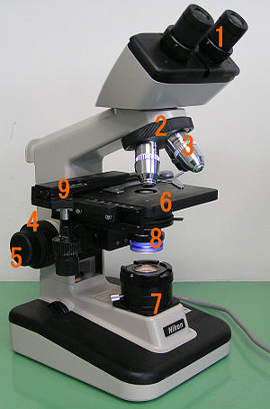
A microscope is a laboratory instrument used to examine objects that are too small to be seen by the naked eye. Microscopy is the science of investigating small objects and structures using a microscope. Microscopic means being invisible to the eye unless aided by a microscope.

<span class="mw-page-title-main">Transmission electron microscopy</span> Imaging and diffraction using electrons that pass through samples

Transmission electron microscopy (TEM) is a microscopy technique in which a beam of electrons is transmitted through a specimen to form an image. The specimen is most often an ultrathin section less than 100 nm thick or a suspension on a grid. An image is formed from the interaction of the electrons with the sample as the beam is transmitted through the specimen. The image is then magnified and focused onto an imaging device, such as a fluorescent screen, a layer of photographic film, or a detector such as a scintillator attached to a charge-coupled device or a direct electron detector.

<span class="mw-page-title-main">Diffraction-limited system</span> Optical system with resolution performance at the instruments theoretical limit

In optics, any optical instrument or system – a microscope, telescope, or camera – has a principal limit to its resolution due to the physics of diffraction. An optical instrument is said to be diffraction-limited if it has reached this limit of resolution performance. Other factors may affect an optical system's performance, such as lens imperfections or aberrations, but these are caused by errors in the manufacture or calculation of a lens, whereas the diffraction limit is the maximum resolution possible for a theoretically perfect, or ideal, optical system.

<span class="mw-page-title-main">Objective (optics)</span> Lens or mirror in optical instruments

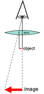
In optical engineering, an objective is an optical element that gathers light from an object being observed and focuses the light rays from it to produce a real image of the object. Objectives can be a single lens or mirror, or combinations of several optical elements. They are used in microscopes, binoculars, telescopes, cameras, slide projectors, CD players and many other optical instruments. Objectives are also called object lenses, object glasses, or objective glasses.

A total internal reflection fluorescence microscope (TIRFM) is a type of microscope with which a thin region of a specimen, usually less than 200 nanometers can be observed.

<span class="mw-page-title-main">Fluorescence microscope</span> Optical microscope that uses fluorescence and phosphorescence

A fluorescence microscope is an optical microscope that uses fluorescence instead of, or in addition to, scattering, reflection, and attenuation or absorption, to study the properties of organic or inorganic substances. "Fluorescence microscope" refers to any microscope that uses fluorescence to generate an image, whether it is a simple set up like an epifluorescence microscope or a more complicated design such as a confocal microscope, which uses optical sectioning to get better resolution of the fluorescence image.

<span class="mw-page-title-main">Confocal microscopy</span> Optical imaging technique

Confocal microscopy, most frequently confocal laser scanning microscopy (CLSM) or laser scanning confocal microscopy (LSCM), is an optical imaging technique for increasing optical resolution and contrast of a micrograph by means of using a spatial pinhole to block out-of-focus light in image formation. Capturing multiple two-dimensional images at different depths in a sample enables the reconstruction of three-dimensional structures within an object. This technique is used extensively in the scientific and industrial communities and typical applications are in life sciences, semiconductor inspection and materials science.

<span class="mw-page-title-main">Near-field scanning optical microscope</span>

Near-field scanning optical microscopy (NSOM) or scanning near-field optical microscopy (SNOM) is a microscopy technique for nanostructure investigation that breaks the far field resolution limit by exploiting the properties of evanescent waves. In SNOM, the excitation laser light is focused through an aperture with a diameter smaller than the excitation wavelength, resulting in an evanescent field on the far side of the aperture. When the sample is scanned at a small distance below the aperture, the optical resolution of transmitted or reflected light is limited only by the diameter of the aperture. In particular, lateral resolution of 6 nm and vertical resolution of 2–5 nm have been demonstrated.

<span class="mw-page-title-main">Dark-field microscopy</span> Laboratory technique

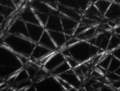
Dark-field microscopy describes microscopy methods, in both light and electron microscopy, which exclude the unscattered beam from the image. Consequently, the field around the specimen is generally dark.

<span class="mw-page-title-main">Bright-field microscopy</span> Optical microscopy illumination technique

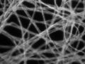
Bright-field microscopy (BF) is the simplest of all the optical microscopy illumination techniques. Sample illumination is transmitted white light, and contrast in the sample is caused by attenuation of the transmitted light in dense areas of the sample. Bright-field microscopy is the simplest of a range of techniques used for illumination of samples in light microscopes, and its simplicity makes it a popular technique. The typical appearance of a bright-field microscopy image is a dark sample on a bright background, hence the name.

Köhler illumination is a method of specimen illumination used for transmitted and reflected light optical microscopy. Köhler illumination acts to generate an even illumination of the sample and ensures that an image of the illumination source is not visible in the resulting image. Köhler illumination is the predominant technique for sample illumination in modern scientific light microscopy. It requires additional optical elements which are more expensive and may not be present in more basic light microscopes.

<span class="mw-page-title-main">Stereo microscope</span> Variant of an optical microscope

The stereo, stereoscopic or dissecting microscope is an optical microscope variant designed for low magnification observation of a sample, typically using light reflected from the surface of an object rather than transmitted through it. The instrument uses two separate optical paths with two objectives and eyepieces to provide slightly different viewing angles to the left and right eyes. This arrangement produces a three-dimensional visualization of the sample being examined. Stereomicroscopy overlaps macrophotography for recording and examining solid samples with complex surface topography, where a three-dimensional view is needed for analyzing the detail.

<span class="mw-page-title-main">Vertico spatially modulated illumination</span>

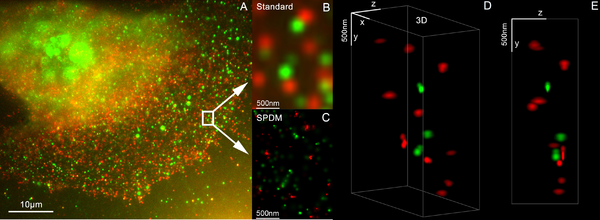
Vertico spatially modulated illumination (Vertico-SMI) is the fastest light microscope for the 3D analysis of complete cells in the nanometer range. It is based on two technologies developed in 1996, SMI and SPDM. The effective optical resolution of this optical nanoscope has reached the vicinity of 5 nm in 2D and 40 nm in 3D, greatly surpassing the λ/2 resolution limit applying to standard microscopy using transmission or reflection of natural light according to the Abbe resolution limit That limit had been determined by Ernst Abbe in 1873 and governs the achievable resolution limit of microscopes using conventional techniques.

<span class="mw-page-title-main">Optical sectioning</span> Imaging of focal planes within a thick sample

Optical sectioning is the process by which a suitably designed microscope can produce clear images of focal planes deep within a thick sample. This is used to reduce the need for thin sectioning using instruments such as the microtome. Many different techniques for optical sectioning are used and several microscopy techniques are specifically designed to improve the quality of optical sectioning.

Super-resolution microscopy is a series of techniques in optical microscopy that allow such images to have resolutions higher than those imposed by the diffraction limit, which is due to the diffraction of light. Super-resolution imaging techniques rely on the near-field or on the far-field. Among techniques that rely on the latter are those that improve the resolution only modestly beyond the diffraction-limit, such as confocal microscopy with closed pinhole or aided by computational methods such as deconvolution or detector-based pixel reassignment, the 4Pi microscope, and structured-illumination microscopy technologies such as SIM and SMI.

<span class="mw-page-title-main">Condenser (optics)</span> Type of optical lens

A condenser is an optical lens that renders a divergent light beam from a point light source into a parallel or converging beam to illuminate an object to be imaged.

<span class="mw-page-title-main">Light sheet fluorescence microscopy</span> Fluorescence microscopy technique

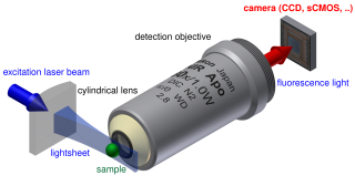
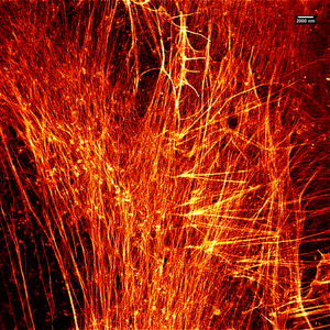
Light sheet fluorescence microscopy (LSFM) is a fluorescence microscopy technique with an intermediate-to-high optical resolution, but good optical sectioning capabilities and high speed. In contrast to epifluorescence microscopy only a thin slice of the sample is illuminated perpendicularly to the direction of observation. For illumination, a laser light-sheet is used, i.e. a laser beam which is focused only in one direction. A second method uses a circular beam scanned in one direction to create the lightsheet. As only the actually observed section is illuminated, this method reduces the photodamage and stress induced on a living sample. Also the good optical sectioning capability reduces the background signal and thus creates images with higher contrast, comparable to confocal microscopy. Because light sheet fluorescence microscopy scans samples by using a plane of light instead of a point, it can acquire images at speeds 100 to 1,000 times faster than those offered by point-scanning methods.

<span class="mw-page-title-main">Live-cell imaging</span> Study of living cells using time-lapse microscopy

Live-cell imaging is the study of living cells using time-lapse microscopy. It is used by scientists to obtain a better understanding of biological function through the study of cellular dynamics. Live-cell imaging was pioneered in the first decade of the 21st century. One of the first time-lapse microcinematographic films of cells ever made was made by Julius Ries, showing the fertilization and development of the sea urchin egg. Since then, several microscopy methods have been developed to study living cells in greater detail with less effort. A newer type of imaging using quantum dots have been used, as they are shown to be more stable. The development of holotomographic microscopy has disregarded phototoxicity and other staining-derived disadvantages by implementing digital staining based on cells’ refractive index.

Lattice light-sheet microscopy is a modified version of light sheet fluorescence microscopy that increases image acquisition speed while decreasing damage to cells caused by phototoxicity. This is achieved by using a structured light sheet to excite fluorescence in successive planes of a specimen, generating a time series of 3D images which can provide information about dynamic biological processes.

References

  1. JR Blueford. "Lesson 2 – Page 3, CLASSIFICATION OF MICROSCOPES". msnucleus.org. Archived from the original on 10 May 2016. Retrieved 15 January 2017.
  2. Trisha Knowledge Systems. The IIT Foundation Series - Physics Class 8, 2/e. Pearson Education India. p. 213. ISBN   978-81-317-6147-2.
  3. 1 2 Ian M. Watt (1997). The Principles and Practice of Electron Microscopy. Cambridge University Press. p. 6. ISBN   978-0-521-43591-8.
  4. "Buying a cheap microscope for home use" (PDF). Oxford University. Archived (PDF) from the original on 5 March 2016. Retrieved 5 November 2015.
  5. Kumar, Naresh; Weckhuysen, Bert M.; Wain, Andrew J.; Pollard, Andrew J. (April 2019). "Nanoscale chemical imaging using tip-enhanced Raman spectroscopy". Nature Protocols. 14 (4): 1169–1193. doi: 10.1038/s41596-019-0132-z . ISSN   1750-2799. PMID   30911174.
  6. Lee, Joonhee; Crampton, Kevin T.; Tallarida, Nicholas; Apkarian, V. Ara (April 2019). "Visualizing vibrational normal modes of a single molecule with atomically confined light". Nature. 568 (7750): 78–82. Bibcode:2019Natur.568...78L. doi:10.1038/s41586-019-1059-9. ISSN   1476-4687. PMID   30944493. S2CID   92998248.
  7. Aspden, Reuben S.; Gemmell, Nathan R.; Morris, Peter A.; Tasca, Daniel S.; Mertens, Lena; Tanner, Michael G.; Kirkwood, Robert A.; Ruggeri, Alessandro; Tosi, Alberto; Boyd, Robert W.; Buller, Gerald S.; Hadfield, Robert H.; Padgett, Miles J. (2015). "Photon-sparse microscopy: visible light imaging using infrared illumination" (PDF). Optica. 2 (12): 1049. Bibcode:2015Optic...2.1049A. doi: 10.1364/OPTICA.2.001049 . ISSN   2334-2536. Archived (PDF) from the original on 4 June 2016.
  8. Atti Della Fondazione Giorgio Ronchi E Contributi Dell'Istituto Nazionale Di Ottica, Volume 30, La Fondazione-1975, page 554
  9. Albert Van Helden; Sven Dupré; Rob van Gent (2010). The Origins of the Telescope. Amsterdam University Press. p. 24. ISBN   978-90-6984-615-6.
  10. William Rosenthal, Spectacles and Other Vision Aids: A History and Guide to Collecting, Norman Publishing, 1996, pp. 391–392
  11. 1 2 3 Raymond J. Seeger, Men of Physics: Galileo Galilei, His Life and His Works, Elsevier - 2016, page 24
  12. 1 2 3 J. William Rosenthal, Spectacles and Other Vision Aids: A History and Guide to Collecting, Norman Publishing, 1996, page 391
  13. Albert Van Helden; Sven Dupré; Rob van Gent (2010). The Origins of the Telescope. Amsterdam University Press. pp. 32–36, 43. ISBN   978-90-6984-615-6.
  14. Van Helden, p. 43
  15. Shmaefsky, Brian (2006) Biotechnology 101. Greenwood. p. 171. ISBN   0313335281.
  16. Note: stories vary, including Zacharias Janssen had the help of his father Hans Martens (or sometimes said to have been built entirely by his father). Zacharias' probable birth date of 1585 (Van Helden, p. 28) makes it unlikely he invented it in 1590 and the claim of invention is based on the testimony of Zacharias Janssen's son, Johannes Zachariassen, who may have fabricated the whole story (Van Helden, p. 43).
  17. Brian Shmaefsky, Biotechnology 101 - 2006, page 171
  18. "Who Invented the Microscope?". Live Science . 14 September 2013. Archived from the original on 3 February 2017. Retrieved 31 March 2017.
  19. Robert D. Huerta, Giants of Delft: Johannes Vermeer and the Natural Philosophers : the Parallel Search for Knowledge During the Age of Discovery, Bucknell University Press - 2003, page 126
  20. A. Mark Smith, From Sight to Light: The Passage from Ancient to Modern Optics, University of Chicago Press - 2014, page 387
  21. Daniel J. Boorstin, The Discoverers, Knopf Doubleday Publishing Group - 2011, page 327
  22. Gould, Stephen Jay (2000). "Chapter 2: The Sharp-Eyed Lynx, Outfoxed by Nature". The Lying Stones of Marrakech: Penultimate Reflections in Natural History . New York, N.Y: Harmony. ISBN   978-0-224-05044-9.
  23. "Il microscopio di Galileo" Archived 9 April 2008 at the Wayback Machine , Instituto e Museo di Storia della Scienza (in Italian)
  24. Gould, Stephen Jay (2000) The Lying Stones of Marrakech . Harmony Books. ISBN   0-609-60142-3.
  25. Riddell JL (1854). "On the binocular microscope". Q J Microsc Sci. 2: 18–24.
  26. Cassedy JH (1973). "John L. Riddell's Vibrio biceps: Two documents on American microscopy and cholera etiology 1849–59". J Hist Med. 28 (2): 101–108. doi:10.1093/jhmas/xxviii.2.101. PMID   4572620.
  27. "How to Use a Compound Microscope". Microscope.com. Retrieved 8 February 2023.
  28. Kenneth, Spring; Keller, H. Ernst; Davidson, Michael W. "Microscope objectives". Olympus Microscopy Resource Center. Archived from the original on 1 November 2008. Retrieved 29 October 2008.
  29. Pégard, Nicolas C.; Fleischer, Jason W. (1 May 2011). "Contrast Enhancement by Multi-Pass Phase-Conjugation Microscopy". CLEO:2011 - Laser Applications to Photonic Applications (2011), Paper CThW6. Optica Publishing Group: CThW6. doi:10.1364/CLEO_SI.2011.CThW6. ISBN   978-1-55752-910-7. S2CID   13366261.
  30. O1 Optical Microscopy Archived 24 January 2011 at the Wayback Machine By Katarina Logg. Chalmers Dept. Applied Physics. 20 January 2006
  31. "Long-focus microscope with camera adapter". macrolenses.de. Archived from the original on 3 October 2011.
  32. "Questar Maksutov microscope". company7.com. Archived from the original on 15 June 2011. Retrieved 11 July 2011.
  33. "FTA long-focus microscope". firsttenangstroms.com. Archived from the original on 26 February 2012. Retrieved 11 July 2011.
  34. Ollsson, Gustaf (2003). "Reticles". In Driggers, Ronald G. (ed.). Encyclopedia of Optical Engineering, Vol. 3. CRC Press. p. 2409. ISBN   978-0-824-74252-2.
  35. "Microscopy". Journal of the Royal Microscopical Society, Containing Its Transactions and Proceedings and a Summary of Current Researches Relating to Zoology and Botany (Principally Invertebrata and Cryptogamia), Microscopy, &c. 1906. p. 716. A discussion of Zeiss measuring microscopes.
  36. Linder, Courtney (22 November 2019). "If You've Ever Wanted a Smartphone Microscope, Now's Your Chance". Popular Mechanics. Retrieved 3 November 2020.
  37. Van Putten, E. G.; Akbulut, D.; Bertolotti, J.; Vos, W. L.; Lagendijk, A.; Mosk, A. P. (2011). "Scattering Lens Resolves Sub-100 nm Structures with Visible Light". Physical Review Letters. 106 (19): 193905. arXiv: 1103.3643 . Bibcode:2011PhRvL.106s3905V. doi:10.1103/PhysRevLett.106.193905. PMID   21668161. S2CID   15793849.
  38. Courjon, D.; Bulabois, J. (1979). "Real Time Holographic Microscopy Using a Peculiar Holographic Illuminating System and a Rotary Shearing Interferometer". Journal of Optics. 10 (3): 125. Bibcode:1979JOpt...10..125C. doi:10.1088/0150-536X/10/3/004.
  39. "Demonstration of a Low-Cost, Single-Molecule Capable, Multimode Optical Microscope". Archived from the original on 6 March 2009. Retrieved 25 February 2009.
  40. Ritter, Karl; Rising, Malin (8 October 2014). "2 Americans, 1 German win chemistry Nobel". AP News . Archived from the original on 11 October 2014. Retrieved 8 October 2014.
  41. Chang, Kenneth (8 October 2014). "2 Americans and a German Are Awarded Nobel Prize in Chemistry". New York Times . Archived from the original on 9 October 2014. Retrieved 8 October 2014.
  42. Heintzmann, Rainer (1999). Bigio, Irving J.; Schneckenburger, Herbert; Slavik, Jan; Svanberg, Katarina; Viallet, Pierre M. (eds.). Laterally modulated excitation microscopy: improvement of resolution by using a diffraction grating. Optical Biopsies and Microscopic Techniques III. Vol. 3568. pp. 185–196. doi:10.1117/12.336833. S2CID   128763403.
  43. Cremer, Christoph; Hausmann, Michael; Bradl, Joachim and Schneider, Bernhard "Wave field microscope with detection point spread function", U.S. patent 7,342,717 , priority date 10 July 1997
  44. Lemmer, P.; Gunkel, M.; Baddeley, D.; Kaufmann, R.; Urich, A.; Weiland, Y.; Reymann, J.; Müller, P.; Hausmann, M.; Cremer, C. (2008). "SPDM: light microscopy with single-molecule resolution at the nanoscale". Applied Physics B. 93 (1): 1–12. Bibcode:2008ApPhB..93....1L. doi:10.1007/s00340-008-3152-x. S2CID   13805053.
  45. Bradl, Joachim (1996). "Comparative study of three-dimensional localization accuracy in conventional, confocal laser scanning and axial tomographic fluorescence light microscopy". In Bigio, Irving J; Grundfest, Warren S; Schneckenburger, Herbert; Svanberg, Katarina; Viallet, Pierre M (eds.). Optical Biopsies and Microscopic Techniques. Optical Biopsies and Microscopic Techniques. Vol. 2926. pp. 201–206. doi:10.1117/12.260797. S2CID   55468495.
  46. Heintzmann, R.; Münch, H.; Cremer, C. (1997). "High-precision measurements in epifluorescent microscopy – simulation and experiment" (PDF). Cell Vision. 4: 252–253. Archived (PDF) from the original on 16 February 2016.
  47. Cremer, Christoph; Hausmann, Michael; Bradl, Joachim and Rinke, Bernd "Method and devices for measuring distances between object structures", U.S. patent 6,424,421 priority date 23 December 1996
  48. Manuel Gunkel; et al. (2009). "Dual color localization microscopy of cellular nanostructures" (PDF). Biotechnology Journal. 4 (6): 927–38. doi:10.1002/biot.200900005. PMID   19548231. S2CID   18162278. Archived (PDF) from the original on 3 May 2019.
  49. Kaufmann, R; Müller, P; Hildenbrand, G; Hausmann, M; Cremer, C; et al. (2011). "Analysis of Her2/neu membrane protein clusters in different types of breast cancer cells using localization microscopy". Journal of Microscopy. 242 (1): 46–54. CiteSeerX   10.1.1.665.3604 . doi:10.1111/j.1365-2818.2010.03436.x. PMID   21118230. S2CID   2119158.
  50. "German Future Prize for crossing Abbe's Limit". Archived from the original on 7 March 2009. Retrieved 24 February 2009.

Cited sources

Further reading