Apollo 8 was the first crewed spacecraft to leave low Earth orbit, and also the first human spaceflight to reach another astronomical object, namely the Moon, which the crew orbited without landing, and then departed safely back to Earth. These three astronauts—Frank Borman, James Lovell, and William Anders—were the first humans to witness and photograph an Earthrise.

Apollo 7 was the first crewed flight in NASA's Apollo program, and saw the resumption of human spaceflight by the agency after the fire that killed the three Apollo 1 astronauts during a launch rehearsal test on January 27, 1967. The Apollo 7 crew was commanded by Walter M. Schirra, with command module pilot Donn F. Eisele and lunar module pilot R. Walter Cunningham.

Apollo 9 was the third human spaceflight in NASA's Apollo program. Flown in low Earth orbit, it was the second crewed Apollo mission that the United States launched via a Saturn V rocket, and was the first flight of the full Apollo spacecraft: the command and service module (CSM) with the Lunar Module (LM). The mission was flown to qualify the LM for lunar orbit operations in preparation for the first Moon landing by demonstrating its descent and ascent propulsion systems, showing that its crew could fly it independently, then rendezvous and dock with the CSM again, as would be required for the first crewed lunar landing. Other objectives of the flight included firing the LM descent engine to propel the spacecraft stack as a backup mode, and use of the portable life support system backpack outside the LM cabin.

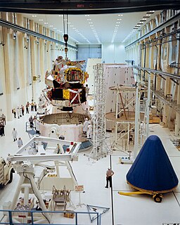
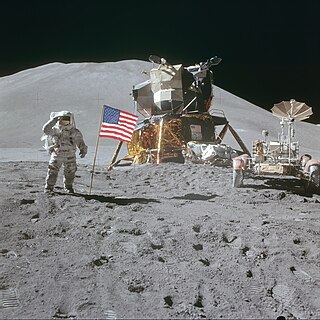
The Apollo Lunar Module, or simply Lunar Module, originally designated the Lunar Excursion Module (LEM), was the Lunar lander spacecraft that was flown between lunar orbit and the Moon's surface during the United States' Apollo program. It was the first crewed spacecraft to operate exclusively in the airless vacuum of space, and remains the only crewed vehicle to land anywhere beyond Earth.

The Apollo Guidance Computer (AGC) is a digital computer produced for the Apollo program that was installed on board each Apollo command module (CM) and Apollo Lunar Module (LM). The AGC provided computation and electronic interfaces for guidance, navigation, and control of the spacecraft.

Apollo 5, also known as AS-204, was the uncrewed first flight of the Apollo Lunar Module (LM) that would later carry astronauts to the surface of the Moon. The Saturn IB rocket bearing the LM lifted off from Cape Kennedy on January 22, 1968. The mission was successful, though due to programming problems an alternate mission to that originally planned was executed.
A guidance system is a virtual or physical device, or a group of devices implementing a controlling the movement of a ship, aircraft, missile, rocket, satellite, or any other moving object. Guidance is the process of calculating the changes in position, velocity, altitude, and/or rotation rates of a moving object required to follow a certain trajectory and/or altitude profile based on information about the object's state of motion.

AS-201, flown February 26, 1966, was the first uncrewed test flight of an entire production Block I Apollo command and service module and the Saturn IB launch vehicle. The spacecraft consisted of the second Block I command module and the first Block I service module. The suborbital flight was a partially successful demonstration of the service propulsion system and the reaction control systems of both modules, and successfully demonstrated the capability of the command module's heat shield to survive re-entry from low Earth orbit.

The Apollo spacecraft was composed of three parts designed to accomplish the American Apollo program's goal of landing astronauts on the Moon by the end of the 1960s and returning them safely to Earth. The expendable (single-use) spacecraft consisted of a combined command and service module (CSM) and an Apollo Lunar Module (LM). Two additional components complemented the spacecraft stack for space vehicle assembly: a spacecraft–LM adapter (SLA) designed to shield the LM from the aerodynamic stress of launch and to connect the CSM to the Saturn launch vehicle and a launch escape system (LES) to carry the crew in the command module safely away from the launch vehicle in the event of a launch emergency.

The Saturn V instrument unit is a ring-shaped structure fitted to the top of the Saturn V rocket's third stage (S-IVB) and the Saturn IB's second stage. It was immediately below the SLA (Spacecraft/Lunar Module Adapter) panels that contained the Apollo Lunar Module. The instrument unit contains the guidance system for the Saturn V rocket. Some of the electronics contained within the instrument unit are a digital computer, analog flight control computer, emergency detection system, inertial guidance platform, control accelerometers, and control rate gyros. The instrument unit (IU) for Saturn V was designed by NASA at Marshall Space Flight Center (MSFC) and was developed from the Saturn I IU. NASA's contractor to manufacture the Saturn V Instrument Unit was International Business Machines (IBM).

The Apollo command and service module (CSM) was one of two principal components of the United States Apollo spacecraft, used for the Apollo program, which landed astronauts on the Moon between 1969 and 1972. The CSM functioned as a mother ship, which carried a crew of three astronauts and the second Apollo spacecraft, the Apollo Lunar Module, to lunar orbit, and brought the astronauts back to Earth. It consisted of two parts: the conical command module, a cabin that housed the crew and carried equipment needed for atmospheric reentry and splashdown; and the cylindrical service module which provided propulsion, electrical power and storage for various consumables required during a mission. An umbilical connection transferred power and consumables between the two modules. Just before reentry of the command module on the return home, the umbilical connection was severed and the service module was cast off and allowed to burn up in the atmosphere.

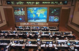
Flight controllers are personnel who aid space flight by working in such Mission Control Centers as NASA's Mission Control Center or ESA's European Space Operations Centre. Flight controllers work at computer consoles and use telemetry to monitor various technical aspects of a space mission in real time. Each controller is an expert in a specific area and constantly communicates with additional experts in the "back room". The flight director, who leads the flight controllers, monitors the activities of a team of flight controllers, and has overall responsibility for success and safety.

Lunar escape systems (LESS) were a series of emergency vehicles designed for never-flown long-duration Apollo missions. Because these missions were even more hypothetical than the planned cancelled Apollo missions, the designs were never constructed. This concept was an outgrowth of the Lunar Flying Vehicle designed by Bell Aerospace.

John Royer "Jack" Garman was a computer engineer, former senior NASA executive and noted key figure of the Apollo 11 lunar landing. As a young specialist on duty during the final descent stage on 20 July 1969 he dealt with a series of computer alarms which could have caused the mission to be aborted.

The Apollo Abort Guidance System was a backup computer system providing an abort capability in the event of failure of the Lunar Module's primary guidance system during descent, ascent or rendezvous. As an abort system, it did not support guidance for a lunar landing.

Transposition, docking, and extraction was a maneuver performed during Apollo lunar landing missions from 1969 to 1972, to withdraw the Apollo Lunar Module (LM) from its adapter housing which secured it to the Saturn V launch vehicle upper stage and protected it from the aerodynamic stresses of launch. The maneuver involved the command module pilot separating the Apollo Command and Service Module (CSM) from the adapter, turning the CSM around, and docking its nose to the Lunar Module, then pulling the combined spacecraft away from the upper stage. It was performed shortly after the trans-lunar injection maneuver that placed the Apollo spacecraft on a three-day trajectory to the Moon. The docking created a continuous, pressurized tunnel which permitted the astronauts to transfer internally between the CSM and the LM.
Albert L. Hopkins Jr. was an American computer designer. He worked at the US MIT Instrumentation Laboratory during the development of the Apollo Guidance, Navigation, and Control System, or the GN&C. The system was designed in two forms, one for the command module and one for the lunar module. The CM version included an optical system with an integrated scanning telescope and sextant for erecting and correcting the inertial platform. Albert Hopkins received a Ph.D. from Harvard University under Howard Aiken, he then joined the MIT Instrumentation Lab where he was Assistant Director; together with Ramon Alonso, and Hugh Blair-Smith he was a member of the group that designed the computer, designated AGC for Apollo Guidance Computer, identical in the CM and LM.

An inertial navigation system (INS) is a navigation device that uses a computer, motion sensors (accelerometers) and rotation sensors (gyroscopes) to continuously calculate by dead reckoning the position, the orientation, and the velocity of a moving object without the need for external references. Often the inertial sensors are supplemented by a barometric altimeter and sometimes by magnetic sensors (magnetometers) and/or speed measuring devices. INSs are used on mobile robots and on vehicles such as ships, aircraft, submarines, guided missiles, and spacecraft. Other terms used to refer to inertial navigation systems or closely related devices include inertial guidance system, inertial instrument, inertial measurement unit (IMU) and many other variations. Older INS systems generally used an inertial platform as their mounting point to the vehicle and the terms are sometimes considered synonymous.

The Unified S-band (USB) system is a tracking and communication system developed for the Apollo program by NASA and the Jet Propulsion Laboratory (JPL). It operated in the S band portion of the microwave spectrum, unifying voice communications, television, telemetry, command, tracking and ranging into a single system to save size and weight and simplify operations. The USB ground network was managed by the Goddard Space Flight Center (GSFC). Commercial contractors included Collins Radio, Blaw-Knox, Motorola and Energy Systems.
Don Eyles is a retired computer scientist who worked on the computer systems in the Apollo Lunar Module vehicle. As a young engineer during the lunar landing on Lunar Module Eagle on 20 July 1969 he assisted with a series of computer alarms caused by data overflow from the radar, which could have caused the mission to be aborted.


