Saturn V instrument unit

Last updated
Diagram of Saturn V instrument unit Saturn IB and V Instrument Unit.jpg
Diagram of Saturn V instrument unit

The Saturn V instrument unit is a ring-shaped structure fitted to the top of the Saturn V rocket's third stage (S-IVB) and the Saturn IB's second stage (also an S-IVB). It was immediately below the SLA (Spacecraft/Lunar Module Adapter) panels that contained the Apollo Lunar Module. The instrument unit contains the guidance system for the Saturn V rocket. Some of the electronics contained within the instrument unit are a digital computer, analog flight control computer, emergency detection system, inertial guidance platform, control accelerometers, and control rate gyros. The instrument unit (IU) for Saturn V was designed by NASA at Marshall Space Flight Center (MSFC) and was developed from the Saturn I IU. [1] NASA's contractor to manufacture the Saturn V Instrument Unit was International Business Machines (IBM). [2]

Contents

One of the unused instrument units is on display at the Steven F. Udvar-Hazy Center in Chantilly, Virginia. The plaque for the unit has the following inscription: [3] [4]

The Saturn V rocket, which sent astronauts to the Moon, used inertial guidance, a self-contained system that guided the rocket's trajectory. The rocket booster had a guidance system separate from those on the command and lunar modules. It was contained in an instrument unit like this one, a ring located between the rocket's third stage and the command and lunar modules. The ring contained the basic guidance system components—a stable platform, accelerometers, a digital computer, and control electronics—as well as radar, telemetry, and other units.

The instrument unit's stable platform was based on an experimental unit for the German V-2 rocket of World War II. The Bendix Corporation produced the platform, while IBM designed and built the unit's digital computer.

View of IU-514 from the floor of UHC Instrument Unit 514 (IMGP3463mod).jpg
View of IU-514 from the floor of UHC
Instrument unit no. 514 at National Air & Space Museum, Udvar-Hazy Center, Dulles, Virginia; the nose of Space Shuttle Enterprise is visible at left. Instrument Unit 514 (IMGP3476mod).jpg
Instrument unit no. 514 at National Air & Space Museum, Udvar-Hazy Center, Dulles, Virginia; the nose of Space Shuttle Enterprise is visible at left.

Specifications

Mission history

There was no instrument unit for Saturn I Block I boosters (SA-1 to SA-4). Guidance and control equipment was carried in canisters on top of the S-I first stage, and included the ST-90 stabilized platform, made by Ford Instrument Company and used in the Jupiter missile. [5]

The IU made its debut with SA-5, the first Saturn I Block II launch. The first version of the IU was 154 inches (3,900 mm) in diameter and 58 inches (1,500 mm) high, and was both designed and built by MSFC. Guidance, telemetry, tracking and power components were contained in four pressurized, cylindrical containers attached like spokes to a central hub. [6]

MSFC flew version 2 of the IU on SA-8, 9 and 10. Version 2 was the same diameter as version 1, but only 34 inches (860 mm) high. Instead of pressurized containers, the components were hung on the inside of the cylindrical wall, achieving a reduction in weight. [7]

The last version, number 3, was 260 inches (6,600 mm) in diameter and 36 inches (910 mm) tall. It was designed by MSFC but manufactured by IBM in their factory at Huntsville, and flew on all Saturn IB and Saturn V launches. This is the version that is on display in Washington, Huntsville, Houston, and the Apollo/Saturn V Center.

Saturn instrument unit launch history [8] [9] [10] [11]
ProgramVehicleMissionLaunch datePadIU versionIU
Saturn I SA-1 SA-1 27 Oct 196134-
Saturn ISA-2 SA-2 25 Apr 196234-
Saturn ISA-3 SA-3 16 Nov 196234-
Saturn ISA-4 SA-4 28 Mar 196334-
Saturn ISA-5 SA-5 29 Jan 196437B1S-IU-5
Saturn ISA-6 AS-101 28 May 196437B1S-IU-6
Saturn ISA-7 AS-102 18 Sep 196437B1S-IU-7
Saturn ISA-9 AS-103 16 Feb 196537B2S-IU-9
Saturn ISA-8 AS-104 25 May 196537B2S-IU-8
Saturn ISA-10 AS-105 30 Jul 196537B2S-IU-10
Saturn IB SA-201 AS-201 26 Feb 1966343S-IU-201
Saturn IBSA-203 AS-203 5 Jul 196637B3S-IU-203
Saturn IBSA-202 AS-202 25 Aug 1966343S-IU-202
Saturn V SA-501 Apollo 4 9 Nov 196739A3S-IU-501
Saturn IBSA-204 Apollo 5 22 Jan 196837B3S-IU-204
Saturn VSA-502 Apollo 6 4 Apr 196839A3S-IU-502
Saturn IBSA-205 Apollo 7 11 Oct 1968343S-IU-205
Saturn VSA-503 Apollo 8 21 Dec 196839A3S-IU-503
Saturn VSA-504 Apollo 9 3 Mar 196939A3S-IU-504
Saturn VSA-505 Apollo 10 18 May 196939B3S-IU-505
Saturn VSA-506 Apollo 11 16 Jul 196939A3S-IU-506
Saturn VSA-507 Apollo 12 14 Nov 196939A3S-IU-507
Saturn VSA-508 Apollo 13 11 Apr 197039A3S-IU-508
Saturn VSA-509 Apollo 14 31 Jan 197139A3S-IU-509
Saturn VSA-510 Apollo 15 26 Jul 197139A3S-IU-510
Saturn VSA-511 Apollo 16 16 Apr 197239A3S-IU-511
Saturn VSA-512 Apollo 17 7 Dec 197239A3S-IU-512
Saturn VSA-513 Skylab 1 14 May 197339A3S-IU-513
Saturn IBSA-206 Skylab 2 25 May 197339B3S-IU-206
Saturn IBSA-207 Skylab 3 28 Jul 197339B3S-IU-207
Saturn IBSA-208 Skylab 4 16 Nov 197339B3S-IU-208
Saturn IBSA-210 ASTP 15 Jul 197539B3S-IU-210
Saturn IBSA-209 Skylab Rescue UnflownS-IU-209
Saturn IBSA-211UnassignedUnflownS-IU-211
Saturn IBSA-212UnassignedUnflownS-IU-212
Saturn VSA-514 Apollo 18 UnflownS-IU-514
Saturn VSA-515 Apollo 19 UnflownS-IU-515
Saturn VSA-500-FGround Test VehicleS-IU-500F(200F)
Saturn VSA-500-DGround Test VehicleS-IU-D

Mission profile

Saturn Apollo flight profiles varied considerably by mission. [12] [13] [14] All missions began, however, with liftoff under power of the first stage. To more smoothly control engine ignition, thrust buildup and liftoff of the vehicle, restraining arms provided support and hold down at four points around the base of the S-IC stage. A gradual controlled release was accomplished during the first six inches of vertical motion.

After clearing the launch tower, a flight program stored in the launch vehicle digital computer (LVDC) commanded a roll of the vehicle to orient it so that the subsequent pitch maneuver pointed the vehicle in the desired azimuth. The roll and pitch commands were controlled by the stored program, and were not affected by navigation measurements. Until the end of the S-IC burn, guidance commands were functions only of time.

First stage cutoff and stage separation were commanded when the IU received a signal that the tank's fuel level had reached a predetermined point. Guidance during the second and third stage burns depended both on time and navigation measurements, in order to achieve the target orbit using the minimum fuel.

Second stage engine cutoff was commanded by the IU at a pre-determined fuel level, and the stage was separated. By this time, the vehicle had reached its approximate orbital altitude, and the third stage burn was just long enough to reach a circular parking orbit.

During crewed Apollo missions, the vehicle coasted in Earth orbit for 2-4 passes as the crew performed checks of systems status and other tasks, and as ground stations tracked the vehicle. During the hour and a half after launch, tracking stations around the world had refined estimates of the vehicle's position and velocity, collectively known as its state vector. The latest estimates were relayed to the guidance systems in the IU, and to the Command Module Computer in the spacecraft. When the Moon, Earth, and vehicle were in the optimum geometrical configuration, the third stage was reignited to put the vehicle into a translunar orbit. For Apollo 15, for example, this burn lasted 5 minutes 55 seconds.

After translunar injection came the maneuver called transposition, docking, and extraction. This was under crew control, but the IU held the S-IVB/IU vehicle steady while the Command/Service Module (CSM) first separated from the vehicle, rotated 180 degrees, and returned to dock with the Lunar Module (LM). When the CSM and LM had "hard docked" (connected by a dozen latches), the rearranged spacecraft separated from the S-IVB/IU.

The last function of the IU was to command the very small maneuver necessary to keep the S-IVB/IU out of the way of the spacecraft. On some missions the S-IVB/IU went into high Earth or Solar orbit, while on others it was crashed into the Moon; seismometers were left on the Moon during Apollo 11, 12, 14, 15, and 16, and the S-IVB/IUs of Apollo 13, 14, 15, 16, and 17 were directed to crash. These impacts provided impulses that were recorded by the seismometer network to yield information about the geological structure of the Moon.

Subsystems

Interior of IU-514, with components labeled Saturn IU Mk12cyl3mod2Crop25pct.jpg
Interior of IU-514, with components labeled
Diagram of exterior of IU-514 IUExteriorMk2.jpg
Diagram of exterior of IU-514

The IU consists of six subsystems: structure, guidance and control, environmental control, emergency detection, radio communications (for telemetry, tracking, and command), and power.

Structure

The basic IU structure is a short cylinder, 36 inches high and 260 inches (6,600 mm) in diameter, fabricated of an aluminum alloy honeycomb sandwich material 0.95 inches (24 mm) thick. The cylinder is manufactured in three 120-degree segments, which are joined by splice plates into an integral structure. The top and bottom edges are made from extruded aluminum channels bonded to the honeycomb sandwich. This type of construction was selected for its high strength to weight ratio, acoustical insulation, and thermal conductivity properties. The IU supported the components mounted on its inner wall and the weight of the Apollo spacecraft above (the Lunar Module, the Command Module, the Service Module, and the Launch Escape Tower). To facilitate handling the IU before it was assembled into the Saturn, the fore and aft protective rings, 6 inches tall and painted blue, were bolted to the top and bottom channels. These were removed in the course of stacking the IU into the Saturn vehicle. The structure was manufactured by North American Rockwell in Tulsa, Oklahoma. Edward A. Beasley was the I.U. Program Manager.

The IU is divided into 24 locations, which are marked on the interior by numbers 1–24 on the aluminum surface just above the blue flange.

Guidance and control

Drawing on the ST-124-M3 inertial platform ST-124gimbals.jpg
Drawing on the ST-124-M3 inertial platform

The Saturn V launch vehicle was guided by navigation, guidance, and control equipment located in the IU. A space stabilized platform (the ST-124-M3 inertial platform at location 21) measured acceleration and attitude. A launch vehicle digital computer (LVDC at location 19) solved guidance equations, and an analog flight control computer (location 16) issued commands to steer the vehicle.

The attitude of the vehicle was defined in terms of three axes:

The ST-124-M3 inertial platform contains three gimbals: the outer gimbal (which can rotate 360° about the roll or X axis of the vehicle), the middle gimbal (which can rotate ±45° about the yaw or Z axis of the vehicle), and the inner or inertial gimbal (which can rotate 360° about the pitch or Y axis of the vehicle). The inner gimbal is a platform to which are fixed several components:

The angular positions of gimbals on their axes were measured by resolvers, which sent their signals to the Launch Vehicle Data Adaptor (LVDA). The LVDA was the input/output device for the LVDC. It performed the necessary processing of signals to make these signals acceptable to the LVDC.

The instantaneous attitude of the vehicle was compared with the desired vehicle attitude in the LVDC. Attitude correction signals from the LVDC were converted into control commands by the flight control computer. The required thrust direction was obtained by gimbaling the engines in the propelling stage to change the thrust direction of the vehicle. Gimbaling of these engines was accomplished through hydraulic actuators. In the first and second stages (S-IC and S-II), the four outboard engines were gimbaled to control roll, pitch, and yaw. Since the third (S-IVB) stage has only one engine, an auxiliary propulsion system was used for roll control during powered flight. The auxiliary propulsion system provides complete attitude control during coast flight of the S-IVB/IU stage.

Environmental control

The environmental control system (ECS) maintains an acceptable operating environment for the IU equipment during preflight and flight operations. The ECS is composed of the following:

Thermal conditioning

Thermal conditioning panels, also called cold plates, were located in both the IU and S-IVB stage (up to sixteen in each stage). Each cold plate contains tapped bolt holes in a grid pattern which provides flexibility of component mounting.

The cooling fluid circulated through the TCS was a mixture of 60 percent methanol and 40 percent demineralized water by weight. Each cold plate was capable of dissipating at least 420 watts.

During flight, heat generated by equipment mounted on the cold plates was dissipated to space by a sublimation heat exchanger. Water from a reservoir (water accumulator) was exposed to the low temperature and pressure environment of space, where it first freezes and then sublimates, taking heat from the heat exchanger and transferring it to the water molecules which escape to space in gaseous state. Water/methanol was cooled by circulation through the heat exchanger.

Preflight air/GN2 purge system

Before flight, ground support equipment (GSE) supplies cooled, filtered ventilating air to the IU, entering via the large duct in the middle of the umbilical panel (location 7), and branching into two ducts at the top that are carried around the IU in the cable rack. Downward pointing vents from these ducts release ventilating air to the interior of the IU. During fueling, gaseous nitrogen was supplied instead of air, to purge any propellant gases that might otherwise accumulate in the IU.

Gas bearing supply

To reduce errors in sensing attitude and velocity, designers cut friction to a minimum in the platform gyros and accelerometers by floating the bearings on a thin film of dry nitrogen. The nitrogen was supplied from a sphere holding 2 cu ft (56.6 L) of gas at 3,000 psig (pounds per square inch gauge, i.e. psi above one atmosphere) (20,7 MPa). This sphere is 21 inches (0,53 m) in diameter and is mounted at location 22, to the left of the ST-124-M3. Gas from the supply sphere passes through a filter, a pressure regulator, and a heat exchanger before flowing through the bearings in the stable platform.

Hazardous gas detection

The hazardous gas detection system monitors the presence of hazardous gases in the IU and S-IVB stage forward compartments during vehicle fueling. Gas was sampled at four locations: between panels 1 and 2, 7 and 8, 13 and 14, and 19 and 20. Tubes lead from these locations to location 7, where they were connected to ground support equipment (external to the IU) which can detect hazardous gases.

Emergency detection

The emergency detection system (EDS) sensed initial development of conditions in the flight vehicle during the boost phases of flight which could cause vehicle failure. The EDS reacted to these emergency situations in one of two ways. If breakup of the vehicle were imminent, an automatic abort sequence would be initiated. If, however, the emergency condition were developing slowly enough or were of such a nature that the flight crew can evaluate it and take action, only visual indications were provided to the flight crew. Once an abort sequence had been initiated, either automatically or manually, it was irrevocable and ran to completion.

The EDS was distributed throughout the vehicle and includes some components in the IU. There were nine EDS rate gyros installed at location 15 in the IU. Three gyros monitored each of the three axes (pitch, roll and yaw), providing triple redundancy. The control signal processor (location 15) provided power to and received inputs from the nine EDS rate gyros. These inputs were processed and sent to the EDS distributor (location 14) and to the flight control computer (location 16). The EDS distributor served as a junction box and switching device to furnish the spacecraft display panels with emergency signals if emergency conditions existed. It also contained relay and diode logic for the automatic abort sequence. An electronic timer (location 17) was activated at liftoff and 30 seconds later energized relays in the EDS distributor which allowed multiple engine shutdown. This function was inhibited during the first 30 seconds of launch, to preclude the vehicle falling back into the launch area. While the automatic abort was inhibited, the flight crew could initiate a manual abort if an angular-overrate or two-engine-out condition arose.

Radio communications

The IU communicated by radio continually to ground for several purposes. The measurement and telemetry system communicated data about internal processes and conditions on the Saturn V. The tracking system communicated data used by the Mission Ground Station (MGS) to determine vehicle location. The radio command system allowed the MGS to send commands up to the IU.

Measuring and telemetry

Approximately 200 parameters were measured on the IU and transmitted to the ground, in order to

  • Assist in the checkout of the launch vehicle prior to launch,
  • Determine vehicle condition and to verify received commands during flight, and
  • Facilitate postflight analysis of the mission.

Parameters measured include acceleration, angular velocity, flow rate [ which? ], position, pressure, temperature, voltage, current, frequency, and others. Sensor signals were conditioned by amplifiers or converters located in measuring racks. There are four measuring racks in the IU at locations 1, 9, and 15 and twenty signal conditioning modules in each.[ clarification needed ] Conditioned signals were routed to their assigned telemetry channel by the measuring distributor at location 10. There were two telemetry links. In order for the two IU telemetry links to handle approximately 200 separate measurements, these links must be shared. Both frequency sharing and time sharing multiplexing techniques were used to accomplish this. The two modulation techniques used were pulse-code modulation/frequency modulation (PCM/FM) and frequency modulation/frequency modulation (FM/FM).

Two Model 270 time sharing multiplexers (MUX-270) were used in the IU telemetry system, mounted at locations 9 and 10. Each one operates as a 30×120 multiplexer (30 primary channels, each sampled 120 times per second) with provisions for submultiplexing individual primary channels to form 10 subchannels each sampled at 12 times per second. Outputs from the MUX-270 go to the PCM/DDAS assembly model 301 at location 12, which in turn drives the 245.3 MHz PCM VHF transmitter.

The FM/FM signals were carried in 28 subcarrier channels and transmitted by a 250.7 MHz FM transmitter.

Both the FM/FM and the PCM/FM channels were coupled to the two telemetry antennas on opposite sides of the IU outside locations 10 and 22.

Tracking

C-band radar transponders carried by the IU provided tracking data to the ground which were used to determine the vehicle's trajectory. The transponder received coded or single pulse interrogation from ground stations and transmitted a single-pulse reply in the same frequency band (5.4 to 5.9 GHz). A common antenna was used for receiving and transmitting. The C-band transponder antennas are outside locations 11 and 23, immediately below CCS PCM omni receive antennas.

Radio command

The command communications system (CCS) provided for digital data transmission from ground stations to the LVDC. This communications link was used to update guidance information or command certain other functions through the LVDC. Command data originated in the Mission Control Center, Houston, and was sent to remote stations for transmission to the launch vehicle. Command messages were transmitted from the ground at 2101.8 MHz. The received message was passed to the command decoder (location 18), where it was checked for authenticity before being passed to the LVDC. Verification of message receipt was accomplished through the IU PCM telemetry system. The CCS system used five antennas:

  • A single directional antenna outside location 3–4,
  • Two omni transmit antennas outside locations 11 and 23, and
  • Two omni receive antennas outside locations 12 and 24.

Power

Power during flight originated with four silver-zinc batteries with a nominal voltage of 28±2 vdc. Battery D10 sat on a shelf at location 5, batteries D30 and D40 were on shelves in location 4, and battery D20 was at location 24. Two power supplies converted the unregulated battery power to regulated 56 vdc and 5 vdc. The 56 vdc power supply was at location 1 and provided power to the ST-124-M3 platform electronic assembly and the accelerometer signal conditioner. The 5 vdc power supply at location 12 provided 5 ±.005 vdc to the IU measuring system.

These images show the development of the IU. The first four Saturn launches did not have an IU, but used guidance, telemetry and other equipment installed on top of the first stage.

The first IU flew on the fifth Saturn launch, SA-5, and was 12 feet 10 inches (3.91 m) in diameter and 4 feet 10 inches (1.47 m) high. The components it carried were in pressurized containers. This version flew on SA-5, SA-6 and SA-7. The IU carried by missions SA-8, -9, and -10 was only 2 feet 10 inches (0.86 m) high, and was not pressurized. [16]

With the Saturn IB and Saturn V launches, a third version was used, 21.6 feet (6.6 m) in diameter and 3 feet (0.91 m) high. Comparison of these photographs of the instrument unit shows that the configuration of components carried by this version changed, depending on the mission. Some equipment was deleted (e.g., the Azusa tracking system was deleted from later IUs), some equipment was added (e.g., a fourth battery for longer missions), and other components were moved around.

These images also show that some components (e.g., batteries, the ST-124 inertial platform) were installed in the IU after it had been stacked in the VAB on top of the S-IVB third stage.

Related Research Articles

<span class="mw-page-title-main">Marshall Space Flight Center</span> Rocketry and spacecraft propulsion research center

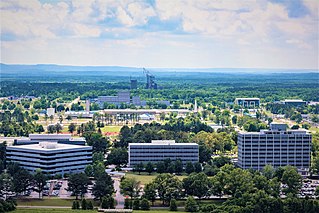
The George C. Marshall Space Flight Center (MSFC), located in Redstone Arsenal, Alabama, is the U.S. government's civilian rocketry and spacecraft propulsion research center. As the largest NASA center, MSFC's first mission was developing the Saturn launch vehicles for the Apollo program. Marshall has been the lead center for the Space Shuttle main propulsion and external tank; payloads and related crew training; International Space Station (ISS) design and assembly; computers, networks, and information management; and the Space Launch System. Located on the Redstone Arsenal near Huntsville, MSFC is named in honor of General of the Army George C. Marshall.

<span class="mw-page-title-main">Apollo 4</span> First test flight of the Apollo Saturn V rocket

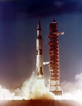
Apollo 4, also known as SA-501, was the uncrewed first test flight of the Saturn V launch vehicle, the rocket that eventually took astronauts to the Moon. The space vehicle was assembled in the Vehicle Assembly Building, and was the first to be launched from Kennedy Space Center (KSC) in Florida, ascending from Launch Complex 39, where facilities built specially for the Saturn V had been constructed.

<span class="mw-page-title-main">Apollo 5</span> Uncrewed first test flight of the Apollo Lunar Module

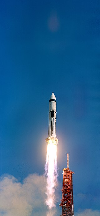
Apollo 5, also known as AS-204, was the uncrewed first flight of the Apollo Lunar Module (LM) that would later carry astronauts to the surface of the Moon. The Saturn IB rocket bearing the LM lifted off from Cape Kennedy on January 22, 1968. The mission was successful, though due to programming problems an alternate mission to that originally planned was executed.

<span class="mw-page-title-main">Apollo 6</span> Second test flight of the Apollo Saturn V rocket

Apollo 6, also known as AS-502, was the third and final uncrewed flight in the United States' Apollo Program and the second test of the Saturn V launch vehicle. It qualified the Saturn V for use on crewed missions, and it was used beginning with Apollo 8 in December 1968.

<span class="mw-page-title-main">AS-201</span> 1966 uncrewed, suborbital test flight within the Apollo program

AS-201, flown February 26, 1966, was the first uncrewed test flight of an entire production Block I Apollo command and service module and the Saturn IB launch vehicle. The spacecraft consisted of the second Block I command module and the first Block I service module. The suborbital flight was a partially successful demonstration of the service propulsion system and the reaction control systems of both modules, and successfully demonstrated the capability of the command module's heat shield to survive re-entry from low Earth orbit.

<span class="mw-page-title-main">AS-203</span> Uncrewed flight of the Saturn IB rocket, July 5, 1966

AS-203 was an uncrewed flight of the Saturn IB rocket on July 5, 1966. It carried no command and service module, as its purpose was to verify the design of the S-IVB rocket stage restart capability that would later be used in the Apollo program to boost astronauts from Earth orbit to a trajectory towards the Moon. It achieved its objectives, but the stage was inadvertently destroyed after four orbits.

<span class="mw-page-title-main">AS-202</span> Uncrewed test flight of the Apollo Program

AS-202 was the second uncrewed, suborbital test flight of a production Block I Apollo command and service module launched with the Saturn IB launch vehicle. It was launched on August 25, 1966, and was the first flight which included the spacecraft guidance, navigation control system and fuel cells. The success of this flight enabled the Apollo program to judge the Block I spacecraft and Saturn IB ready to carry men into orbit on the next mission, AS-204.

<span class="mw-page-title-main">Saturn I SA-3</span> Third flight of the Saturn I

Saturn-Apollo 3 (SA-3) was the third flight of the Saturn I launch vehicle, the second flight of Project Highwater, and part of the American Apollo program. The rocket was launched on November 16, 1962, from Cape Canaveral, Florida.

<span class="mw-page-title-main">AS-101</span> 1964 Apollo Program test flight

AS-101 was the sixth flight of the Saturn I launch vehicle, which carried the first boilerplate Apollo spacecraft into low Earth orbit. The test took place on May 28, 1964, lasting for four orbits. The spacecraft and its upper stage completed a total of 54 orbits before reentering the atmosphere and crashing in the Pacific Ocean on June 1, 1964.

<span class="mw-page-title-main">AS-102</span>

AS-102 was the seventh flight of the Saturn I launch vehicle, which carried the boilerplate Apollo spacecraft BP-15 into low Earth orbit. The test took place on September 18, 1964, lasting for five orbits. The spacecraft and its upper stage completed 59 orbits before reentering the atmosphere and crashing in the Indian Ocean on September 22, 1964.

<span class="mw-page-title-main">Apollo (spacecraft)</span> Saturn V-launched payload that took men to the Moon

The Apollo spacecraft was composed of three parts designed to accomplish the American Apollo program's goal of landing astronauts on the Moon by the end of the 1960s and returning them safely to Earth. The expendable (single-use) spacecraft consisted of a combined command and service module (CSM) and an Apollo Lunar Module (LM). Two additional components complemented the spacecraft stack for space vehicle assembly: a spacecraft–LM adapter (SLA) designed to shield the LM from the aerodynamic stress of launch and to connect the CSM to the Saturn launch vehicle and a launch escape system (LES) to carry the crew in the command module safely away from the launch vehicle in the event of a launch emergency.

<span class="mw-page-title-main">Saturn IB</span> American rocket used in the Apollo program during the 1960s and 70s

The Saturn IB(also known as the uprated Saturn I) was an American launch vehicle commissioned by the National Aeronautics and Space Administration (NASA) for the Apollo program. It uprated the Saturn I by replacing the S-IV second stage, with the S-IVB. The S-IB first stage also increased the S-I baseline's thrust from 1,500,000 pounds-force (6,700,000 N) to 1,600,000 pounds-force (7,100,000 N) and propellant load by 3.1%. This increased the Saturn I's low Earth orbit payload capability from 20,000 pounds (9,100 kg) to 46,000 pounds (21,000 kg), enough for early flight tests of a half-fueled Apollo command and service module (CSM) or a fully fueled Apollo Lunar Module (LM), before the larger Saturn V needed for lunar flight was ready.

The Saturn I was a rocket designed as the United States' first medium lift launch vehicle for up to 20,000-pound (9,100 kg) low Earth orbit payloads. The rocket's first stage was built as a cluster of propellant tanks engineered from older rocket tank designs, leading critics to jokingly refer to it as "Cluster's Last Stand". Its development was taken over from the Advanced Research Projects Agency in 1958 by the newly formed civilian NASA. Its design proved sound and flexible. It was successful in initiating the development of liquid hydrogen-fueled rocket propulsion, launching the Pegasus satellites, and flight verification of the Apollo command and service module launch phase aerodynamics. Ten Saturn I rockets were flown before it was replaced by the heavy lift derivative Saturn IB, which used a larger, higher total impulse second stage and an improved guidance and control system. It also led the way to development of the super-heavy lift Saturn V which carried the first men to landings on the Moon in the Apollo program.

<span class="mw-page-title-main">Rocketdyne J-2</span> Rocket engine

The J-2, commonly known as Rocketdyne J-2, was a liquid-fuel cryogenic rocket engine used on NASA's Saturn IB and Saturn V launch vehicles. Built in the United States by Rocketdyne, the J-2 burned cryogenic liquid hydrogen (LH2) and liquid oxygen (LOX) propellants, with each engine producing 1,033.1 kN (232,250 lbf) of thrust in vacuum. The engine's preliminary design dates back to recommendations of the 1959 Silverstein Committee. Rocketdyne won approval to develop the J-2 in June 1960 and the first flight, AS-201, occurred on 26 February 1966. The J-2 underwent several minor upgrades over its operational history to improve the engine's performance, with two major upgrade programs, the de Laval nozzle-type J-2S and aerospike-type J-2T, which were cancelled after the conclusion of the Apollo program.

Several planned missions of the Apollo crewed Moon landing program of the 1960s and 1970s were canceled, for reasons which included changes in technical direction, the Apollo 1 fire, hardware delays, and budget limitations. After the landing by Apollo 12, Apollo 20, which would have been the final crewed mission to the Moon, was canceled to allow Skylab to launch as a "dry workshop". The next two missions, Apollos 18 and 19, were later canceled after the Apollo 13 incident and further budget cuts. Two Skylab missions also ended up being canceled. Two complete Saturn V rockets remained unused and were put on display in the United States.

<span class="mw-page-title-main">Launch Vehicle Digital Computer</span> Computer of the Saturn V rocket

The Launch Vehicle Digital Computer (LVDC) was a computer that provided the autopilot for the Saturn V rocket from launch, through Earth orbit insertion, and the trans-lunar injection burn that would send the Apollo spacecraft to the Moon. Designed and manufactured by IBM's Electronics Systems Center in Owego, New York, it was one of the major components of the Instrument Unit, fitted to the S-IVB stage of the Saturn V and Saturn IB rockets. The LVDC also supported pre- and post-launch checkout of the Saturn hardware. It was used in conjunction with the Launch Vehicle Data Adaptor (LVDA) which performed signal conditioning from the sensor inputs to the computer from the launch vehicle.

<span class="mw-page-title-main">ST-124-M3 inertial platform</span> Saturn V component

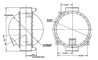
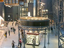
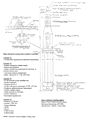
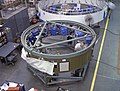
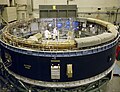
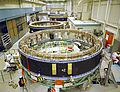
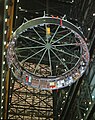
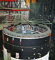
The ST-124-M3 inertial platform was a device for measuring acceleration and attitude of the Saturn V launch vehicle. It was carried by the Saturn V Instrument Unit, a 3-foot-high (0.91 m), 22-foot-diameter (6.7 m) section of the Saturn V that fit between the third stage (S-IVB) and the Apollo spacecraft. Its nomenclature means "stable table" (ST) for use in the Moon mission (M), and it has 3 gimbals.

<span class="mw-page-title-main">Saturn V dynamic test vehicle</span> Moon rocket test article in Huntsville, Alabama

The Saturn V dynamic test vehicle, designated SA-500D, is a prototype Saturn V rocket used by NASA to test the performance of the rocket when vibrated to simulate the shaking which subsequent rockets would experience during launch. It was the first full-scale Saturn V completed by the Marshall Space Flight Center (MSFC). Though SA-500D never flew, it was instrumental in the development of the Saturn V rocket which propelled the first men to the Moon as part of the Apollo program. Built under the direction of Dr. Wernher von Braun, it served as the test vehicle for all of the Saturn support facilities at MSFC.

<span class="mw-page-title-main">Saturn V</span> American super heavy-lift expendable rocket

The Saturn V is a retired American super heavy-lift launch vehicle developed by NASA under the Apollo program for human exploration of the Moon. The rocket was human-rated, had three stages, and was powered by liquid fuel. Flown from 1967 to 1973, it was used for nine crewed flights to the Moon, and to launch Skylab, the first American space station.

<span class="mw-page-title-main">ASC-15</span>

The ASC-15 was a digital computer developed by International Business Machines (IBM) for use on the Titan II intercontinental ballistic missile (ICBM). It was subsequently modified and used on the Titan III and Saturn I Block II launch vehicles.

References

Saturn

Apollo

Specific missions

Instrument unit

Instrument unit guidance

NASA computers

Notes

  1. "Instrument Unit Fact Sheet, Saturn V News Reference." Changed December 1968. Page 2.
  2. Roger E. Bilstein. Stages to Saturn. The NASA History Series, 1996. Chapter 8. From Checkout to Launch: The Quintessential Computer. IBM is also identified as the Instrument Unit builder on the nameplate of IU-514 at Udvar-Hazy Center. This nameplate is at the top left of location 7.
  3. "Saturn V Instrument Unit (IU) | NASM TAP". copilot.si.edu. Smithsonian Institution. Archived from the original on 2019-04-04. Retrieved 2017-09-22.
  4. "Saturn V instrument unit audio description". copilot.si.edu/. Smithsonian Institution. Retrieved 2017-09-22.
  5. ‘’Stages To Saturn’’ Chapter 8.
  6. The Apollo "A"/Saturn C-1 Launch Vehicle System
  7. Saturn I Summary PDF p. 36
  8. ‘’Saturn Illustrated Chronology’’, Appendix H. Moonport, Appendix A. Apollo Program Summary Report, Appendix A.
  9. "Saturn 1B History".
  10. "Space Launch Report . . . Saturn Vehicle History".
  11. "Space Launch Report . . . Saturn Vehicle History".
  12. "Astrionics System Handbook", 1 November 1968, MSFC No. IV-4-401-1. IBM No. 68-966-0002. Section 1.3. Saturn V Mission Profile.
  13. " Instrument Unit Fact Sheet. Saturn V News Reference." Changed December 1968. Pp. 5-6.
  14. "Saturn V Flight Manual SA-507." MSFC-MAN-507. Changed 5 October 1969. P. 2-1 (PDF page 15). Section II. Performance. Flight Sequence.
  15. "Astrionics System Handbook", 1 November 1968, MSFC No. IV-4-401-1. IBM No. 68-966-0002. P. 1.2-1 (PDF p. 15): The old and new coordinate systems are described. The new standard became effective for vehicles 204 and 502 (and subsequent).
  16. "Saturn I Summary." 15 February 1966.