3D reconstruction from multiple images

Last updated
A 3D selfie in 1:20 scale printed by Shapeways using gypsum-based printing, created by Madurodam miniature park from 2D pictures taken at its Fantasitron photo booth Madurodam Shapeways 3D selfie in 1 20 scale after a second spray of varnish FRD.jpg
A 3D selfie in 1:20 scale printed by Shapeways using gypsum-based printing, created by Madurodam miniature park from 2D pictures taken at its Fantasitron photo booth
3D models are generated from 2D pictures taken at the Fantasitron 3D photo booth at Madurodam. Fantasitron photo booth at Madurodam can scan up to two people at a time IMG 3797 FRD.jpg
3D models are generated from 2D pictures taken at the Fantasitron 3D photo booth at Madurodam.
Generating and reconstructing 3D shapes from single or multi-view depth maps or silhouettes Synthesizing 3D Shapes via Modeling Multi-View Depth Maps and Silhouettes With Deep Generative Networks.png
Generating and reconstructing 3D shapes from single or multi-view depth maps or silhouettes

3D reconstruction from multiple images is the creation of three-dimensional models from a set of images. It is the reverse process of obtaining 2D images from 3D scenes.

Contents

The essence of an image is a projection from a 3D scene onto a 2D plane, during which process the depth is lost. The 3D point corresponding to a specific image point is constrained to be on the line of sight. From a single image, it is impossible to determine which point on this line corresponds to the image point. If two images are available, then the position of a 3D point can be found as the intersection of the two projection rays. This process is referred to as triangulation. The key for this process is the relations between multiple views which convey the information that corresponding sets of points must contain some structure and that this structure is related to the poses and the calibration of the camera.

In recent decades, there is an important demand for 3D content for computer graphics, virtual reality and communication, triggering a change in emphasis for the requirements. Many existing systems for constructing 3D models are built around specialized hardware (e.g. stereo rigs) resulting in a high cost, which cannot satisfy the requirement of its new applications. This gap stimulates the use of digital imaging facilities (like a camera). An early method was proposed by Tomasi and Kanade. [2] They used an affine factorization approach to extract 3D from images sequences. However, the assumption of orthographic projection is a significant limitation of this system.

Processing

A visual hull can be reconstructed from multiple silhouettes of an object. SilhouetteCones.jpg
A visual hull can be reconstructed from multiple silhouettes of an object.

The task of converting multiple 2D images into 3D model consists of a series of processing steps:

Camera calibration consists of intrinsic and extrinsic parameters, without which at some level no arrangement of algorithms can work. The dotted line between Calibration and Depth determination represents that the camera calibration is usually required for determining depth.

Depth determination serves as the most challenging part in the whole process, as it calculates the 3D component missing from any given image – depth. The correspondence problem, finding matches between two images so the position of the matched elements can then be triangulated in 3D space is the key issue here.

Once you have the multiple depth maps you have to combine them to create a final mesh by calculating depth and projecting out of the camera – registration . Camera calibration will be used to identify where the many meshes created by depth maps can be combined to develop a larger one, providing more than one view for observation.

By the stage of Material Application you have a complete 3D mesh, which may be the final goal, but usually you will want to apply the color from the original photographs to the mesh. This can range from projecting the images onto the mesh randomly, through approaches of combining the textures for super resolution and finally to segmenting the mesh by material, such as specular and diffuse properties.

Mathematical description of reconstruction

Given a group of 3D points viewed by N cameras with matrices , define to be the homogeneous coordinates of the projection of the point onto the camera. The reconstruction problem can be changed to: given the group of pixel coordinates , find the corresponding set of camera matrices and the scene structure such that

(1)

Generally, without further restrictions, we will obtain a projective reconstruction. [4] [5] If and satisfy (1), and will satisfy (1) with any 4 × 4 nonsingular matrix T.

A projective reconstruction can be calculated by correspondence of points only without any a priori information.

Auto-calibration

In auto-calibration or self-calibration, camera motion and parameters are recovered first, using rigidity. Then structure can be readily calculated. Two methods implementing this idea are presented as follows:

Kruppa equations

With a minimum of three displacements, we can obtain the internal parameters of the camera using a system of polynomial equations due to Kruppa, [6] which are derived from a geometric interpretation of the rigidity constraint. [7] [8]

The matrix is unknown in the Kruppa equations, named Kruppa coefficients matrix. With K and by the method of Cholesky factorization one can obtain the intrinsic parameters easily:

Recently Hartley [9] proposed a simpler form. Let be written as , where

Then the Kruppa equations are rewritten (the derivation can be found in [9] )

Mendonça and Cipolla

This method is based on the use of rigidity constraint. Design a cost function, which considers the intrinsic parameters as arguments and the fundamental matrices as parameters. is defined as the fundamental matrix, and as intrinsic parameters matrices.

Stratification

Recently, new methods based on the concept of stratification have been proposed. [10] Starting from a projective structure, which can be calculated from correspondences only, upgrade this projective reconstruction to a Euclidean reconstruction, by making use of all the available constraints. With this idea the problem can be stratified into different sections: according to the amount of constraints available, it can be analyzed at a different level, projective, affine or Euclidean.

The stratification of 3D geometry

Usually, the world is perceived as a 3D Euclidean space. In some cases, it is not possible to use the full Euclidean structure of 3D space. The simplest being projective, then the affine geometry which forms the intermediate layers and finally Euclidean geometry. The concept of stratification is closely related to the series of transformations on geometric entities: in the projective stratum is a series of projective transformations (a homography), in the affine stratum is a series of affine transformations, and in Euclidean stratum is a series of Euclidean transformations.

Suppose that a fixed scene is captured by two or more perspective cameras and the correspondences between visible points in different images are already given. However, in practice, the matching is an essential and extremely challenging issue in computer vision. Here, we suppose that 3D points are observed by cameras with projection matrices Neither the positions of point nor the projection of camera are known. Only the projections of the point in the image are known.

Projective reconstruction

Simple counting indicates we have independent measurements and only unknowns, so the problem is supposed to be soluble with enough points and images. The equations in homogeneous coordinates can be represented:

(2)

So we can apply a nonsingular 4 × 4 transformation H to projections and world points . Hence, without further constraints, reconstruction is only an unknown projective deformation of the 3D world.

Affine reconstruction

See affine space for more detailed information about computing the location of the plane at infinity . The simplest way is to exploit prior knowledge, for example the information that lines in the scene are parallel or that a point is the one thirds between two others.

We can also use prior constraints on the camera motion. By analyzing different images of the same point can obtain a line in the direction of motion. The intersection of several lines is the point at infinity in the motion direction, and one constraint on the affine structure.

Euclidean reconstruction

By mapping the projective reconstruction to one that satisfies a group of redundant Euclidean constraints, we can find a projective transformation H in equation (2).The equations are highly nonlinear and a good initial guess for the structure is required. This can be obtained by assuming a linear projection - parallel projection, which also allows easy reconstruction by SVD decomposition. [2]

Algebraic vs geometric error

Inevitably, measured data (i.e., image or world point positions) is noisy and the noise comes from many sources. To reduce the effect of noise, we usually use more equations than necessary and solve with least squares.

For example, in a typical null-space problem formulation Ax = 0 (like the DLT algorithm), the square of the residual ||Ax|| is being minimized with the least squares method.

In general, if ||Ax|| can be considered as a distance between the geometrical entities (points, lines, planes, etc.), then what is being minimized is a geometric error, otherwise (when the error lacks a good geometrical interpretation) it is called an algebraic error.

Therefore, compared with algebraic error, we prefer to minimize a geometric error for the reasons listed:

  1. The quantity being minimized has a meaning.
  2. The solution is more stable.
  3. The solution is constant under Euclidean transforms.

All the linear algorithms (DLT and others) we have seen so far minimize an algebraic error. Actually, there is no justification in minimizing an algebraic error apart from the ease of implementation, as it results in a linear problem. The minimization of a geometric error is often a non-linear problem, that admit only iterative solutions and requires a starting point.

Usually, linear solution based on algebraic residuals serves as a starting point for a non-linear minimization of a geometric cost function, which provides the solution a final “polish”. [11]

Medical applications

The 2-D imaging has problems of anatomy overlapping with each other and do not disclose the abnormalities. The 3-D imaging can be used for both diagnostic and therapeutic purposes.

3-D models are used for planning the operation, morphometric studies and has more reliability in orthopedics. [12]

Projection of P on both cameras Epipolar Geometry1.svg
Projection of P on both cameras

Problem statement & Basics

To reconstruct 3-D images from 2-D images taken by a camera at multiple angles. Medical imaging techniques like CT scanning and MRI are expensive, and although CT scans are accurate, they can induce high radiation doses which is a risk for patients with certain diseases. Methods based on MRI are not accurate. Since we are exposed to powerful magnetic fields during an MRI scan, this method is not suitable for patients with ferromagnetic metallic implants. Both the methods can be done only when in lying position where the global structure of the bone changes. So, we discuss the following methods which can be performed while standing and require low radiation dose.

Though these techniques are 3-D imaging, the region of interest is restricted to a slice; data are acquired to form a time sequence.

Stereo Corresponding Point Based Technique

This method is simple and implemented by identifying the points manually in multi-view radiographs. The first step is to extract the corresponding points in two x-ray images. The second step is to reconstruct the image in three dimensions using algorithms like Discrete Linear Transform (DLT). [13] The reconstruction is only possible where there are Stereo Corresponding Points (SCPs). The quality of the results are dependent on the quantity of SCPs, the more SCPs, the better the results [14] but it is slow and inaccurate. The skill of the operator is a factor in the quality of the image. SCP based techniques are not suitable for bony structures without identifiable edges. Generally, SCP based techniques are used as part of a process involving other methods. [15]

Non-Stereo corresponding contour method (NCSS)

This method uses X-ray images for 3D Reconstruction and to develop 3D models with low dose radiations in weight bearing positions.

In NSCC algorithm, the preliminary step is calculation of an initial solution. Firstly anatomical regions from the generic object are defined. Secondly, manual 2D contours identification on the radiographs is performed. From each radiograph 2D contours are generated using the 3D initial solution object. 3D contours of the initial object surface are projected onto their associated radiograph. [15] The 2D association performed between these 2 set points is based on point-to-point distances and contours derivations developing a correspondence between the 2D contours and the 3D contours. Next step is optimization of the initial solution. Lastly deformation of the optimized solution is done by applying Kriging algorithm to the optimized solution. [16] Finally, by iterating the final step until the distance between two set points is superior to a given precision value the reconstructed object is obtained.

The advantage of this method is it can be used for bony structures with continuous shape and it also reduced human intervention but they are time-consuming.

Surface rendering technique

Surface rendering visualizes a 3D object as a set of surfaces called iso-surfaces. Each surface has points with the same intensity (called an iso-value). This technique is usually applied to high contrast data, and helps to illustrate separated structures; for instance, the skull can be created from slices of the head, or the blood vessel system from slices of the body. Two main methods are:

  • Contour based reconstruction: Iso-contours are attached to each other to form iso-surfaces. [17]
  • Voxel based reconstruction: Voxels of the same intensity value are used to form iso-surfaces. Popular algorithms are Marching Cubes, Marching Tetrahedrons and Dividing Cubes. [17]

Other methods use statistical shape models, parametrics, or hybrids of the two

See also

Related Research Articles

<span class="mw-page-title-main">Reflection (mathematics)</span> Mapping from a Euclidean space to itself

In mathematics, a reflection is a mapping from a Euclidean space to itself that is an isometry with a hyperplane as a set of fixed points; this set is called the axis or plane of reflection. The image of a figure by a reflection is its mirror image in the axis or plane of reflection. For example the mirror image of the small Latin letter p for a reflection with respect to a vertical axis would look like q. Its image by reflection in a horizontal axis would look like b. A reflection is an involution: when applied twice in succession, every point returns to its original location, and every geometrical object is restored to its original state.

<span class="mw-page-title-main">3D projection</span> Design technique

A 3D projection is a design technique used to display a three-dimensional (3D) object on a two-dimensional (2D) surface. These projections rely on visual perspective and aspect analysis to project a complex object for viewing capability on a simpler plane.

<span class="mw-page-title-main">Curve fitting</span> Process of constructing a curve that has the best fit to a series of data points

Curve fitting is the process of constructing a curve, or mathematical function, that has the best fit to a series of data points, possibly subject to constraints. Curve fitting can involve either interpolation, where an exact fit to the data is required, or smoothing, in which a "smooth" function is constructed that approximately fits the data. A related topic is regression analysis, which focuses more on questions of statistical inference such as how much uncertainty is present in a curve that is fitted to data observed with random errors. Fitted curves can be used as an aid for data visualization, to infer values of a function where no data are available, and to summarize the relationships among two or more variables. Extrapolation refers to the use of a fitted curve beyond the range of the observed data, and is subject to a degree of uncertainty since it may reflect the method used to construct the curve as much as it reflects the observed data.

In linear algebra, linear transformations can be represented by matrices. If is a linear transformation mapping to and is a column vector with entries, then

The scale-invariant feature transform (SIFT) is a computer vision algorithm to detect, describe, and match local features in images, invented by David Lowe in 1999. Applications include object recognition, robotic mapping and navigation, image stitching, 3D modeling, gesture recognition, video tracking, individual identification of wildlife and match moving.

In visual effects, match moving is a technique that allows the insertion of 2D elements, other live action elements or CG computer graphics into live-action footage with correct position, scale, orientation, and motion relative to the photographed objects in the shot. It also allows for the removal of live action elements from the live action shot. The term is used loosely to describe several different methods of extracting camera motion information from a motion picture. Sometimes referred to as motion tracking or camera solving, match moving is related to rotoscoping and photogrammetry. Match moving is sometimes confused with motion capture, which records the motion of objects, often human actors, rather than the camera. Typically, motion capture requires special cameras and sensors and a controlled environment. Match moving is also distinct from motion control photography, which uses mechanical hardware to execute multiple identical camera moves. Match moving, by contrast, is typically a software-based technology, applied after the fact to normal footage recorded in uncontrolled environments with an ordinary camera.

<span class="mw-page-title-main">Geometry processing</span>

Geometry processing is an area of research that uses concepts from applied mathematics, computer science and engineering to design efficient algorithms for the acquisition, reconstruction, analysis, manipulation, simulation and transmission of complex 3D models. As the name implies, many of the concepts, data structures, and algorithms are directly analogous to signal processing and image processing. For example, where image smoothing might convolve an intensity signal with a blur kernel formed using the Laplace operator, geometric smoothing might be achieved by convolving a surface geometry with a blur kernel formed using the Laplace-Beltrami operator.

<span class="mw-page-title-main">Image stitching</span> Combining multiple photographic images with overlapping fields of view

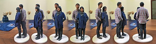
Image stitching or photo stitching is the process of combining multiple photographic images with overlapping fields of view to produce a segmented panorama or high-resolution image. Commonly performed through the use of computer software, most approaches to image stitching require nearly exact overlaps between images and identical exposures to produce seamless results, although some stitching algorithms actually benefit from differently exposed images by doing high-dynamic-range imaging in regions of overlap. Some digital cameras can stitch their photos internally.

In the fields of computing and computer vision, pose represents the position and orientation of an object, usually in three dimensions. Poses are often stored internally as transformation matrices. The term “pose” is largely synonymous with the term “transform”, but a transform may often include scale, whereas pose does not.

Camera resectioning is the process of estimating the parameters of a pinhole camera model approximating the camera that produced a given photograph or video; it determines which incoming light ray is associated with each pixel on the resulting image. Basically, the process determines the pose of the pinhole camera.

<span class="mw-page-title-main">Image rectification</span>

Image rectification is a transformation process used to project images onto a common image plane. This process has several degrees of freedom and there are many strategies for transforming images to the common plane. Image rectification is used in computer stereo vision to simplify the problem of finding matching points between images, and in geographic information systems to merge images taken from multiple perspectives into a common map coordinate system.

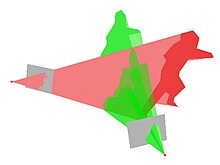
The difference-map algorithm is a search algorithm for general constraint satisfaction problems. It is a meta-algorithm in the sense that it is built from more basic algorithms that perform projections onto constraint sets. From a mathematical perspective, the difference-map algorithm is a dynamical system based on a mapping of Euclidean space. Solutions are encoded as fixed points of the mapping.

Compressed sensing is a signal processing technique for efficiently acquiring and reconstructing a signal, by finding solutions to underdetermined linear systems. This is based on the principle that, through optimization, the sparsity of a signal can be exploited to recover it from far fewer samples than required by the Nyquist–Shannon sampling theorem. There are two conditions under which recovery is possible. The first one is sparsity, which requires the signal to be sparse in some domain. The second one is incoherence, which is applied through the isometric property, which is sufficient for sparse signals. Compressed sensing has applications in, for example, MRI where the incoherence condition is typically satisfied.

In computer vision, triangulation refers to the process of determining a point in 3D space given its projections onto two, or more, images. In order to solve this problem it is necessary to know the parameters of the camera projection function from 3D to 2D for the cameras involved, in the simplest case represented by the camera matrices. Triangulation is sometimes also referred to as reconstruction or intersection.

<span class="mw-page-title-main">Bundle adjustment</span>

In photogrammetry and computer stereo vision, bundle adjustment is simultaneous refining of the 3D coordinates describing the scene geometry, the parameters of the relative motion, and the optical characteristics of the camera(s) employed to acquire the images, given a set of images depicting a number of 3D points from different viewpoints. Its name refers to the geometrical bundles of light rays originating from each 3D feature and converging on each camera's optical center, which are adjusted optimally according to an optimality criterion involving the corresponding image projections of all points.

In computer vision, 3D object recognition involves recognizing and determining 3D information, such as the pose, volume, or shape, of user-chosen 3D objects in a photograph or range scan. Typically, an example of the object to be recognized is presented to a vision system in a controlled environment, and then for an arbitrary input such as a video stream, the system locates the previously presented object. This can be done either off-line, or in real-time. The algorithms for solving this problem are specialized for locating a single pre-identified object, and can be contrasted with algorithms which operate on general classes of objects, such as face recognition systems or 3D generic object recognition. Due to the low cost and ease of acquiring photographs, a significant amount of research has been devoted to 3D object recognition in photographs.

<span class="mw-page-title-main">3D reconstruction</span> Process of capturing the shape and appearance of real objects

In computer vision and computer graphics, 3D reconstruction is the process of capturing the shape and appearance of real objects. This process can be accomplished either by active or passive methods. If the model is allowed to change its shape in time, this is referred to as non-rigid or spatio-temporal reconstruction.

Camera auto-calibration is the process of determining internal camera parameters directly from multiple uncalibrated images of unstructured scenes. In contrast to classic camera calibration, auto-calibration does not require any special calibration objects in the scene. In the visual effects industry, camera auto-calibration is often part of the "Match Moving" process where a synthetic camera trajectory and intrinsic projection model are solved to reproject synthetic content into video.

<span class="mw-page-title-main">Point-set registration</span> Process of finding a spatial transformation that aligns two point clouds

In computer vision, pattern recognition, and robotics, point-set registration, also known as point-cloud registration or scan matching, is the process of finding a spatial transformation that aligns two point clouds. The purpose of finding such a transformation includes merging multiple data sets into a globally consistent model, and mapping a new measurement to a known data set to identify features or to estimate its pose. Raw 3D point cloud data are typically obtained from Lidars and RGB-D cameras. 3D point clouds can also be generated from computer vision algorithms such as triangulation, bundle adjustment, and more recently, monocular image depth estimation using deep learning. For 2D point set registration used in image processing and feature-based image registration, a point set may be 2D pixel coordinates obtained by feature extraction from an image, for example corner detection. Point cloud registration has extensive applications in autonomous driving, motion estimation and 3D reconstruction, object detection and pose estimation, robotic manipulation, simultaneous localization and mapping (SLAM), panorama stitching, virtual and augmented reality, and medical imaging.

Perspective-n-Point is the problem of estimating the pose of a calibrated camera given a set of n 3D points in the world and their corresponding 2D projections in the image. The camera pose consists of 6 degrees-of-freedom (DOF) which are made up of the rotation and 3D translation of the camera with respect to the world. This problem originates from camera calibration and has many applications in computer vision and other areas, including 3D pose estimation, robotics and augmented reality. A commonly used solution to the problem exists for n = 3 called P3P, and many solutions are available for the general case of n ≥ 3. A solution for n = 2 exists if feature orientations are available at the two points. Implementations of these solutions are also available in open source software.

References

  1. "Soltani, A. A., Huang, H., Wu, J., Kulkarni, T. D., & Tenenbaum, J. B. Synthesizing 3D Shapes via Modeling Multi-View Depth Maps and Silhouettes With Deep Generative Networks. In Proceedings of the IEEE Conference on Computer Vision and Pattern Recognition (pp. 1511-1519)". GitHub . 6 March 2020.
  2. 1 2 C. Tomasi and T. Kanade, “Shape and motion from image streams under orthography: A factorization approach”, International Journal of Computer Vision, 9(2):137-154, 1992.
  3. A. Laurentini (February 1994). "The visual hull concept for silhouette-based image understanding". IEEE Transactions on Pattern Analysis and Machine Intelligence. 16 (2): 150–162. doi:10.1109/34.273735.
  4. R. Mohr and E. Arbogast. It can be done without camera calibration. Pattern Recognition Letters, 12:39-43, 1991.
  5. O. Faugeras. What can be seen in three dimensions with an uncalibrated stereo rig? In Proceedings of the European Conference on Computer Vision, pages 563-578, Santa Margherita L., 1992.
  6. E. Kruppa. Zur Ermittlung eines Objektes aus zwei Perspektiven mit innerer Orientierung. Sitz.-Ber.Akad.Wiss., Wien, math. naturw. Kl., Abt. IIa., 122:1939-1948, 1913.
  7. S. J. Maybank and O. Faugeras. A theory of self-calibration of a moving camera. International Journal of Computer Vision, 8(2):123-151, 1992.
  8. O. Faugeras and S. Maybank. Motion from point matches: multiplicity of solutions. International Journal of Computer Vision, 4(3):225-246, June 1990.
  9. 1 2 R. I. Hartley. Kruppa's equations derived from the fundamental matrix Archived 2018-06-22 at the Wayback Machine . IEEE Transactions on Pattern Analysis and Machine Intelligence, 19(2):133-135, February 1997.
  10. Pollefeys, Marc. Self-calibration and metric 3D reconstruction from uncalibrated image sequences. Diss. PhD thesis, ESAT-PSI, KU Leuven, 1999.
  11. R. Hartley and A. Zisserman. Multiple view geometry in computer vision. Cambridge University Press, 2nd edition, 2003.
  12. "Medical Visualization: What is it and what's it for?". GarageFarm. 2018-02-18. Retrieved 2018-02-18.
  13. "Pearcy MJ. 1985. Stereo radiography of lumbar spine motion. Acta Orthop Scand Suppl".
  14. "Aubin CE, Dansereau J, Parent F, Labelle H, de Guise JA. 1997. Morphometric evaluations of personalised 3D reconstructions and geometric models of the human spine". Med Biol Eng Comput.
  15. 1 2 "S.Hosseinian, H.Arefi, 3D Reconstruction from multiview medical X-ray images- Review and evaluation of existing methods" (PDF).
  16. Laporte, S; Skalli, W; de Guise, JA; Lavaste, F; Mitton, D (2003). "A biplanar reconstruction method based on 2D and 3D contours: application to distal femur". Comput Methods Biomech Biomed Engin. 6 (1): 1–6. doi:10.1080/1025584031000065956. PMID   12623432. S2CID   3206752.
  17. 1 2 G.Scott Owen, HyperVis. ACM SIGGRAPH Education Committee, the National Science Foundation (DUE-9752398), and the Hypermedia and Visualization Laboratory, Georgia State University.

Further reading